US4456883A - Method and apparatus for indicating an operating characteristic of an internal combustion engine - Google Patents
Method and apparatus for indicating an operating characteristic of an internal combustion engineDownload PDFInfo
- Publication number
- US4456883A US4456883AUS06/432,501US43250182AUS4456883AUS 4456883 AUS4456883 AUS 4456883AUS 43250182 AUS43250182 AUS 43250182AUS 4456883 AUS4456883 AUS 4456883A
- Authority
- US
- United States
- Prior art keywords
- exhaust gas
- engine
- electrode
- gas stream
- packets
- Prior art date
- Legal status (The legal status is an assumption and is not a legal conclusion. Google has not performed a legal analysis and makes no representation as to the accuracy of the status listed.)
- Expired - Lifetime
Links
- 238000002485combustion reactionMethods0.000titleclaimsabstractdescription50
- 238000000034methodMethods0.000titleclaimsabstractdescription21
- 239000002245particleSubstances0.000claimsabstractdescription81
- 239000012212insulatorSubstances0.000claimsabstractdescription30
- 230000000737periodic effectEffects0.000claimsabstractdescription14
- 239000004071sootSubstances0.000claimsabstractdescription10
- 230000008021depositionEffects0.000claimsabstractdescription3
- 239000000446fuelSubstances0.000claimsdescription11
- 238000012544monitoring processMethods0.000claimsdescription8
- 238000002955isolationMethods0.000claimsdescription4
- 230000000007visual effectEffects0.000claimsdescription4
- 230000008859changeEffects0.000claimsdescription3
- 230000003094perturbing effectEffects0.000claimsdescription3
- 230000004323axial lengthEffects0.000claims1
- 238000010835comparative analysisMethods0.000claims1
- 239000000523sampleSubstances0.000abstractdescription42
- 230000010349pulsationEffects0.000abstractdescription4
- 238000011156evaluationMethods0.000abstractdescription2
- 239000007789gasSubstances0.000description61
- 239000000779smokeSubstances0.000description11
- 238000005259measurementMethods0.000description6
- 238000009825accumulationMethods0.000description4
- 230000003287optical effectEffects0.000description4
- 230000006698inductionEffects0.000description3
- 230000008569processEffects0.000description3
- 238000000926separation methodMethods0.000description3
- 238000012360testing methodMethods0.000description3
- 230000002159abnormal effectEffects0.000description2
- 238000013459approachMethods0.000description2
- 239000000919ceramicSubstances0.000description2
- 230000006835compressionEffects0.000description2
- 238000007906compressionMethods0.000description2
- 230000007423decreaseEffects0.000description2
- 238000001514detection methodMethods0.000description2
- 238000009826distributionMethods0.000description2
- 238000010304firingMethods0.000description2
- 230000008439repair processEffects0.000description2
- 230000004044responseEffects0.000description2
- 238000012935AveragingMethods0.000description1
- OKTJSMMVPCPJKN-UHFFFAOYSA-NCarbonChemical compound[C]OKTJSMMVPCPJKN-UHFFFAOYSA-N0.000description1
- 230000002411adverseEffects0.000description1
- 239000000443aerosolSubstances0.000description1
- 230000015572biosynthetic processEffects0.000description1
- 229910052799carbonInorganic materials0.000description1
- 238000006243chemical reactionMethods0.000description1
- 238000004140cleaningMethods0.000description1
- 230000002950deficientEffects0.000description1
- 230000001419dependent effectEffects0.000description1
- 238000010790dilutionMethods0.000description1
- 239000012895dilutionSubstances0.000description1
- 238000006073displacement reactionMethods0.000description1
- 230000000694effectsEffects0.000description1
- 238000010292electrical insulationMethods0.000description1
- 230000003628erosive effectEffects0.000description1
- 230000007274generation of a signal involved in cell-cell signalingEffects0.000description1
- 238000004519manufacturing processMethods0.000description1
- 239000002184metalSubstances0.000description1
- 239000000203mixtureSubstances0.000description1
- 230000037230mobilityEffects0.000description1
- 230000035945sensitivityEffects0.000description1
- 239000007787solidSubstances0.000description1
- 239000013589supplementSubstances0.000description1
- 230000001960triggered effectEffects0.000description1
- 238000011144upstream manufacturingMethods0.000description1
Images

Classifications
- F—MECHANICAL ENGINEERING; LIGHTING; HEATING; WEAPONS; BLASTING
- F02—COMBUSTION ENGINES; HOT-GAS OR COMBUSTION-PRODUCT ENGINE PLANTS
- F02D—CONTROLLING COMBUSTION ENGINES
- F02D41/00—Electrical control of supply of combustible mixture or its constituents
- F02D41/02—Circuit arrangements for generating control signals
- F02D41/14—Introducing closed-loop corrections
- F02D41/1438—Introducing closed-loop corrections using means for determining characteristics of the combustion gases; Sensors therefor
- F02D41/1444—Introducing closed-loop corrections using means for determining characteristics of the combustion gases; Sensors therefor characterised by the characteristics of the combustion gases
- F02D41/1466—Introducing closed-loop corrections using means for determining characteristics of the combustion gases; Sensors therefor characterised by the characteristics of the combustion gases the characteristics being a soot concentration or content
- F—MECHANICAL ENGINEERING; LIGHTING; HEATING; WEAPONS; BLASTING
- F02—COMBUSTION ENGINES; HOT-GAS OR COMBUSTION-PRODUCT ENGINE PLANTS
- F02D—CONTROLLING COMBUSTION ENGINES
- F02D41/00—Electrical control of supply of combustible mixture or its constituents
- F02D41/22—Safety or indicating devices for abnormal conditions
- G—PHYSICS
- G01—MEASURING; TESTING
- G01M—TESTING STATIC OR DYNAMIC BALANCE OF MACHINES OR STRUCTURES; TESTING OF STRUCTURES OR APPARATUS, NOT OTHERWISE PROVIDED FOR
- G01M15/00—Testing of engines
- G01M15/04—Testing internal-combustion engines
- G—PHYSICS
- G01—MEASURING; TESTING
- G01N—INVESTIGATING OR ANALYSING MATERIALS BY DETERMINING THEIR CHEMICAL OR PHYSICAL PROPERTIES
- G01N15/00—Investigating characteristics of particles; Investigating permeability, pore-volume or surface-area of porous materials
- G01N15/06—Investigating concentration of particle suspensions
- G01N15/0656—Investigating concentration of particle suspensions using electric, e.g. electrostatic methods or magnetic methods
- G—PHYSICS
- G01—MEASURING; TESTING
- G01N—INVESTIGATING OR ANALYSING MATERIALS BY DETERMINING THEIR CHEMICAL OR PHYSICAL PROPERTIES
- G01N27/00—Investigating or analysing materials by the use of electric, electrochemical, or magnetic means
- G01N27/62—Investigating or analysing materials by the use of electric, electrochemical, or magnetic means by investigating the ionisation of gases, e.g. aerosols; by investigating electric discharges, e.g. emission of cathode
- F—MECHANICAL ENGINEERING; LIGHTING; HEATING; WEAPONS; BLASTING
- F02—COMBUSTION ENGINES; HOT-GAS OR COMBUSTION-PRODUCT ENGINE PLANTS
- F02B—INTERNAL-COMBUSTION PISTON ENGINES; COMBUSTION ENGINES IN GENERAL
- F02B3/00—Engines characterised by air compression and subsequent fuel addition
- F02B3/06—Engines characterised by air compression and subsequent fuel addition with compression ignition
- F—MECHANICAL ENGINEERING; LIGHTING; HEATING; WEAPONS; BLASTING
- F02—COMBUSTION ENGINES; HOT-GAS OR COMBUSTION-PRODUCT ENGINE PLANTS
- F02D—CONTROLLING COMBUSTION ENGINES
- F02D41/00—Electrical control of supply of combustible mixture or its constituents
- F02D41/008—Controlling each cylinder individually
Definitions
- This inventionrelates to the technique and apparatus for indicating an operating characteristic of an internal combustion engine and more specifically to the method and apparatus for sensing the particulate in the exhaust gas stream issuing in a periodic manner from an internal combustion engine and indicating an operating condition of the engine from the sensed particulate.
- the present industry standards for particulate emission measurementsare opacity meters, which employ optical techniques and gas filter patch samples.
- the opacity meterwhich provides greater measurement flexibility and continuous measurement capability operates on optical principles which require the provision of a source of light and means for sensing the level of light transmitted through and/or reflected by particles contained in the exhaust gas stream.
- Opacity metersrequire a relatively stable mounting arrangement and frequent cleaning and are not particularly well suited for on-vehicle applications. Moreover, the relatively high cost of opacity meters minimizes their appeal in a large volume market. Lastly, because of the optical characteristics typical of these meters, particle emissions one micron in size and larger have a greater sensitivity to detection than particles below the one micron level. Accordingly, most optical detectors are referred to as smoke meters rather than particulate emissions detectors because of this size discrimination effect which does not present a representative picture of the total exhaust gas particulate emissions.
- Instrumentshave existed for measuring the concentration of particles, i.e. aerosols, in a flowing gas stream utilizing electrostatic techniques. However, these instruments typically establish a high voltage corona in the particle flow path for placing a charge on the flowing particles. Examples of such instruments are illustrated and disclosed in U.S. Pat. No. 3,526,828 issued Sept. 1, 1970 to K. T. Whitby for Method and Apparatus for Measuring Particle Concentration and in U.S. Pat. No. 3,114,877 issued Dec. 17, 1963 to S. B. Dunham for Particle Detector Having Improved Unipolar Charging Structure. In U.S. Pat. No. 3,359,796 issued Dec. 26, 1967 to R. C.
- an instrumentwhich measures the mass flow of charged solid particles entrained in a flowing gas stream, which particle charges are acquired by frictional contact with the wall of the conduit. Impact of the charged particles with a sensor element creates a small electrical current which is used as a measure of the particle mass flow. Operation of this device is limited to situations where frictional charging is the principal charging process and where flow velocities are low enough for impact charge collection to overcome gas dynamics. Thus, no consideration is given to using that device for measuring the emission level of particulates in the exhaust from an internal combustion engine.
- a smoke measuring device for the exhaust gases from internal combustion enginesis described in U.S. Pat. No. 3,744,461 issued July 10, 1973 to J. D. Davis for Method and Apparatus for Reducing Exhaust Smoke in Internal Combustion Engines. That smoke measuring device utilizes the principle that carbon particles in the exhaust gas stream issuing from an internal combustion engine are electrically charged. An electrode is placed in the exhaust gas stream, the charges are collected at the electrode by impaction, and electrical circuitry provides an output signal corresponding to the potential developed between the electrode and the exhaust duct, which signal may, in highly selective cases such as low flow velocity, be indicative of a smoke density level and may be used to control the quantity of fuel delivered to the engine.
- the smoke measuring device of the aforementioned Davis patentwhile providing some measure of the particulate level in an engine exhaust gas stream, also exhibits certain limitations.
- the electrodeBy relying on charge collection by impaction, the electrode must have a relatively large surface area in and/or adjacent to the gas stream and requires a significant electrical potential to overcome gas dynamic flow stream forces. Further, the impaction process can significantly shorten the life of the electrode by erosion. Additionally, because of the large extent of the electrode in the direction of gas flow, the resulting signal is generally representative of an average of the discrete exhaust outputs of several cylinders.
- a principal object of the present inventionto provide an improved apparatus for indicating an operating characteristic of a periodically combusting internal combustion engine by sensing the particulate emissions in the exhaust gas stream issuing from the engine and deriving the indication therefrom.
- a technique and apparatus for indicating an operating characteristic of a periodically combusting internal combustion enginewhich engine has one or more combustion chambers and an exhaust gas stream issuing in a periodic manner through ducting from the combustion chambers.
- the exhaust gas streamcontains electrically charged particles of the same polarity at a monitoring location downstream of the engine combustion chambers, and the engine's periodic discharge of exhaust gas from respective cylinders causes the charged particles to be grouped in packets.
- An electrically conductive passive electrodepreferably of annular configuration, is disposed in proximity with the exhaust gas stream at the monitoring location to electrostatically sense, principally by means of an induced image charge, the passage of the respective packets of charged particles.
- the electrodeis electrically isolated from the exhaust duct and is preferably configured and/or positioned to minimize any blockage of the flow of exhaust gas.
- Signal developing circuitryis connected to the sensing electrode for providing an electrical signal in response to the sensed passage of the particle packets. That signal contains a series of distinct pulsating components corresponding in time with the passage of the respective said particle packets and corresponding quantitatively with the charge-quantity of the respective particle packets.
- An indicating devicereceives these pulsating signals as its input and provides therefrom an indication of an operating characteristic of the engine.
- the sensing electrodeis an electrically conductive closed annulus or loop positioned in proximate coaxial relation with the exhaust gas stream and which preferably has an axial extent which is short relative to spacial dimension of successive particle packets.
- the electrodemay be incorporated in the exhaust gas duct or pipe, or it may be located a short distance beyond the downstream end thereof.
- the diameter of the annular electrodeis sufficiently large to enable a substantial portion or all of the exhaust gas stream to pass therethrough and may typically approach or exceed the diameter of the exhaust gas duct.
- the sensing electrodeeither is in, or is in close proximity with, the exhaust gas stream, it may be desirable to provide a guard ring for the conduction of leakage currents and/or a shadow shield to minimize the accumulation of soot on an insulating surface which supports the electrode.
- Signal developing circuitryis connected to the electrode such that a pulsating signal is developed thereby in response to the passage of respective charged particle packets through or otherwise past the sensing electrode.
- the resulting pulsating signalcorresponds in time with the passage of the respective charged particle packets and corresponds quantitatively with the charged particles in a respective packet. Due to considerations of Gauss' Law, the annular probe configuration provides equal weighting of each particle passing through the annulus independent of radial charge density distribution.
- a device responsive to at least the pulsating components of the developed signalprovides therefrom an indication of an operating characteristic of the engine.
- the devicemay respond to the root mean square of the pulsating signal to provide a quantitative indication of the level of particulate in the exhaust gas stream.
- the devicemay comprise a cathode ray tube or the like for displaying the successive pulsations of the signal waveform to afford evaluation of the performance of the respective individual cylinders and/or fuel injectors.
- correlation of a particular displayed signal with operation of a specific injectormay be accomplished by perturbing the operation of the particular injector and noting such change in the display of a particular signal in the sequence of signals corresponding to successive injectors.
- Such correlation of a particular displayed signal with a particular injectormight also be calculated automatically as a function of system geometry and present operating conditions.
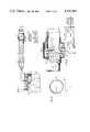
- FIG. 1is a diagrammatic view of an internal combustion engine having the electrostatic induction particulate sensor installed in the exhaust stream thereof and providing a pulsating signal to circuitry for indicating an operating characteristic of the engine;
- FIG. 2is a view of a preferred form of the electrostatic induction particulate-sensing probe viewed in the direction of exhaust gas flow;
- FIG. 3is a view of the probe of FIG. 2 perpendicular to the gas flow, including a mounting arrangement and illustrating the signal developing and utilizing circuitry in greater detail;
- FIG. 4is another mounting arrangement for a probe in accordance with the invention.
- FIG. 5is a further mounting arrangement for a probe in accordance with the invention.
- FIG. 6is a display of the sensed signal for relatively low-level particulate packets in the exhaust
- FIG. 7is a display of the sensed signal for relatively higher level particulate packets in the exhaust.
- FIG. 8is a display of the sensed signal for differing particulate levels in successive particulate packets from respective successive combustion chambers.
- FIG. 1there is depicted within one of the combustion chambers 10 of a multi-cylinder internal combustion engine, such as compression ignition engine 12, the ionization which results from the combustion process.
- This phenomenonin which the gas in the immediate combustion region becomes electrically conducting, is the well known principle upon which flame ionization and combustion detectors are based.
- various particulates 16are produced as a result of incomplete combustion. These particulates may vary in size and composition, and encompass a wide distribution, including many less than one micron in size. Since these particles 16 are produced within the individual cylinders of the engine, they provide sites upon which free charges resulting from the combustion process can attach. As is usual with attachment or clustering reactions taking place at atmospheric pressures or above, charge selection occurs, i.e. only positive or only negative charge species ultimately reside on the finely divided particles 16.
- the particles 16are shown to have acquired a positive charge as they begin movement away from the combustion chamber through the exhaust. Subsequent to the charge attachment process which takes place in combustion chamber 10, charge separation results as a consequence of the particles 16 being dominated by gas path flow forces, whereas the unattached charges, i.e. negative charges in FIG. 1, which have significantly greater mobilities because of their much smaller masses, are dominated by electrostatic forces. Accordingly, a rapid loss of these lighter (negative) particles to the walls of the cylinder and associated manifold results.
- the degree to which this charge separation occursis a function of the concentration of the particles 16 produced in each individual cylinder as a result of the incomplete combustion taking place. Specifically, the greater the formation of particles, the greater will be the attachment of one charge thereto and the separation therefrom of the other charge. Accordingly, determination of the quantity of charge provides a direct measure of the level of particulate in the engine exhaust gas stream.
- the detection of the charged particles 16' in the exhaust duct, or pipe, 20 of engine 12is accomplished by use of an electrically passive electrostatic induction probe or electrode 30 mounted downstream of the combustion chambers 10 in operative proximity with the exhaust gas stream.
- the term "electrically passive” as used hereinmeans the probe does not operate on an impaction or charge collection principle, and thus requires little or no biasing potential for signal generation, although some bias may be used in conjunction with a guard ring as described hereinafter.
- the probe 30might be mounted in an extension conduit associated with a test stand for connection with the exhaust pipe 20 of engine 12 to test or diagnose the engine. In another application, the probe 30 may be mounted directly in the exhaust system of an engine for on-vehicle use.
- An insulator 32provides electrical isolation from pipe 20.
- the key to providing a truly representative measure of the passage of particles 16' in the exhaustresides in the fact that relatively little or none of the actual charge on the particles is collected by the probe. Rather, the passage of substantially all of the charged particles is detected because an image charge of opposite sign is induced in the conducting probe electrode 30 as a charged particle approaches the vicinity of the probe surface. This results in a real electrical current flow through signal developing circuitry 33 connected to probe electrode 30, as will be hereinafter described.
- the induced image charge phenomenonas the charged particle recedes in the flow away from electrode 30, the magnitude of the induced charge on that electrode surface decreases, resulting in a current flow in the opposite direction.
- a time-resolved measurement or analysis of the signal, and specifically the AC-like pulsating signal induced in probe 30 by the passage of the exhaust gas puffs from the individual cylinders of the engineprovides this information directly.
- the charge induced in electrode 30, and thus current in the signal circuitryis a function of the number or quantity of charged particles 16 passing the electrode in the exhaust gas stream at the particular moment.
- An increase in particle concentration during respective exhaust gas puffsis manifested by an increase in the magnitude of the charge induced in electrode 30 and thus an increase in the voltage or current signal developed therefrom.
- Probe 30comprises an annular electrode formed of electrically conducting wire and oriented such that its axis is parallel to, and preferably substantially coaxial with, the axis or centerline of the exhaust gas flow in the tubular pipe 20. It will be understood that the conductive probe 30 may have an insulating covering without impeding its performance in the present invention.
- the electrode 30is shown mounted in and supported by ceramic insulator structure 32 which is in turn suitably mounted and sealed in an annular collar 60 which sealingly connects adjacent ends of pipe 20 at a break formed therein at a monitoring location.
- the length, l, of the electrode 30 axially of the gas flowis limited in order to obtain good signal resolution between successive packets of charged particles. It will be appreciated that as the number of combustion events per unit of time increases, the interval or length between successive particle packets decreases. Therefore, the length, l, of electrode 30 should be sufficiently short that at any instant it is sensing or responding to the charged particles of substantially only one packet, or preferably only an incremental portion thereof.
- the interval or spacing between charged particle maxima in successive packetswill, for a representative system, largely be a function of the number of engine cylinders, the engine's operating displacement, the speed of the engine and the geometry of the exhaust ducting system.
- an electrode length, l, of about 3-4 mmhas given good results.
- the length, l, of the electrode 30should generally be less than about 10-15 mm, which is much less than the typical diameter D of exhaust duct 20 thereat, i.e. 50 mm.
- the electrode 30is preferably affected by substantially all of the charged particles in a packet, rather than by a relative few nearest the electrode.
- a preferred electrode diameter, dis one which is sufficiently large to allow substantially all of the exhaust gas stream in duct 20 to pass therethrough.
- the electrode diameter, dpreferably is near or exceeds the duct diameter.
- the diameter, d, of electrode 30somewhat exceeds duct diameter, D, so that the entire gas stream flows therethrough and no flow blockage occurs.
- the radial thickness of an electrode 30is only about 1-4 mm to minimize its surface area transverse to the flowing gas so as to minimize any flow blockage, particularly if it is positioned in the gas stream.
- FIGS. 4 and 5there are illustrated alternative mounting arrangements for the electrostatic probe.
- the electrode 30'is also of annular form and insulated from pipe 20 by an insulator 32' which is sealingly installed directly in an opening in the wall of pipe 20.
- the diameter, d, of probe 30'is near, but slightly less than, the diameter, D, of pipe 20 so as to be in spaced (and thus insulated) relation with the pipe.
- substantially all of the exhaust gas stream and entrained particulatespass through this probe and provide a signal having the requisite properties, although this configuration does possess the limitations of increased restriction of the flow path and exposure to soot deposition.
- the electrode 30" of FIG. 5may also be annular, and is mounted in an insulator 32" which is supported by a bracket 70 mounted near the end of exhaust pipe 20.
- the electrode 30"may be located axially at or just beyond the end of pipe 20 such that the insulator 32" need not be mounted with a gas-tight seal.
- the insulator 32"may be positioned upstream of the end of pipe 20, to minimize or eliminate soot accumulation thereon.
- the probe electrodemight be embedded in an annular insulator, which insulator might be inserted into the exhaust duct or form an extension thereto. However, in such instance care must be taken to avoid build-up of soot or other conductive deposits on the insulator.
- a high degree of electrical isolation between probe 30 and the conductive portions of the duct 20must be maintained. If the insulator 32 is positioned such that it is exposed to the exhaust gas stream, the potential for soot accumulation on it exists, which may in turn give rise to leakage currents, particularly when damp. To minimize soot accumulation, one, or possibly two shadow shields 80 a and 80 b in FIG. 3 or 80' a and 80' b in FIG. 4, may be arranged to shadow the surface of the insulator from the direct gas flow.
- the insulator 32 in FIG. 3 and the insulator 32' in FIG. 4include guard rings 36, 36' respectively.
- Insulator 32is comprised of an inner cylindrical insulator 32a and a radially outer cylindrical insulator 32b concentric with insulator 32a.
- the base of annular electrode 30is fixedly mounted, as by a friction fit or bonding, into inner insulator 32a.
- the insulator 32also includes a conductive metal guard ring 36 intermediate and affixed to the inner and outer insulators 32a, 32b respectively.
- Guard ring 36is cylindrical and is concentric with insulators 32a, 32b and the portion of probe 30 extending therethrough.
- the guard ring 36is operated at substantially the same potential as the probe electrode 30, thus forming a region within and across the surface of the ceramic which is at substantially the same potential as the electrode 30. Accordingly, no leakage current can flow across this region. Leakage currents from the surrounding structure of engine 12 and exhaust duct 20 can pass over the outer insulator 32b, via the soot, to the guard ring 36. From the guard ring 36, these leakage currents are shunted to ground and therefore do not arrive at the probe electrode 30. Further, since the electrode 30 and the guard ring 36 are maintained at substantially the same potential, no leakage of currents occurs between the guard and the electrode.
- Signal developing circuitry 33is connected in the circuit of probe 30 between the probe and the ground reference potential.
- Signal developing circuitry 33includes a current-to-voltage converter 48 and a gain circuit 50. Assuming a 1 megohm resistor 51 across converter 48, a 1 microampere input provides a 1 volt output.
- Gain circuit 50may typically have a gain factor of fifty.
- the indicator 53consists of a root mean square (rms) volt meter 54 which is connected to the output of signal developing circuitry 33 to receive the signal voltage as its input.
- rmsroot mean square
- the output of the rms meter 54may be a visual indication of the root mean square value of the signal occasioned by the passage of successive charged particle packets through the exhaust duct 20. This indication may be calibrated and expressed in terms of the percentage of particulate in the exhaust gas stream or it may be referenced to opacity measurements and expressed as a change in opacity in the gas stream. Alternatively or additionally, with the appropriate time constants applied to the signal-averaging circuitry a substantially DC electrical signal indicative of the average value of particulate in the exhaust gas stream may be provided. Those time constants may be provided as function of engine combustion frequency. Such an indicating signal may additionally or alternatively be used for various control purposes.
- the indicating device 53might alternatively comprise a cathode ray tube (CRT) or similar display device for displaying the output signal from circuitry 33 in a time-resolved manner.
- the signal provided by circuitry 33may comprise the vertical, or Y, input to an X-Y display in which time is measured along the X axis.
- the pulsations appearing across resistor 50 as a result of the passage of successive particulate packets in the exhaust gas streamare displayed in a similar time-resolved succession on the face of a display device, as in FIGS. 6, 7 and 8.
- the signal displays of FIGS. 6, 7 and 8were obtained at a common engine speed and were provided by connecting the output from the probe 30 directly to the one megohm impedance at the "Y" input of a Tektronics 7834 oscilloscope. These displays are depicted as the upper trace in each of the FIGS. 6, 7 and 8. A lower trace is also contained in each of those Figs. for illustrating timing signals developed, as for instance, from, and coinciding with, each second top dead center (TDC) event associated with a particular one of the engine cylinders.
- the TDC signalmay be provided in a known manner, as by a magnetic sensor (not shown) detecting a timing mark on the engine flywheel and suppressing the unwanted indication of each second TDC event.
- timing signalsare shown in time coincidence with the peak in the particulate signals, it will be understood that such is normally not the case because of the delay interval between combustion chambers and the position in the exhaust gas stream at which probe 30 is stationed, i.e. phase lag.
- the upper and lower tracesare preferably triggered by some periodically recurring event in the engine operating cycle, as by the TDC signal constituting the illustrated timing signals mentioned above, such that the trace pulsations appear relatively stationary.
- the peaks of the particulate signal on the upper tracehave a magnitude of approximately 200 millivolts and typically represent a current level of several tenths of a microampere.
- the particulate signals in FIG. 6resulted for exhaust gas conditions coinciding with measured opacity levels below about 1%.
- FIG. 7is an illustration similar to FIG. 6 with the only difference being that the particulate-level signals are of substantially greater magnitude than those of FIG. 6 and are correspondingly representative of a higher particulate level, i.e. coinciding with measured opacity levels of about 13%. Indeed, the magnitudes of the particulate level signals and measurements from an exhaust dilution tunnel exhibit good correlation across a broad range of particulate levels.
- FIG. 8depicts a display of a type similar to that of FIGS. 6 and 7, however, it illustrates a difference in the relative particulate levels in the exhaust gas puffs issuing from different combustion chambers.
- the magnitudes of the particulate level signals or pulses A, C and D from the first, third and fourth cylinders (not all shown) in a four cylinder firing sequenceare of relatively normal magnitude, whereas the magnitude of the signal B associated with the second cylinder in the sequence is of substantially greater magnitude.
- Correlation of a particulate packet signal with a particular cylinder and/or injectormay be accomplished by "perturbing" the injector such that the "perturbance” appears in the particulate signal, then noting its location in the sequence of particulate signal pulses and referencing the other pulses of predetermined firing or combustion sequence thereto.
- An injector's operationmay be “perturbed” by breaking the fuel line to it or by rotating its holder. Such technique is particularly suitable for identifying which of a plurality of injectors may be operating in an abnormal manner and is conveniently performed by repair and service personnel as well as by manufacturing personnel during the original checkout of the engine.
- the magnitude of the particulate signalmay be indicative of an excess or a shortage of fuel supplied by a particular injector.
- the signal provided by probe 30might be sampled at a relatively high frequency and the samples then averaged to provide a measure of the particulate level.
- the probe of the inventionis preferably a loop, although other probes may be used.
- the probeneed not be short-circuited on itself (as in FIG. 2), or it may be shorted, as shown in a commonly owned copending U.S. patent application Ser. No. 432,507 entitled Noncontact Electrostatic Hoop Probe for Combustion Engines filed contemporaneously herewith by R. P. Couch.
- the probepreferably has little or no electrical contact with the gas stream as described hereinbefore, and thus may take the forms described herein. Alternatively, it may be totally electrically insulated from the gas stream by virtue of electrical insulation or size, as shown in the aforementioned application of R. P. Couch.
- the insulator which isolates the probe from the exhaust pipeis sufficiently removed from contact with the exhaust gas, there may be no need for shadow shields and/or guard rings.
- the fully annular electrode configurationprovides certain advantages, it will be understood that the probe might be formed of one or more arcuate electrodes each extending but a portion of a full circle and electrically connected to one another.
- the electrodemight be linear and extend into or near the gas stream transverse to its direction of flow. As previously stated, such electrodes will have a relatively small dimension, l, in the direction of gas flow, but are somewhat more dependent upon the radial location of charged particles in the exhaust gas stream that were the aforedescribed annular probes.
Landscapes
- Chemical & Material Sciences (AREA)
- Engineering & Computer Science (AREA)
- Combustion & Propulsion (AREA)
- Physics & Mathematics (AREA)
- General Physics & Mathematics (AREA)
- Biochemistry (AREA)
- General Engineering & Computer Science (AREA)
- General Health & Medical Sciences (AREA)
- Life Sciences & Earth Sciences (AREA)
- Immunology (AREA)
- Pathology (AREA)
- Health & Medical Sciences (AREA)
- Analytical Chemistry (AREA)
- Mechanical Engineering (AREA)
- Dispersion Chemistry (AREA)
- Chemical Kinetics & Catalysis (AREA)
- Electrochemistry (AREA)
- Testing Of Engines (AREA)
- Other Investigation Or Analysis Of Materials By Electrical Means (AREA)
- Combined Controls Of Internal Combustion Engines (AREA)
- Ignition Installations For Internal Combustion Engines (AREA)
- Investigating Or Analysing Materials By Optical Means (AREA)
- Sampling And Sample Adjustment (AREA)
- Investigating Or Analyzing Materials By The Use Of Electric Means (AREA)
- Fuel-Injection Apparatus (AREA)
Abstract
Description
Claims (21)
Priority Applications (9)
| Application Number | Priority Date | Filing Date | Title |
|---|---|---|---|
| US06/432,501US4456883A (en) | 1982-10-04 | 1982-10-04 | Method and apparatus for indicating an operating characteristic of an internal combustion engine |
| CA000437704ACA1194116A (en) | 1982-10-04 | 1983-09-27 | Method and apparatus for indicating an operating characteristic of an internal combustion engine |
| IN1211/CAL/83AIN160965B (en) | 1982-10-04 | 1983-10-01 | |
| DE8383630165TDE3380418D1 (en) | 1982-10-04 | 1983-10-03 | Method and apparatus for indicating an operating characteristic of an internal combustion engine |
| AT83630165TATE45630T1 (en) | 1982-10-04 | 1983-10-03 | METHOD AND DEVICE FOR DISPLAYING AN OPERATING VARIABLE OF AN INTERNAL COMBUSTION ENGINE. |
| EP83630165AEP0110802B1 (en) | 1982-10-04 | 1983-10-03 | Method and apparatus for indicating an operating characteristic of an internal combustion engine |
| AU19853/83AAU1985383A (en) | 1982-10-04 | 1983-10-03 | Apparatus for sensing particulates in exhaust gas |
| JP58186671AJPS5994061A (en) | 1982-10-04 | 1983-10-04 | Method and device for indicating working characteristic of internal combustion engine |
| MX199002AMX158121A (en) | 1982-10-04 | 1983-10-04 | IMPROVEMENTS IN A DEVICE TO ANALYZE THE RELATIVE EFFICIENCY OF A FUEL INJECTOR ASSOCIATED WITH A COMBUSTION CHAMBER IN A DIESEL MACHINE |
Applications Claiming Priority (1)
| Application Number | Priority Date | Filing Date | Title |
|---|---|---|---|
| US06/432,501US4456883A (en) | 1982-10-04 | 1982-10-04 | Method and apparatus for indicating an operating characteristic of an internal combustion engine |
Publications (1)
| Publication Number | Publication Date |
|---|---|
| US4456883Atrue US4456883A (en) | 1984-06-26 |
Family
ID=23716425
Family Applications (1)
| Application Number | Title | Priority Date | Filing Date |
|---|---|---|---|
| US06/432,501Expired - LifetimeUS4456883A (en) | 1982-10-04 | 1982-10-04 | Method and apparatus for indicating an operating characteristic of an internal combustion engine |
Country Status (9)
| Country | Link |
|---|---|
| US (1) | US4456883A (en) |
| EP (1) | EP0110802B1 (en) |
| JP (1) | JPS5994061A (en) |
| AT (1) | ATE45630T1 (en) |
| AU (1) | AU1985383A (en) |
| CA (1) | CA1194116A (en) |
| DE (1) | DE3380418D1 (en) |
| IN (1) | IN160965B (en) |
| MX (1) | MX158121A (en) |
Cited By (66)
| Publication number | Priority date | Publication date | Assignee | Title |
|---|---|---|---|---|
| US4573123A (en)* | 1982-12-28 | 1986-02-25 | United Technologies Corporation | Electrostatic engine diagnostics with acceleration related threshold |
| US4578756A (en)* | 1982-12-28 | 1986-03-25 | United Technologies Corporation | Adaptive electrostatic engine diagnostics |
| US4584531A (en)* | 1982-10-04 | 1986-04-22 | United Technologies Corporation | Noncontact electrostatic hoop probe for combustion engines |
| US4586139A (en)* | 1982-12-28 | 1986-04-29 | United Technologies Corporation | Normalizing engine wear indication with R.M.S. noise |
| US4587614A (en)* | 1982-12-28 | 1986-05-06 | United Technologies Corporation | System fault detection in electrostatic flow diagnostics |
| US4590562A (en)* | 1982-12-28 | 1986-05-20 | United Technologies Corporation | Statistically correlated electrostatic engine diagnostics |
| US4595987A (en)* | 1982-12-28 | 1986-06-17 | United Technologies Corporation | Contiguous event discrimination in electrostatic engine diagnostics |
| US4604702A (en)* | 1982-12-28 | 1986-08-05 | United Technologies Corporation | Variable discriminators in electrostatic engine diagnostics |
| US4607337A (en)* | 1982-12-28 | 1986-08-19 | United Technologies Corporation | Interprobe electrostatic engine diagnostics correlation |
| US4615008A (en)* | 1982-12-22 | 1986-09-30 | United Technologies Corporation | Pulse record data capture for electrostatic engine diagnostics |
| US4617630A (en)* | 1982-12-28 | 1986-10-14 | United Technologies Corporation | System fault discriminating electrostatic engine diagnostics |
| US4617631A (en)* | 1982-12-28 | 1986-10-14 | United Technologies Corporation | Externally discriminated/correlated electrostatic engine diagnostics |
| US4617628A (en)* | 1982-12-28 | 1986-10-14 | United Technologies Corporation | Expandable electrostatic engine diagnostics classifier |
| US4617629A (en)* | 1982-12-28 | 1986-10-14 | United Technologies Corporation | Expanded classification sample in electrostatic engine diagnostics |
| US4617632A (en)* | 1982-12-28 | 1986-10-14 | United Technologies Corporation | Waveform discriminated electrostatic engine diagnostics |
| US4625280A (en)* | 1982-12-28 | 1986-11-25 | United Technologies Corporation | Sectional distress isolating electrostatic engine diagnostics |
| US4724394A (en)* | 1985-10-11 | 1988-02-09 | Brunswick Corporation | Gas detection by ion mobility segregation |
| DE3701934A1 (en)* | 1987-01-23 | 1988-08-04 | Beru Werk Ruprecht Gmbh Co A | Ion-flow probe |
| US4899643A (en)* | 1984-05-30 | 1990-02-13 | Niels Hvilsted | Hydraulic cylinder comprising at least one electric position indicator |
| US4939466A (en)* | 1989-04-10 | 1990-07-03 | Board Of Control Of Michigan Technological University | Method and apparatus for sensing the regeneration of a diesel engine particulate trap |
| US5552711A (en)* | 1994-11-10 | 1996-09-03 | Deegan; Thierry | Turbine engine imminent failure monitor |
| WO2000052666A3 (en)* | 1999-03-01 | 2001-04-19 | Mark A Mosley | Display device and method therefor |
| DE10011620A1 (en)* | 1999-12-24 | 2001-07-12 | Delphi Tech Inc | Method for monitoring internal combustion procedure during the combustion of fossil fuels, checks on such combustion in cylinder in internal combustion engine |
| US6348799B1 (en)* | 1998-08-22 | 2002-02-19 | Daimlerchrysler Ag | Method for determining the ion component following a combustion process in a self-igniting internal combustion engine |
| US6394062B2 (en)* | 2000-03-30 | 2002-05-28 | Siemens Canada Limited | Dust sensing assembly air intake system |
| EP1636576A1 (en)* | 2003-06-24 | 2006-03-22 | Dekati OY | A method and a sensor device for measuring particle emissions from the exhaust gases of a combustion engine |
| US20060101812A1 (en)* | 2004-11-18 | 2006-05-18 | Vladimir Havlena | Exhaust catalyst system |
| US20060117750A1 (en)* | 2004-12-07 | 2006-06-08 | Shahed Syed M | EGR system |
| US20060137347A1 (en)* | 2004-12-29 | 2006-06-29 | Stewart Gregory E | Coordinated multivariable control of fuel and air in engines |
| US20060137340A1 (en)* | 2004-12-29 | 2006-06-29 | Stewart Gregory E | Method and system for using a measure of fueling rate in the air side control of an engine |
| US20060137335A1 (en)* | 2004-12-29 | 2006-06-29 | Stewart Gregory E | Pedal position and/or pedal change rate for use in control of an engine |
| US20060168945A1 (en)* | 2005-02-02 | 2006-08-03 | Honeywell International Inc. | Aftertreatment for combustion engines |
| US20060213184A1 (en)* | 2005-03-24 | 2006-09-28 | Honyewll International Inc. | Engine exhaust heat exchanger |
| US20060287795A1 (en)* | 2005-06-17 | 2006-12-21 | Tariq Samad | Distributed control architecture for powertrains |
| US7155334B1 (en) | 2005-09-29 | 2006-12-26 | Honeywell International Inc. | Use of sensors in a state observer for a diesel engine |
| US20070089715A1 (en)* | 2005-10-26 | 2007-04-26 | Honeywell International Inc. | Exhaust gas recirculation system |
| US20070089399A1 (en)* | 2005-10-21 | 2007-04-26 | Honeywell International Inc. | System for particulate matter sensor signal processing |
| US20070101977A1 (en)* | 2004-12-29 | 2007-05-10 | Honeywell International Inc. | Method and system for using a measure of fueling rate in the air side control of an engine |
| US20070144149A1 (en)* | 2005-12-28 | 2007-06-28 | Honeywell International Inc. | Controlled regeneration system |
| US20070156363A1 (en)* | 2005-12-29 | 2007-07-05 | Stewart Gregory E | Calibration of engine control systems |
| FR2899330A1 (en)* | 2006-03-31 | 2007-10-05 | Haliaetus Technologies Soc Par | Exhaust line testing device for internal combustion engine, has loudspeaker with membrane animated to movement when control unit supplies signal to coil for modifying volume of enclosure to create periodic gas flow at outlet of enclosure |
| US7328577B2 (en) | 2004-12-29 | 2008-02-12 | Honeywell International Inc. | Multivariable control for an engine |
| US7389773B2 (en) | 2005-08-18 | 2008-06-24 | Honeywell International Inc. | Emissions sensors for fuel control in engines |
| US20100300072A1 (en)* | 2007-05-14 | 2010-12-02 | Renault S.A.S. | Coupling of a turbocharger with an oxidation catalyst of an exhaust line of an internal combustion engine |
| WO2011104426A1 (en)* | 2010-02-25 | 2011-09-01 | Pegasor Oy | Apparatus for monitoring particles |
| US8265854B2 (en) | 2008-07-17 | 2012-09-11 | Honeywell International Inc. | Configurable automotive controller |
| US20130145821A1 (en)* | 2011-12-09 | 2013-06-13 | Hyundai Motor Co | Particulate matter sensor unit |
| US8504175B2 (en) | 2010-06-02 | 2013-08-06 | Honeywell International Inc. | Using model predictive control to optimize variable trajectories and system control |
| US8620461B2 (en) | 2009-09-24 | 2013-12-31 | Honeywell International, Inc. | Method and system for updating tuning parameters of a controller |
| US20140157872A1 (en)* | 2011-08-04 | 2014-06-12 | Cambidge Enterptise Limited | Sensing systems |
| US9650934B2 (en) | 2011-11-04 | 2017-05-16 | Honeywell spol.s.r.o. | Engine and aftertreatment optimization system |
| CN106769739A (en)* | 2017-01-19 | 2017-05-31 | 兰州大学 | A kind of system for determining haze charged particle percentage |
| US9677493B2 (en) | 2011-09-19 | 2017-06-13 | Honeywell Spol, S.R.O. | Coordinated engine and emissions control system |
| US20180156709A1 (en)* | 2016-12-07 | 2018-06-07 | Hyundai Motor Company | Chip-type particulate matter sensor |
| US10036338B2 (en) | 2016-04-26 | 2018-07-31 | Honeywell International Inc. | Condition-based powertrain control system |
| US10124750B2 (en) | 2016-04-26 | 2018-11-13 | Honeywell International Inc. | Vehicle security module system |
| US10235479B2 (en) | 2015-05-06 | 2019-03-19 | Garrett Transportation I Inc. | Identification approach for internal combustion engine mean value models |
| US10272779B2 (en) | 2015-08-05 | 2019-04-30 | Garrett Transportation I Inc. | System and approach for dynamic vehicle speed optimization |
| US10309287B2 (en) | 2016-11-29 | 2019-06-04 | Garrett Transportation I Inc. | Inferential sensor |
| US10415492B2 (en) | 2016-01-29 | 2019-09-17 | Garrett Transportation I Inc. | Engine system with inferential sensor |
| US10423131B2 (en) | 2015-07-31 | 2019-09-24 | Garrett Transportation I Inc. | Quadratic program solver for MPC using variable ordering |
| US10503128B2 (en) | 2015-01-28 | 2019-12-10 | Garrett Transportation I Inc. | Approach and system for handling constraints for measured disturbances with uncertain preview |
| US10621291B2 (en) | 2015-02-16 | 2020-04-14 | Garrett Transportation I Inc. | Approach for aftertreatment system modeling and model identification |
| CN112627941A (en)* | 2021-01-27 | 2021-04-09 | 上海庄索汽车用品有限公司 | Embedded device for purifying automobile exhaust by utilizing electrostatic adsorption |
| US11057213B2 (en) | 2017-10-13 | 2021-07-06 | Garrett Transportation I, Inc. | Authentication system for electronic control unit on a bus |
| US11156180B2 (en) | 2011-11-04 | 2021-10-26 | Garrett Transportation I, Inc. | Integrated optimization and control of an engine and aftertreatment system |
Families Citing this family (10)
| Publication number | Priority date | Publication date | Assignee | Title |
|---|---|---|---|---|
| GB8707187D0 (en)* | 1987-03-25 | 1987-04-29 | Hughes Ltd Stewart | Monitoring of foreign object in engines |
| DE3907387A1 (en)* | 1989-03-08 | 1990-09-13 | Singer Hermann | METHOD FOR MEASURING PARTICLES IN POLYDISPERSE SYSTEMS AND OF PARTICLE CONCENTRATIONS OF MONODISPERS AEROSOLS AND MEASURING DEVICE FOR IMPLEMENTING THE METHOD |
| CH680238A5 (en)* | 1989-12-04 | 1992-07-15 | Matter & Siegmann Ag | |
| GB2277154B (en)* | 1993-04-06 | 1997-06-25 | Pollution Control & Measuremen | Method and apparatus for detecting particles in a flow |
| DE4311546A1 (en)* | 1993-04-07 | 1995-01-19 | Emmanuel Dr Rer Nat Bisse | Use of colloidal silicon dioxide for the treatment of sickle cell anemia, malaria and exogenously induced leukopenias |
| GB2335745B (en) | 1998-03-27 | 2003-04-09 | Pcme Ltd | Improvements in and relating to particle detectors |
| GB2336434A (en)* | 1998-04-17 | 1999-10-20 | Stewart Hughes Ltd | An apparatus for and method of monitoring a rotating machine |
| US7628007B2 (en)* | 2005-12-21 | 2009-12-08 | Honeywell International Inc. | Onboard diagnostics for anomalous cylinder behavior |
| JP2014118968A (en)* | 2012-12-17 | 2014-06-30 | Hyundai Motor Company Co Ltd | Particulate material sensor unit |
| AT523591B1 (en)* | 2020-02-26 | 2022-06-15 | Avl Ditest Gmbh | Device and method for measuring properties of a fluid |
Citations (7)
| Publication number | Priority date | Publication date | Assignee | Title |
|---|---|---|---|---|
| US3038118A (en)* | 1958-07-21 | 1962-06-05 | Wesix Electric Heater Co | Ion collecting and measuring apparatus |
| US3114877A (en)* | 1956-10-30 | 1963-12-17 | Gen Electric | Particle detector having improved unipolar charging structure |
| US3447071A (en)* | 1965-09-22 | 1969-05-27 | Webb James E | Probes having guard ring and primary sensor at same potential to prevent collection of stray wall currents in ionized gases |
| US3449667A (en)* | 1966-05-18 | 1969-06-10 | Gourdine Systems Inc | Electrogasdynamic method and apparatus for detecting the properties of particulate matter entrained in gases |
| US3586468A (en)* | 1968-09-16 | 1971-06-22 | A E Gosselin Engineering Inc | Burner combustion control including ultrasonic pressure waves |
| US3956928A (en)* | 1975-04-28 | 1976-05-18 | Ford Motor Company | Vortex shedding device for use in measuring air flow rate into an internal combustion engine |
| US4249131A (en)* | 1979-04-11 | 1981-02-03 | The United States Of America As Represented By The Secretary Of Commerce | Method and apparatus for measuring electrostatic charge density |
Family Cites Families (6)
| Publication number | Priority date | Publication date | Assignee | Title |
|---|---|---|---|---|
| US3359796A (en) | 1964-01-23 | 1967-12-26 | Univ Illinois | Apparatus for measuring mass flow using a shielded probe |
| IL22673A (en) | 1964-12-27 | 1968-06-20 | Jaffe A | Sensitive smoke and fire detector |
| US3526828A (en) | 1967-08-07 | 1970-09-01 | Univ Minnesota | Method and apparatus for measuring particle concentration |
| GB1356565A (en) | 1970-09-04 | 1974-06-12 | Ricardo & Co Engineers | Limitting exhaust smoke emission from i c engines |
| US3763428A (en)* | 1971-11-26 | 1973-10-02 | Varian Associates | Simultaneous measurement of the size distribution of aerosol particles and the number of particles of each size in a flowing gaseous medium |
| DE2554988C2 (en)* | 1975-12-06 | 1985-01-10 | Robert Bosch Gmbh, 7000 Stuttgart | Method for determining the composition of the operating mixture fed to an internal combustion engine or the combustion sequence of the operating mixture and device for carrying out the method |
- 1982
- 1982-10-04USUS06/432,501patent/US4456883A/ennot_activeExpired - Lifetime
- 1983
- 1983-09-27CACA000437704Apatent/CA1194116A/ennot_activeExpired
- 1983-10-01ININ1211/CAL/83Apatent/IN160965B/enunknown
- 1983-10-03AUAU19853/83Apatent/AU1985383A/ennot_activeAbandoned
- 1983-10-03ATAT83630165Tpatent/ATE45630T1/ennot_activeIP Right Cessation
- 1983-10-03DEDE8383630165Tpatent/DE3380418D1/ennot_activeExpired
- 1983-10-03EPEP83630165Apatent/EP0110802B1/ennot_activeExpired
- 1983-10-04MXMX199002Apatent/MX158121A/enunknown
- 1983-10-04JPJP58186671Apatent/JPS5994061A/enactiveGranted
Patent Citations (7)
| Publication number | Priority date | Publication date | Assignee | Title |
|---|---|---|---|---|
| US3114877A (en)* | 1956-10-30 | 1963-12-17 | Gen Electric | Particle detector having improved unipolar charging structure |
| US3038118A (en)* | 1958-07-21 | 1962-06-05 | Wesix Electric Heater Co | Ion collecting and measuring apparatus |
| US3447071A (en)* | 1965-09-22 | 1969-05-27 | Webb James E | Probes having guard ring and primary sensor at same potential to prevent collection of stray wall currents in ionized gases |
| US3449667A (en)* | 1966-05-18 | 1969-06-10 | Gourdine Systems Inc | Electrogasdynamic method and apparatus for detecting the properties of particulate matter entrained in gases |
| US3586468A (en)* | 1968-09-16 | 1971-06-22 | A E Gosselin Engineering Inc | Burner combustion control including ultrasonic pressure waves |
| US3956928A (en)* | 1975-04-28 | 1976-05-18 | Ford Motor Company | Vortex shedding device for use in measuring air flow rate into an internal combustion engine |
| US4249131A (en)* | 1979-04-11 | 1981-02-03 | The United States Of America As Represented By The Secretary Of Commerce | Method and apparatus for measuring electrostatic charge density |
Cited By (104)
| Publication number | Priority date | Publication date | Assignee | Title |
|---|---|---|---|---|
| US4584531A (en)* | 1982-10-04 | 1986-04-22 | United Technologies Corporation | Noncontact electrostatic hoop probe for combustion engines |
| US4615008A (en)* | 1982-12-22 | 1986-09-30 | United Technologies Corporation | Pulse record data capture for electrostatic engine diagnostics |
| US4617630A (en)* | 1982-12-28 | 1986-10-14 | United Technologies Corporation | System fault discriminating electrostatic engine diagnostics |
| US4617631A (en)* | 1982-12-28 | 1986-10-14 | United Technologies Corporation | Externally discriminated/correlated electrostatic engine diagnostics |
| US4587614A (en)* | 1982-12-28 | 1986-05-06 | United Technologies Corporation | System fault detection in electrostatic flow diagnostics |
| US4590562A (en)* | 1982-12-28 | 1986-05-20 | United Technologies Corporation | Statistically correlated electrostatic engine diagnostics |
| US4595987A (en)* | 1982-12-28 | 1986-06-17 | United Technologies Corporation | Contiguous event discrimination in electrostatic engine diagnostics |
| US4604702A (en)* | 1982-12-28 | 1986-08-05 | United Technologies Corporation | Variable discriminators in electrostatic engine diagnostics |
| US4607337A (en)* | 1982-12-28 | 1986-08-19 | United Technologies Corporation | Interprobe electrostatic engine diagnostics correlation |
| US4578756A (en)* | 1982-12-28 | 1986-03-25 | United Technologies Corporation | Adaptive electrostatic engine diagnostics |
| US4573123A (en)* | 1982-12-28 | 1986-02-25 | United Technologies Corporation | Electrostatic engine diagnostics with acceleration related threshold |
| US4586139A (en)* | 1982-12-28 | 1986-04-29 | United Technologies Corporation | Normalizing engine wear indication with R.M.S. noise |
| US4617628A (en)* | 1982-12-28 | 1986-10-14 | United Technologies Corporation | Expandable electrostatic engine diagnostics classifier |
| US4617629A (en)* | 1982-12-28 | 1986-10-14 | United Technologies Corporation | Expanded classification sample in electrostatic engine diagnostics |
| US4617632A (en)* | 1982-12-28 | 1986-10-14 | United Technologies Corporation | Waveform discriminated electrostatic engine diagnostics |
| US4625280A (en)* | 1982-12-28 | 1986-11-25 | United Technologies Corporation | Sectional distress isolating electrostatic engine diagnostics |
| US4899643A (en)* | 1984-05-30 | 1990-02-13 | Niels Hvilsted | Hydraulic cylinder comprising at least one electric position indicator |
| US4724394A (en)* | 1985-10-11 | 1988-02-09 | Brunswick Corporation | Gas detection by ion mobility segregation |
| DE3701934A1 (en)* | 1987-01-23 | 1988-08-04 | Beru Werk Ruprecht Gmbh Co A | Ion-flow probe |
| US4939466A (en)* | 1989-04-10 | 1990-07-03 | Board Of Control Of Michigan Technological University | Method and apparatus for sensing the regeneration of a diesel engine particulate trap |
| US5552711A (en)* | 1994-11-10 | 1996-09-03 | Deegan; Thierry | Turbine engine imminent failure monitor |
| US6348799B1 (en)* | 1998-08-22 | 2002-02-19 | Daimlerchrysler Ag | Method for determining the ion component following a combustion process in a self-igniting internal combustion engine |
| US6238122B1 (en)* | 1999-03-01 | 2001-05-29 | Exhaust Etiquette | Display device and method therefor |
| WO2000052666A3 (en)* | 1999-03-01 | 2001-04-19 | Mark A Mosley | Display device and method therefor |
| DE10011620A1 (en)* | 1999-12-24 | 2001-07-12 | Delphi Tech Inc | Method for monitoring internal combustion procedure during the combustion of fossil fuels, checks on such combustion in cylinder in internal combustion engine |
| US6394062B2 (en)* | 2000-03-30 | 2002-05-28 | Siemens Canada Limited | Dust sensing assembly air intake system |
| US20060156791A1 (en)* | 2003-06-24 | 2006-07-20 | Dekati Oy | Method and a sensor device for measuring particle emissions from the exhaust gases of a combustion engine |
| US7406855B2 (en) | 2003-06-24 | 2008-08-05 | Dekati Oy | Method and a sensor device for measuring particle emissions from the exhaust gases of a combustion engine |
| EP1636576A1 (en)* | 2003-06-24 | 2006-03-22 | Dekati OY | A method and a sensor device for measuring particle emissions from the exhaust gases of a combustion engine |
| US20060101812A1 (en)* | 2004-11-18 | 2006-05-18 | Vladimir Havlena | Exhaust catalyst system |
| US7743606B2 (en) | 2004-11-18 | 2010-06-29 | Honeywell International Inc. | Exhaust catalyst system |
| US20060117750A1 (en)* | 2004-12-07 | 2006-06-08 | Shahed Syed M | EGR system |
| US7182075B2 (en) | 2004-12-07 | 2007-02-27 | Honeywell International Inc. | EGR system |
| US20060137340A1 (en)* | 2004-12-29 | 2006-06-29 | Stewart Gregory E | Method and system for using a measure of fueling rate in the air side control of an engine |
| US7467614B2 (en) | 2004-12-29 | 2008-12-23 | Honeywell International Inc. | Pedal position and/or pedal change rate for use in control of an engine |
| US7328577B2 (en) | 2004-12-29 | 2008-02-12 | Honeywell International Inc. | Multivariable control for an engine |
| USRE44452E1 (en) | 2004-12-29 | 2013-08-27 | Honeywell International Inc. | Pedal position and/or pedal change rate for use in control of an engine |
| US7165399B2 (en) | 2004-12-29 | 2007-01-23 | Honeywell International Inc. | Method and system for using a measure of fueling rate in the air side control of an engine |
| US20060137347A1 (en)* | 2004-12-29 | 2006-06-29 | Stewart Gregory E | Coordinated multivariable control of fuel and air in engines |
| US7275374B2 (en) | 2004-12-29 | 2007-10-02 | Honeywell International Inc. | Coordinated multivariable control of fuel and air in engines |
| US20070101977A1 (en)* | 2004-12-29 | 2007-05-10 | Honeywell International Inc. | Method and system for using a measure of fueling rate in the air side control of an engine |
| US20060137335A1 (en)* | 2004-12-29 | 2006-06-29 | Stewart Gregory E | Pedal position and/or pedal change rate for use in control of an engine |
| US7591135B2 (en) | 2004-12-29 | 2009-09-22 | Honeywell International Inc. | Method and system for using a measure of fueling rate in the air side control of an engine |
| US20060168945A1 (en)* | 2005-02-02 | 2006-08-03 | Honeywell International Inc. | Aftertreatment for combustion engines |
| US7752840B2 (en) | 2005-03-24 | 2010-07-13 | Honeywell International Inc. | Engine exhaust heat exchanger |
| US20060213184A1 (en)* | 2005-03-24 | 2006-09-28 | Honyewll International Inc. | Engine exhaust heat exchanger |
| US7469177B2 (en) | 2005-06-17 | 2008-12-23 | Honeywell International Inc. | Distributed control architecture for powertrains |
| US20060287795A1 (en)* | 2005-06-17 | 2006-12-21 | Tariq Samad | Distributed control architecture for powertrains |
| US20080249697A1 (en)* | 2005-08-18 | 2008-10-09 | Honeywell International Inc. | Emissions sensors for fuel control in engines |
| US8360040B2 (en) | 2005-08-18 | 2013-01-29 | Honeywell International Inc. | Engine controller |
| US7389773B2 (en) | 2005-08-18 | 2008-06-24 | Honeywell International Inc. | Emissions sensors for fuel control in engines |
| US8109255B2 (en) | 2005-08-18 | 2012-02-07 | Honeywell International Inc. | Engine controller |
| US20110087420A1 (en)* | 2005-08-18 | 2011-04-14 | Honeywell International Inc. | Engine controller |
| US7878178B2 (en) | 2005-08-18 | 2011-02-01 | Honeywell International Inc. | Emissions sensors for fuel control in engines |
| US7155334B1 (en) | 2005-09-29 | 2006-12-26 | Honeywell International Inc. | Use of sensors in a state observer for a diesel engine |
| US20070089399A1 (en)* | 2005-10-21 | 2007-04-26 | Honeywell International Inc. | System for particulate matter sensor signal processing |
| US7765792B2 (en) | 2005-10-21 | 2010-08-03 | Honeywell International Inc. | System for particulate matter sensor signal processing |
| US20110010071A1 (en)* | 2005-10-21 | 2011-01-13 | Honeywell International Inc. | System for particulate matter sensor signal processing |
| WO2007050384A3 (en)* | 2005-10-21 | 2007-12-21 | Honeywell Int Inc | System for particulate matter sensor signal processing |
| US8165786B2 (en)* | 2005-10-21 | 2012-04-24 | Honeywell International Inc. | System for particulate matter sensor signal processing |
| US7357125B2 (en) | 2005-10-26 | 2008-04-15 | Honeywell International Inc. | Exhaust gas recirculation system |
| US20070089715A1 (en)* | 2005-10-26 | 2007-04-26 | Honeywell International Inc. | Exhaust gas recirculation system |
| US20070144149A1 (en)* | 2005-12-28 | 2007-06-28 | Honeywell International Inc. | Controlled regeneration system |
| US20070156363A1 (en)* | 2005-12-29 | 2007-07-05 | Stewart Gregory E | Calibration of engine control systems |
| US7415389B2 (en) | 2005-12-29 | 2008-08-19 | Honeywell International Inc. | Calibration of engine control systems |
| FR2899330A1 (en)* | 2006-03-31 | 2007-10-05 | Haliaetus Technologies Soc Par | Exhaust line testing device for internal combustion engine, has loudspeaker with membrane animated to movement when control unit supplies signal to coil for modifying volume of enclosure to create periodic gas flow at outlet of enclosure |
| US20100300072A1 (en)* | 2007-05-14 | 2010-12-02 | Renault S.A.S. | Coupling of a turbocharger with an oxidation catalyst of an exhaust line of an internal combustion engine |
| US8584450B2 (en)* | 2007-05-14 | 2013-11-19 | Renault S.A.S. | Coupling of a turbocharger with an oxidation catalyst of an exhaust line of an internal combustion engine |
| US8265854B2 (en) | 2008-07-17 | 2012-09-11 | Honeywell International Inc. | Configurable automotive controller |
| US9170573B2 (en) | 2009-09-24 | 2015-10-27 | Honeywell International Inc. | Method and system for updating tuning parameters of a controller |
| US8620461B2 (en) | 2009-09-24 | 2013-12-31 | Honeywell International, Inc. | Method and system for updating tuning parameters of a controller |
| US9714895B2 (en) | 2010-02-25 | 2017-07-25 | Pegasor Oy | Apparatus for monitoring particles |
| WO2011104426A1 (en)* | 2010-02-25 | 2011-09-01 | Pegasor Oy | Apparatus for monitoring particles |
| US8504175B2 (en) | 2010-06-02 | 2013-08-06 | Honeywell International Inc. | Using model predictive control to optimize variable trajectories and system control |
| US20140157872A1 (en)* | 2011-08-04 | 2014-06-12 | Cambidge Enterptise Limited | Sensing systems |
| US9677493B2 (en) | 2011-09-19 | 2017-06-13 | Honeywell Spol, S.R.O. | Coordinated engine and emissions control system |
| US10309281B2 (en) | 2011-09-19 | 2019-06-04 | Garrett Transportation I Inc. | Coordinated engine and emissions control system |
| US11619189B2 (en) | 2011-11-04 | 2023-04-04 | Garrett Transportation I Inc. | Integrated optimization and control of an engine and aftertreatment system |
| US11156180B2 (en) | 2011-11-04 | 2021-10-26 | Garrett Transportation I, Inc. | Integrated optimization and control of an engine and aftertreatment system |
| US9650934B2 (en) | 2011-11-04 | 2017-05-16 | Honeywell spol.s.r.o. | Engine and aftertreatment optimization system |
| US9759675B2 (en)* | 2011-12-09 | 2017-09-12 | Hyundai Motor Company | Particulate matter sensor unit |
| US20130145821A1 (en)* | 2011-12-09 | 2013-06-13 | Hyundai Motor Co | Particulate matter sensor unit |
| CN103163048A (en)* | 2011-12-09 | 2013-06-19 | 现代自动车株式会社 | Particulate matter sensor unit |
| US20140345362A1 (en)* | 2011-12-09 | 2014-11-27 | Hyundai Motor Company | Particulate matter sensor unit |
| US10503128B2 (en) | 2015-01-28 | 2019-12-10 | Garrett Transportation I Inc. | Approach and system for handling constraints for measured disturbances with uncertain preview |
| US11687688B2 (en) | 2015-02-16 | 2023-06-27 | Garrett Transportation I Inc. | Approach for aftertreatment system modeling and model identification |
| US10621291B2 (en) | 2015-02-16 | 2020-04-14 | Garrett Transportation I Inc. | Approach for aftertreatment system modeling and model identification |
| US10235479B2 (en) | 2015-05-06 | 2019-03-19 | Garrett Transportation I Inc. | Identification approach for internal combustion engine mean value models |
| US11687047B2 (en) | 2015-07-31 | 2023-06-27 | Garrett Transportation I Inc. | Quadratic program solver for MPC using variable ordering |
| US10423131B2 (en) | 2015-07-31 | 2019-09-24 | Garrett Transportation I Inc. | Quadratic program solver for MPC using variable ordering |
| US11144017B2 (en) | 2015-07-31 | 2021-10-12 | Garrett Transportation I, Inc. | Quadratic program solver for MPC using variable ordering |
| US11180024B2 (en) | 2015-08-05 | 2021-11-23 | Garrett Transportation I Inc. | System and approach for dynamic vehicle speed optimization |
| US10272779B2 (en) | 2015-08-05 | 2019-04-30 | Garrett Transportation I Inc. | System and approach for dynamic vehicle speed optimization |
| US10415492B2 (en) | 2016-01-29 | 2019-09-17 | Garrett Transportation I Inc. | Engine system with inferential sensor |
| US11506138B2 (en) | 2016-01-29 | 2022-11-22 | Garrett Transportation I Inc. | Engine system with inferential sensor |
| US10124750B2 (en) | 2016-04-26 | 2018-11-13 | Honeywell International Inc. | Vehicle security module system |
| US10036338B2 (en) | 2016-04-26 | 2018-07-31 | Honeywell International Inc. | Condition-based powertrain control system |
| US10309287B2 (en) | 2016-11-29 | 2019-06-04 | Garrett Transportation I Inc. | Inferential sensor |
| US10539543B2 (en)* | 2016-12-07 | 2020-01-21 | Hyundai Motor Company | Chip-type particulate matter sensor |
| US20180156709A1 (en)* | 2016-12-07 | 2018-06-07 | Hyundai Motor Company | Chip-type particulate matter sensor |
| CN106769739A (en)* | 2017-01-19 | 2017-05-31 | 兰州大学 | A kind of system for determining haze charged particle percentage |
| CN106769739B (en)* | 2017-01-19 | 2024-01-23 | 兰州大学 | System for determining percentage of haze charged particles |
| US11057213B2 (en) | 2017-10-13 | 2021-07-06 | Garrett Transportation I, Inc. | Authentication system for electronic control unit on a bus |
| CN112627941A (en)* | 2021-01-27 | 2021-04-09 | 上海庄索汽车用品有限公司 | Embedded device for purifying automobile exhaust by utilizing electrostatic adsorption |
Also Published As
| Publication number | Publication date |
|---|---|
| CA1194116A (en) | 1985-09-24 |
| JPS5994061A (en) | 1984-05-30 |
| EP0110802A3 (en) | 1985-01-23 |
| EP0110802B1 (en) | 1989-08-16 |
| ATE45630T1 (en) | 1989-09-15 |
| JPH0376706B2 (en) | 1991-12-06 |
| AU1985383A (en) | 1984-04-12 |
| IN160965B (en) | 1987-08-22 |
| DE3380418D1 (en) | 1989-09-21 |
| EP0110802A2 (en) | 1984-06-13 |
| MX158121A (en) | 1989-01-09 |
Similar Documents
| Publication | Publication Date | Title |
|---|---|---|
| US4456883A (en) | Method and apparatus for indicating an operating characteristic of an internal combustion engine | |
| US4888948A (en) | Monitoring of foreign object ingestion in engines | |
| US7406855B2 (en) | Method and a sensor device for measuring particle emissions from the exhaust gases of a combustion engine | |
| US3940987A (en) | Apparatus for measuring the temperature of an operating spark plug | |
| CN104541144B (en) | System and method for analyzing carbon deposits in an engine | |
| JPS6238652B2 (en) | ||
| KR850004801A (en) | Relative Distribution Device of Pulverized Coal | |
| US4939466A (en) | Method and apparatus for sensing the regeneration of a diesel engine particulate trap | |
| US3451780A (en) | Flame ionization detector | |
| US4584531A (en) | Noncontact electrostatic hoop probe for combustion engines | |
| US7559234B1 (en) | Real-time combustion control and diagnostics sensor-pressure oscillation monitor | |
| JPS61272626A (en) | Device for detecting variation of pressure in combustion chamber for internal combustion engine | |
| Schweimer | Ion probe in the exhaust manifold of diesel engines | |
| US2981062A (en) | Method and apparatus for safe operation of engines | |
| US2842956A (en) | Apparatus for detecting uncontrolled combustion within internal combustion engines | |
| Malczynski et al. | An ion-drag air mass-flow sensor for automotive applications | |
| Babu et al. | Measurement of exhaust gas velocity in an internal combustion engine | |
| WO1995023288A1 (en) | Methods and apparatus for combustion sensing and engine management | |
| Swain et al. | A non-intrusive surface ignition detector | |
| SU661349A1 (en) | Electrostatic probe | |
| Arrigoni et al. | Chemi-ionization and carbon in a spark ignition engine | |
| Streett | DETECTION of DETONATION and Other Operating Abnormalities in AIRCRAFT ENGINES by Means of Special Instrumentation | |
| JPS63122943A (en) | Smoke sensor |
Legal Events
| Date | Code | Title | Description |
|---|---|---|---|
| AS | Assignment | Owner name:AMBAC INDUSTRIES, INCORPORATED, SPRINGFIELD, MA A Free format text:ASSIGNMENT OF ASSIGNORS INTEREST.;ASSIGNORS:BULLIS, ROBERT H.;KIMBERLEY, JOHN A.;COUCH, ROBERT P.;REEL/FRAME:004096/0443 Effective date:19821001 | |
| STCF | Information on status: patent grant | Free format text:PATENTED CASE | |
| CC | Certificate of correction | ||
| FEPP | Fee payment procedure | Free format text:PAYOR NUMBER ASSIGNED (ORIGINAL EVENT CODE: ASPN); ENTITY STATUS OF PATENT OWNER: LARGE ENTITY | |
| FPAY | Fee payment | Year of fee payment:4 | |
| AS | Assignment | Owner name:AIL CORPORATION, 77 KILLIAN ROAD, COLUMBIA, SOUTH Free format text:ASSIGNMENT OF ASSIGNORS INTEREST.;ASSIGNOR:UNITED TECHNOLOGIES AUTOMOTIVE HOLDINGS, INC.,;REEL/FRAME:004890/0788 Effective date:19870706 Owner name:AIL CORPORATION, SOUTH CAROLINA Free format text:ASSIGNMENT OF ASSIGNORS INTEREST;ASSIGNOR:UNITED TECHNOLOGIES AUTOMOTIVE HOLDINGS, INC.,;REEL/FRAME:004890/0788 Effective date:19870706 | |
| FPAY | Fee payment | Year of fee payment:8 | |
| FEPP | Fee payment procedure | Free format text:PAYOR NUMBER ASSIGNED (ORIGINAL EVENT CODE: ASPN); ENTITY STATUS OF PATENT OWNER: LARGE ENTITY Free format text:PAYER NUMBER DE-ASSIGNED (ORIGINAL EVENT CODE: RMPN); ENTITY STATUS OF PATENT OWNER: LARGE ENTITY | |
| FPAY | Fee payment | Year of fee payment:12 |