US4453291A - Grip for pulling fiber optic cable - Google Patents
Grip for pulling fiber optic cableDownload PDFInfo
- Publication number
- US4453291A US4453291AUS06/390,307US39030782AUS4453291AUS 4453291 AUS4453291 AUS 4453291AUS 39030782 AUS39030782 AUS 39030782AUS 4453291 AUS4453291 AUS 4453291A
- Authority
- US
- United States
- Prior art keywords
- grip
- sheath
- rearward
- cable
- gripping device
- Prior art date
- Legal status (The legal status is an assumption and is not a legal conclusion. Google has not performed a legal analysis and makes no representation as to the accuracy of the status listed.)
- Expired - Lifetime
Links
Images

Classifications
- G—PHYSICS
- G02—OPTICS
- G02B—OPTICAL ELEMENTS, SYSTEMS OR APPARATUS
- G02B6/00—Light guides; Structural details of arrangements comprising light guides and other optical elements, e.g. couplings
- G02B6/46—Processes or apparatus adapted for installing or repairing optical fibres or optical cables
- G02B6/50—Underground or underwater installation; Installation through tubing, conduits or ducts
- G02B6/54—Underground or underwater installation; Installation through tubing, conduits or ducts using mechanical means, e.g. pulling or pushing devices
- G02B6/545—Pulling eyes
- H—ELECTRICITY
- H02—GENERATION; CONVERSION OR DISTRIBUTION OF ELECTRIC POWER
- H02G—INSTALLATION OF ELECTRIC CABLES OR LINES, OR OF COMBINED OPTICAL AND ELECTRIC CABLES OR LINES
- H02G1/00—Methods or apparatus specially adapted for installing, maintaining, repairing or dismantling electric cables or lines
- H02G1/06—Methods or apparatus specially adapted for installing, maintaining, repairing or dismantling electric cables or lines for laying cables, e.g. laying apparatus on vehicle
- H02G1/08—Methods or apparatus specially adapted for installing, maintaining, repairing or dismantling electric cables or lines for laying cables, e.g. laying apparatus on vehicle through tubing or conduit, e.g. rod or draw wire for pushing or pulling
- H02G1/081—Methods or apparatus specially adapted for installing, maintaining, repairing or dismantling electric cables or lines for laying cables, e.g. laying apparatus on vehicle through tubing or conduit, e.g. rod or draw wire for pushing or pulling using pulling means at cable ends, e.g. pulling eyes or anchors
- Y—GENERAL TAGGING OF NEW TECHNOLOGICAL DEVELOPMENTS; GENERAL TAGGING OF CROSS-SECTIONAL TECHNOLOGIES SPANNING OVER SEVERAL SECTIONS OF THE IPC; TECHNICAL SUBJECTS COVERED BY FORMER USPC CROSS-REFERENCE ART COLLECTIONS [XRACs] AND DIGESTS
- Y10—TECHNICAL SUBJECTS COVERED BY FORMER USPC
- Y10T—TECHNICAL SUBJECTS COVERED BY FORMER US CLASSIFICATION
- Y10T24/00—Buckles, buttons, clasps, etc.
- Y10T24/39—Cord and rope holders
- Y10T24/3907—Sheathed strand
- Y—GENERAL TAGGING OF NEW TECHNOLOGICAL DEVELOPMENTS; GENERAL TAGGING OF CROSS-SECTIONAL TECHNOLOGIES SPANNING OVER SEVERAL SECTIONS OF THE IPC; TECHNICAL SUBJECTS COVERED BY FORMER USPC CROSS-REFERENCE ART COLLECTIONS [XRACs] AND DIGESTS
- Y10—TECHNICAL SUBJECTS COVERED BY FORMER USPC
- Y10T—TECHNICAL SUBJECTS COVERED BY FORMER US CLASSIFICATION
- Y10T24/00—Buckles, buttons, clasps, etc.
- Y10T24/39—Cord and rope holders
- Y10T24/3909—Plural-strand cord or rope
- Y—GENERAL TAGGING OF NEW TECHNOLOGICAL DEVELOPMENTS; GENERAL TAGGING OF CROSS-SECTIONAL TECHNOLOGIES SPANNING OVER SEVERAL SECTIONS OF THE IPC; TECHNICAL SUBJECTS COVERED BY FORMER USPC CROSS-REFERENCE ART COLLECTIONS [XRACs] AND DIGESTS
- Y10—TECHNICAL SUBJECTS COVERED BY FORMER USPC
- Y10T—TECHNICAL SUBJECTS COVERED BY FORMER US CLASSIFICATION
- Y10T24/00—Buckles, buttons, clasps, etc.
- Y10T24/39—Cord and rope holders
- Y10T24/3958—Screw clamp
- Y10T24/3967—Bolt perpendicular to cable axis
- Y—GENERAL TAGGING OF NEW TECHNOLOGICAL DEVELOPMENTS; GENERAL TAGGING OF CROSS-SECTIONAL TECHNOLOGIES SPANNING OVER SEVERAL SECTIONS OF THE IPC; TECHNICAL SUBJECTS COVERED BY FORMER USPC CROSS-REFERENCE ART COLLECTIONS [XRACs] AND DIGESTS
- Y10—TECHNICAL SUBJECTS COVERED BY FORMER USPC
- Y10T—TECHNICAL SUBJECTS COVERED BY FORMER US CLASSIFICATION
- Y10T24/00—Buckles, buttons, clasps, etc.
- Y10T24/39—Cord and rope holders
- Y10T24/3998—Helical preform
Definitions
- the present inventionrelates to a grip for pulling fragile cable and especially fiber optic cable having one or more fragile connectors at the end thereof.
- the gripincludes an elongated, hollow protective sheath open at a rearward end to receive the connector end of the cable, a pulling device coupled at the forward end of the sheath for pulling the sheath, and a mesh sleeve coupled at the rearward end of the sheath for gripping the cable.
- a portion of the sheathis made flexible to facilitate its movement through conduits and other passageways.
- the mesh gripis detachably coupled to the rearward end of the sheath to permit its manual removal and facilitate access to the rearward end of the sheath.
- Cable grips for pulling, holding and supporting elongated objects such as cables, ropes and the likeare well known in the art. These grips typically comprise an open mesh sleeve formed from braided or interwoven metallic wire strands which may be expanded radially by longitudinal compression to enable them to readily receive the cable and radially contracted by longitudinal stretching to frictionally engage the periphery of the cable. Tensile forces tending to separate the grip from the cable or to move the grip along the cable produce a firmer gripping of the cable.
- Such gripsare suitable for the fairly rugged electrical cable, but significant problems arise when the cable to be pulled is fragile.
- An example of the latteris fiber optic cable which comprises a flexible jacket encasing a single optical fiber or a bundle of optical fibers therein.
- Such fragile cablecan be easily crushed or its optical characteristics can be distorted if the radial compressive forces on the cable are localized and become too great.
- the optical fibercan be easily broken when subjected to excessive bending forces.
- This fragile connectoris highly susceptible to crushing radial compressive forces as well as longitudinal tensile forces which could easily snap the connector from the cable.
- the facial end of the connectormust be protected from damage which would deleteriously affect its optically finished surface.
- fiber optic cableis much smaller in diameter than the typical electrical cable. These small diameters in most cases are much less than the conventional wire mesh grips can adequately hold.
- the fiber optic connector at the end of the fiber optic cablehas a much larger outside diameter than the cable so that a conventional grip selected to fit and adequately grip the cable cannot expand enough to accept the larger connector diameter or diameters.
- a grip designed to receive a large diameter connectorcannot compress enough to grip the smaller cable diameter.
- a typical exampleis a connector with a 0.5 inch outer diameter and a cable with a 0.073 inch outer diameter.
- a method presently used to protect a fiber optic cable connector during pullingcomprises wrapping the connector in a layer of foam rubber and then inserting this into a plastic sleeve which in turn is inserted into an oversized wire mesh grip.
- This methodis expensive and time consuming since conventional wire mesh grips are relatively stiff, thereby creating extreme difficulty in inserting the small and flexible cable with a connector attached.
- the holding capability of the oversized wire meshis marginal and may allow slippage of the cable and pulling out of the pre-assembled connector.
- a grip for pulling fiber optic cablemust adequately grip the cable and not damage the cable or the connector.
- a second configurationinvolves a single fiber optic cable with a preassembled connector, with both the cable and the connector diameter being within the grip diameter range so that the grip can be compressed longitudinally and therefore expand sufficiently in the radial direction to accept the combined cable and connector and also then be stretched longitudinally to thereby reduce the radius of the wire mesh into a sufficient gripping engagement of the cable.
- a third cable configurationinvolves a single fiber optic cable with a preassembled connector where the connector size is beyond the expansion of the wire mesh that is made to suit the cable diameter.
- a fourth basic cable configurationinvolves a plurality of fiber optic cables with preinstalled conconnectors where the connector diameter build-up is beyond the expansion capability of the wire mesh.
- a cable gripwhich is especially suitable for pulling fiber optic cables and provides the necessary protection to the fragile connector ends of such cables by means of a tubular protective sheath.
- the particular embodiment of the sheath disclosed in that patent applicationis one of a rigid metal body formed of, for example, metal tubing. While this particular embodiment of a sheath body provides excellent protection for the fiber optic connector inserted therein, for certain installations involving angled or curved conduits through which the cable must be pulled, a sharp curvature of the conduit walls may pose an obstruction to the passage of an elongated rigid tubular member.
- Another object of the present inventionis to provide a mesh grip for pulling cable and especially fiber optic cable with at least one fiber optic connector at the end thereof, wherein the grip is readily detachable from an end of a hollow, open-ended sheath protecting the fiber optic connector to facilitate the insertion of the cable connector end into the end of the sheath.
- Another object of the present inventionis to provide a grip that protects the end of a fragile cable by a flexible, encasing sheath body which utilizes predetermined lengths of commercially available flexible metallic conduit as the sheath body, thereby facilitating the manufacture of the grip.
- an elongated grip for pulling fragile cablecomprising a hollow protective sheath having a forward end and a rearward end and formed in part by a cylindrical midsectional body having a longitudinal axis.
- the bodyis designed to be substantially flexible to bending in directions transverse to its longitudinal axis so that the sheath can be snaked through curved conduit walls and other passageways.
- the sheath bodymay be formed from several lengths of commercially available longer lengths of flexible metallic conduit or hose which is sold by several manufacturers. Characteristically, this type of conduit sheath is also smooth, pliable and compressible to some extent; all features which make its use particularly suitable for certain pulling grip applications.
- the rearward end of the sheathis open for the reception of the fragile cable therein.
- a tensioning deviceis rotatably coupled to the forward end of the sheath and wire mesh cable gripping sleeve is readily detachably coupled at its forward end to the sheath.
- the readily detachable couplingallows quick manual removal of the sleeve from the sheath thereby facilitating on-site loading of a cable connector into the sheath.
- the detachable coupling of this inventionmay also be used on formed rigid tubing sheaths, such as disclosed in my aforementioned copending patent application in lieu of swaged couplings which are not normally detachable from the sheath body.
- the forward end of the sheathis provided with an inwardly tapered lead for creating an opening for the fiber optic when pulled through a conduit containing a number of existing cables.
- the pulling devicecomprises an eyelet rotatably connected at the forward end of the sheath by a low-friction ball bearing to efficiently alleviate torsional stresses on the encased fragile cable during a pulling operation.
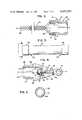
- FIG. 1is a plan view of the grip constructed in accordance with the present invention showing a protective sheath and portions of a mesh grip coupling in section with the upper quarter portion of the protective sheath shown in cross section.
- FIG. 2is an enlarged, longitudinal cross-sectional view of the mesh grip coupling shown in FIG. 1:
- FIG. 3is a longitudinal view of the flexible sheath body portion of the grip shown in FIG. 1 with end caps attached;
- FIG. 4is an enlarged cross-sectional view of the nose end of the protective sheath shown in FIG. 1 depicting a ball-bearing arrangement for providing a low-frictional rotatable mounting for a pulling eyelet, and
- FIG. 5is a plan view of one end of the sheath body and its end cap as shown in FIG. 4.
- a grip constructed in accordance with the present inventionhas particular application to gripping fragile cables and as seen in FIG. 1 comprises a protective sheath 12, a pulling eyelet 14 coupled to one end of the sheath, and a braided or woven open mesh sleeve 16 detachably coupled to the opposite end of the sheath 12.
- the mesh sleeve 16is typically formed from a plurality of interwoven metallic wire strands and is split along the longitudinal axis A--A of the grip as seen in FIG. 1 for receiving a cable (not shown) which is to be gripped by the strands.
- the two loop edgesmay be drawn together about the longitudinal axis A--A and interconnected by a strand 19.
- the sleeveWhen the sleeve is compressed along its longitudinal axis A--A, it increases in size radially to receive a conventional fragile cable with one or more fragile connectors at the end thereof.
- the sleeve 16can be axially stretched which results in a reduction of its size radially into a gripping action on the fragile cable.
- the fragile cablemay be, a fiber optic cable comprising a flexible, resilient jacket encasing a plurality or bundle of individual, hollow glass tubes constituting the optical fibers.
- the fragile connectoris basically a cylindrical member having an internal cylindrical bore for receiving the optical fiber therein, these fibers typically being secured thereto by epoxy as well as a crimp surrounding a short fragile tube extending from the main cylindrical member of the connector.
- a cable of this typeis described in my copending patent application, Ser. No. 340,900 filed Jan.
- the facial end of the connectoris optically finished to receive and transmit the optical signals in the tybes and hence, should be protected from extraneous foreign matter and impacts with obstructions when it is pulled through conduits, passageways and the like.
- the protective sheath 12is comprised of a hollow tubular body 21 having a substantially cylindrical interior chamber 22 which has a forward end 23 and a rearward end 24.
- the diameter of the chamber 22may be large enough to enclose one or more fiber optic cables having a cluster of two or more connectors attached to one end of each cable.
- the sheath body 21is preferably comprised of a flexible hose or conduit which will pass more easily through conduits and passageways which include curvatures such as elbows or bends therein or for any applications where the ability of the sheath to bend or flex in directions transverse to the longitudinal axis is a desired or required feature.
- the sheath bodymay be readily formed from a length A--A of commercially available flexible conduit.
- Such conduitis characterized as having an outer sleeve or covering composed of a synthetic rubber-like plastic material 25 which is resilient, smooth and compressible, and a corrugated inner flexible metallic tube 26 which is concentric about the axis A--A.
- the tube 26is conveniently formed by helically winding a longitudinally corrugated metal strip onto a mandrel such that the adjacent edges of the strip overlap one another to form a continuous, helically seamed joint concentric about the axis A--A.
- the helical jointforms an internal helical groove or female thread which may be threadedly engaged by circumferentially threaded members having male threads thereon of the same pitch and hand as that of the female conduit thread.
- This feature of the metallic conduitis used herein to effect threaded connections between the sheath body 21 and the opposite nose and mesh ends of the sheath.
- the body 21may be obtained by cutting off desired sheath lengths from one or more rolls of commercially-available conduit of appropriate internal diameter. Such ready availability of a suitable component for a major part for the sheath facilitates manufacture of the grip for any desired application.
- the forward end 23 of the sheathincludes an inwardly tapered conical nose 26 which is threadedly coupled to the forward end of the sheath body 21 by an externally threaded hollow ferrule 27.
- the noseis subjected to components of tensile force and is formed of a rigid metal or plastic material which can resist such component forces.
- Formed in the rearward end of the nose 26is an interior cylindrical cavity 35. This cavity is concentric with the longitudinal axis A--A of the nose 26 and is also concentric with a cylindrical bore 37 extending through the nose 26 which is concentric with the axis A--A.
- the noseis provided with a smooth exterior surface to facilitate its movement through conduits, passageways and openings and past other cables which may be contained therein.
- the eyelet 14is formed of a rigid material such as steel, having a shaft 31 mounted in the cylindrical bore 37 for free rotation concentric with the longitudinal axis A--A.
- One or more roller bearings 38are mounted in the cavity and the shaft 31 is rotatably mounted in the bearing 38 against forwardly directed components of tensile forces by a locking cap nut 40 threadedly connected to the threaded distal end 41 of the shaft 31 and abutting the rearward bearing journal 39 of the bearing 38.
- annular disc 42composed of a low-frictional material, such as nylon, is mounted concentrically on the shaft 31 between those parts.
- the nose 26(FIG. 4) is formed with a radially inwardly stepped, circumferential shoulder 28 which extends inwardly from the nose circumference the entire thickness of the sheath body 21 and additionally slightly further inwardly thereof.
- the shoulder 28commences the rearward part of the nose comprising the externally threaded hollow ferrule or coupling 27.
- the ferrule 27has a circumferentially threaded end 29 and an internal chamber 30 of substantially cylindrical shape concentric with the bearing cavity 35.
- the chamber 30has an internal diameter which is slightly less than the internal diameter of the sheath body 21 to accommodate, if necessary, the lead end of the cable inserted into the sheath 12.
- the threaded end 29 of the ferrule 27is typically comprised of a continuous helical male thread having three or four thread convolutions 48 of the same pitch and hand as the internal female thread convolutions 49 formed by the continuous metal corrugations of the sheath body and may be of a modified Acme screw type.
- the outer or pitch diameter of the male thread convolutions 48is only slightly less than the root diameter of the female thread convolutions 49 of the corrugations with which they mate so that a relatively tight threaded connection can be effected between the two threads.
- the nose 26is rotated about the longitudinal axis A--A in an appropriate direction until three or more male thread convolutions 48 are engaged by the female thread convolutions at which point, the shoulder 28 is displaced axially into abutment with an inwardly extending flange 51 of an end cap 52 to secure the end cap 52 in position between the nose and sheath body.
- an annular circumferential stripcan be knurled as indicated by numeral 53.
- the mesh sleeve 16has a lead end 55 and a tail end 56, the mesh lead end 55 thereof being concentrically positioned with respect to the longitudinal axis A--A.
- the end 55is comprised of a hollow, metal ferrule 56 having a hollow, threaded end 58 typically formed by a helical thread having three or four circumferential helical thread convolutions 59 for engaging three or four of the rearwardmost female thread convolutions 49 at the rearwardmost end of the sheath body 10. Because of the female thread provided by these usually has a substantially constant pitch and internal diameter throughout the entire length of the sheath body, the threaded end 58 of the ferrule 56 may be formed with a male thread of the same pitch and hand as on the nose ferrule 27.
- a cylindrical knurled collar 60extends far enough inwardly to abut a flange 63 of an end cap 65 when the ferrule is rotated in an appropriate direction to threadedly engage the three or four female thread convolutions.
- An annular collar 70is mounted on the smooth, exterior surface of rearward section 71 of the ferrule 56, the sleeve ends being sandwiched between the exterior surface of the section 71 and the interior surface of the collar.
- the collar 70rigidly couples the sleeve to the ferrule 56 by means of a swaging operation and extends longitudinally far enough inwardly to abut the end cap 65 when the proper threaded connection is made between the female thread on the sheath body and the male thread on the ferrule 56. So as not to pose any outwardly extending obstruction on the grip, the outer diameter of the collar 70 is slightly less than the outer diameter of the end cap 65.
- forward and rearward ends of the sheath bodyare each constrained against radially outward expansion by the cylindrical cup-shaped end caps 52 and 65, respectively.
- the end caps 52 and 65are essentially identical in size and shape and the inner diameter of each cap is slightly greater than the outer diameter of the respective ends of the sheath body so that the sleeves fit tightly over the ends of the resilient and the radially expandable sheath material at the sheath body ends to prevent any appreciable, radially outward displacement or buckling of these sheath ends and the underlying metallic corrugations.
- the internal diameter of the openings in both flanges 51 and 66is equal to the internal diameter of the sheath body so that the flanges abut the outermost edges of the metal corrugations to constrain the metal corrugations against longitudinal displacement caused by the ferrules exerting outwardly directed forces against these corrugations in response to grip pulling.
- the internal diameter of the opening at the cap flanges 51 and 66is also made slightly greater than the root diameter of the ferrule threads.
- the male threadscan then be rotated past the flanges 51 and 66 of the end caps into threaded engagement with the ferrule threads in the sheath body.
- the end caps 52 and 65will be fixed to the sheath body and, in turn, constrain the metal corrugations against both longitudinal and radial separations and displacements.
- the flanges 51 and 66are abutted by the shoulder 28 and the collar 61, respectively, provided on the ferrules 27 and 56, respectively.
- the mesh sleeve 16is split throughout substantially its entire length, having a series of opposed loops defining the split in the sleeve.
- This embodimentis advantageously used for a plurality of cables with a plurality of connectors at the end thereof which are beyond the regular expansion diameter of a closed sleeve.
- the splitcould also extend up to the collar 61.
- a plurality of fragile cables and connectorscan be maneuvered through the ferrule 56 and into the sheath 12 via the rearward open end of the sheath and received therein.
- the split sleeve 16is wrapped around the cables extending from the sheath 12 and closed, for example, by strand 19 lacing up the opposed series of loops defining the opposed edges of the slit in the sleeve. After lacing is accomplished, the sleeve 16 can be axially stretched which results in a radial compression thereof into a gripping engagement with the cables received therein.
- the strand 19can be of any suitable material such as a flat braided polyester and is advantageously laced by using a conventional lacing needle.
- the sleeve 16may be partly double braided near the ferrule 56 and partly single braided toward its trailing end to enhance the gripping of the small sized cables in the mesh.
- the sheathmay have a large enough internal diameter to accommodate at least three connectors in any positional arrangement.
- a smooth, tubular feed tubemay be used to facilitate the process of inserting the cable longitudinally through the sheath. Since the ferrule 56 can be detached by counter rotation from the rearward end of the sheath body, the detachment of the mesh grip from the sheath body 21 allows the feed tube to pass completely through the frontward open end of the mesh sleeve and the ferrule 56 leaving the connectors free to be manually grasped and inserted into the rearward end of the sheath. The reattachment of the ferrule 56 in the sleeve by appropriate rotation reestablished the threaded union of the grip.
- sheath body 21is disclosed herein as formed of a substantially flexible material a sheath formed of a rigid material may also be provided with a detachable coupling which may be a locking or threaded connection with a detachable coupling, as disclosed herein, to facilitate the process of loading of the cable connectors into the protective sheath body portion, as will be apparent.
Landscapes
- Physics & Mathematics (AREA)
- General Physics & Mathematics (AREA)
- Optics & Photonics (AREA)
- Electric Cable Installation (AREA)
- Light Guides In General And Applications Therefor (AREA)
- Mechanical Coupling Of Light Guides (AREA)
- Optical Fibers, Optical Fiber Cores, And Optical Fiber Bundles (AREA)
- Cable Accessories (AREA)
- Details Of Connecting Devices For Male And Female Coupling (AREA)
Abstract
Description
The present invention relates to a grip for pulling fragile cable and especially fiber optic cable having one or more fragile connectors at the end thereof. The grip includes an elongated, hollow protective sheath open at a rearward end to receive the connector end of the cable, a pulling device coupled at the forward end of the sheath for pulling the sheath, and a mesh sleeve coupled at the rearward end of the sheath for gripping the cable. A portion of the sheath is made flexible to facilitate its movement through conduits and other passageways. The mesh grip is detachably coupled to the rearward end of the sheath to permit its manual removal and facilitate access to the rearward end of the sheath.
Cable grips for pulling, holding and supporting elongated objects such as cables, ropes and the like are well known in the art. These grips typically comprise an open mesh sleeve formed from braided or interwoven metallic wire strands which may be expanded radially by longitudinal compression to enable them to readily receive the cable and radially contracted by longitudinal stretching to frictionally engage the periphery of the cable. Tensile forces tending to separate the grip from the cable or to move the grip along the cable produce a firmer gripping of the cable.
Such grips are suitable for the fairly rugged electrical cable, but significant problems arise when the cable to be pulled is fragile. An example of the latter is fiber optic cable which comprises a flexible jacket encasing a single optical fiber or a bundle of optical fibers therein. Such fragile cable can be easily crushed or its optical characteristics can be distorted if the radial compressive forces on the cable are localized and become too great. Also, the optical fiber can be easily broken when subjected to excessive bending forces. In addition, it is typical to have pre-assembled on the end of fiber optic cable one or more fragile optical connectors receiving one or a bundle of optical fibers therein and secured by an epoxy resin and a crimp. This fragile connector is highly susceptible to crushing radial compressive forces as well as longitudinal tensile forces which could easily snap the connector from the cable. Moreover, the facial end of the connector must be protected from damage which would deleteriously affect its optically finished surface.
Moreover, fiber optic cable is much smaller in diameter than the typical electrical cable. These small diameters in most cases are much less than the conventional wire mesh grips can adequately hold. Also, the fiber optic connector at the end of the fiber optic cable has a much larger outside diameter than the cable so that a conventional grip selected to fit and adequately grip the cable cannot expand enough to accept the larger connector diameter or diameters. Conversely, a grip designed to receive a large diameter connector cannot compress enough to grip the smaller cable diameter. A typical example is a connector with a 0.5 inch outer diameter and a cable with a 0.073 inch outer diameter.
A method presently used to protect a fiber optic cable connector during pulling comprises wrapping the connector in a layer of foam rubber and then inserting this into a plastic sleeve which in turn is inserted into an oversized wire mesh grip. This method, however, is expensive and time consuming since conventional wire mesh grips are relatively stiff, thereby creating extreme difficulty in inserting the small and flexible cable with a connector attached. In addition, after assembly of this combination, the holding capability of the oversized wire mesh is marginal and may allow slippage of the cable and pulling out of the pre-assembled connector.
In addition to these qualifications, a grip for pulling fiber optic cable must adequately grip the cable and not damage the cable or the connector. There are four basic cable configurations that must be contended with by the grip designer. The first is a cable by itself, containing one or a plurality of fiber optic cables all without preassembled connectors. This provides only one rather uniform diameter for the grip to contend with.
A second configuration involves a single fiber optic cable with a preassembled connector, with both the cable and the connector diameter being within the grip diameter range so that the grip can be compressed longitudinally and therefore expand sufficiently in the radial direction to accept the combined cable and connector and also then be stretched longitudinally to thereby reduce the radius of the wire mesh into a sufficient gripping engagement of the cable.
A third cable configuration involves a single fiber optic cable with a preassembled connector where the connector size is beyond the expansion of the wire mesh that is made to suit the cable diameter. Lastly, a fourth basic cable configuration involves a plurality of fiber optic cables with preinstalled conconnectors where the connector diameter build-up is beyond the expansion capability of the wire mesh.
In my copending U.S. patent application Ser. No. 213,856 filed Dec. 8, 1980 and assigned to the same assignee as the instant application, there is disclosed a cable grip which is especially suitable for pulling fiber optic cables and provides the necessary protection to the fragile connector ends of such cables by means of a tubular protective sheath. The particular embodiment of the sheath disclosed in that patent application is one of a rigid metal body formed of, for example, metal tubing. While this particular embodiment of a sheath body provides excellent protection for the fiber optic connector inserted therein, for certain installations involving angled or curved conduits through which the cable must be pulled, a sharp curvature of the conduit walls may pose an obstruction to the passage of an elongated rigid tubular member.
Accordingly, it is an object of the present invention to provide a hollow, elongated sheath having an open, rearward end for receiving and protecting the connector end of a fiber optic cable insertable therein, wherein a portion of the sheath is substantially flexible in directions transverse to its longitudinal axis facilitate its bending around curved conduit walls and the like.
Another object of the present invention is to provide a mesh grip for pulling cable and especially fiber optic cable with at least one fiber optic connector at the end thereof, wherein the grip is readily detachable from an end of a hollow, open-ended sheath protecting the fiber optic connector to facilitate the insertion of the cable connector end into the end of the sheath.
Another object of the present invention is to provide a grip that protects the end of a fragile cable by a flexible, encasing sheath body which utilizes predetermined lengths of commercially available flexible metallic conduit as the sheath body, thereby facilitating the manufacture of the grip.
The foregoing objects are attained in accordance with the instant invention by providing an elongated grip for pulling fragile cable comprising a hollow protective sheath having a forward end and a rearward end and formed in part by a cylindrical midsectional body having a longitudinal axis. The body is designed to be substantially flexible to bending in directions transverse to its longitudinal axis so that the sheath can be snaked through curved conduit walls and other passageways. The sheath body may be formed from several lengths of commercially available longer lengths of flexible metallic conduit or hose which is sold by several manufacturers. Characteristically, this type of conduit sheath is also smooth, pliable and compressible to some extent; all features which make its use particularly suitable for certain pulling grip applications. The rearward end of the sheath is open for the reception of the fragile cable therein.
A tensioning device is rotatably coupled to the forward end of the sheath and wire mesh cable gripping sleeve is readily detachably coupled at its forward end to the sheath. The readily detachable coupling allows quick manual removal of the sleeve from the sheath thereby facilitating on-site loading of a cable connector into the sheath. The detachable coupling of this invention may also be used on formed rigid tubing sheaths, such as disclosed in my aforementioned copending patent application in lieu of swaged couplings which are not normally detachable from the sheath body.
Advantageously, the forward end of the sheath is provided with an inwardly tapered lead for creating an opening for the fiber optic when pulled through a conduit containing a number of existing cables. The pulling device comprises an eyelet rotatably connected at the forward end of the sheath by a low-friction ball bearing to efficiently alleviate torsional stresses on the encased fragile cable during a pulling operation.
Other objects, advantages and salient features of the present invention will become apparent from the following detailed description which, taken in conjunction with the annexed drawings, discloses preferred embodiments of the present invention.
Referring now to the drawings which form a part of this original disclosure:
FIG. 1 is a plan view of the grip constructed in accordance with the present invention showing a protective sheath and portions of a mesh grip coupling in section with the upper quarter portion of the protective sheath shown in cross section.
FIG. 2 is an enlarged, longitudinal cross-sectional view of the mesh grip coupling shown in FIG. 1:
FIG. 3 is a longitudinal view of the flexible sheath body portion of the grip shown in FIG. 1 with end caps attached; and
FIG. 4 is an enlarged cross-sectional view of the nose end of the protective sheath shown in FIG. 1 depicting a ball-bearing arrangement for providing a low-frictional rotatable mounting for a pulling eyelet, and
FIG. 5 is a plan view of one end of the sheath body and its end cap as shown in FIG. 4.
A grip constructed in accordance with the present invention has particular application to gripping fragile cables and as seen in FIG. 1 comprises aprotective sheath 12, a pullingeyelet 14 coupled to one end of the sheath, and a braided or wovenopen mesh sleeve 16 detachably coupled to the opposite end of thesheath 12.
Themesh sleeve 16 is typically formed from a plurality of interwoven metallic wire strands and is split along the longitudinal axis A--A of the grip as seen in FIG. 1 for receiving a cable (not shown) which is to be gripped by the strands. To enclose the grip about a cable placed therein, the two loop edges may be drawn together about the longitudinal axis A--A and interconnected by astrand 19. When the sleeve is compressed along its longitudinal axis A--A, it increases in size radially to receive a conventional fragile cable with one or more fragile connectors at the end thereof. Once suitably placed therein, thesleeve 16 can be axially stretched which results in a reduction of its size radially into a gripping action on the fragile cable.
The fragile cable may be, a fiber optic cable comprising a flexible, resilient jacket encasing a plurality or bundle of individual, hollow glass tubes constituting the optical fibers. The fragile connector is basically a cylindrical member having an internal cylindrical bore for receiving the optical fiber therein, these fibers typically being secured thereto by epoxy as well as a crimp surrounding a short fragile tube extending from the main cylindrical member of the connector. A cable of this type is described in my copending patent application, Ser. No. 340,900 filed Jan. 20, 1982 and assigned to the same assignee as the instant invention and as is known to those working in the fiber optic art, the facial end of the connector is optically finished to receive and transmit the optical signals in the tybes and hence, should be protected from extraneous foreign matter and impacts with obstructions when it is pulled through conduits, passageways and the like.
As seen in FIGS. 1 and 3, theprotective sheath 12 is comprised of a hollowtubular body 21 having a substantially cylindricalinterior chamber 22 which has aforward end 23 and arearward end 24. The diameter of thechamber 22 may be large enough to enclose one or more fiber optic cables having a cluster of two or more connectors attached to one end of each cable.
In accordance with this invention, thesheath body 21 is preferably comprised of a flexible hose or conduit which will pass more easily through conduits and passageways which include curvatures such as elbows or bends therein or for any applications where the ability of the sheath to bend or flex in directions transverse to the longitudinal axis is a desired or required feature.
The sheath body may be readily formed from a length A--A of commercially available flexible conduit. Such conduit is characterized as having an outer sleeve or covering composed of a synthetic rubber-like plastic material 25 which is resilient, smooth and compressible, and a corrugated inner flexiblemetallic tube 26 which is concentric about the axis A--A. Thetube 26 is conveniently formed by helically winding a longitudinally corrugated metal strip onto a mandrel such that the adjacent edges of the strip overlap one another to form a continuous, helically seamed joint concentric about the axis A--A. The helical joint forms an internal helical groove or female thread which may be threadedly engaged by circumferentially threaded members having male threads thereon of the same pitch and hand as that of the female conduit thread. This feature of the metallic conduit is used herein to effect threaded connections between thesheath body 21 and the opposite nose and mesh ends of the sheath. In addition, thebody 21 may be obtained by cutting off desired sheath lengths from one or more rolls of commercially-available conduit of appropriate internal diameter. Such ready availability of a suitable component for a major part for the sheath facilitates manufacture of the grip for any desired application.
Theforward end 23 of the sheath includes an inwardly taperedconical nose 26 which is threadedly coupled to the forward end of thesheath body 21 by an externally threadedhollow ferrule 27. The nose is subjected to components of tensile force and is formed of a rigid metal or plastic material which can resist such component forces. Formed in the rearward end of the nose 26 (FIGS. 1 and 4) is an interiorcylindrical cavity 35. This cavity is concentric with the longitudinal axis A--A of thenose 26 and is also concentric with acylindrical bore 37 extending through thenose 26 which is concentric with the axis A--A. The nose is provided with a smooth exterior surface to facilitate its movement through conduits, passageways and openings and past other cables which may be contained therein.
Theeyelet 14 is formed of a rigid material such as steel, having ashaft 31 mounted in the cylindrical bore 37 for free rotation concentric with the longitudinal axis A--A. One ormore roller bearings 38 are mounted in the cavity and theshaft 31 is rotatably mounted in thebearing 38 against forwardly directed components of tensile forces by a lockingcap nut 40 threadedly connected to the threadeddistal end 41 of theshaft 31 and abutting the rearward bearingjournal 39 of thebearing 38. With theeyelet 14 attached to a rope, line or other pulling means, thenose 26 can unwind relatively freely while under tensile loading as a result of turning movements imparted to the sheath by a torsionally-stressed fiber optic cable or by the pulling line. Theforward journal 43 of thebearing 38 is seated against the bottom wall of thecavity 35 adjacent thebore 37 so thenut 40 and theeyelet shaft 31 cannot be pulled forwardly and away from thesheath 12 under tensile loading. As a buffer against significant frictional engagement between theeyelet 14 andnose 26, anannular disc 42 composed of a low-frictional material, such as nylon, is mounted concentrically on theshaft 31 between those parts.
The nose 26 (FIG. 4) is formed with a radially inwardly stepped,circumferential shoulder 28 which extends inwardly from the nose circumference the entire thickness of thesheath body 21 and additionally slightly further inwardly thereof. Theshoulder 28 commences the rearward part of the nose comprising the externally threaded hollow ferrule orcoupling 27. Theferrule 27 has a circumferentially threadedend 29 and aninternal chamber 30 of substantially cylindrical shape concentric with the bearingcavity 35. Thechamber 30 has an internal diameter which is slightly less than the internal diameter of thesheath body 21 to accommodate, if necessary, the lead end of the cable inserted into thesheath 12.
The threadedend 29 of theferrule 27 is typically comprised of a continuous helical male thread having three or fourthread convolutions 48 of the same pitch and hand as the internalfemale thread convolutions 49 formed by the continuous metal corrugations of the sheath body and may be of a modified Acme screw type. The outer or pitch diameter of themale thread convolutions 48 is only slightly less than the root diameter of thefemale thread convolutions 49 of the corrugations with which they mate so that a relatively tight threaded connection can be effected between the two threads. Thenose 26 is rotated about the longitudinal axis A--A in an appropriate direction until three or moremale thread convolutions 48 are engaged by the female thread convolutions at which point, theshoulder 28 is displaced axially into abutment with an inwardly extendingflange 51 of anend cap 52 to secure theend cap 52 in position between the nose and sheath body. To facilitate manual turning of thenose 26, an annular circumferential strip can be knurled as indicated bynumeral 53.
As seen in FIG. 2, themesh sleeve 16 has alead end 55 and atail end 56, the meshlead end 55 thereof being concentrically positioned with respect to the longitudinal axis A--A.
Theend 55 is comprised of a hollow,metal ferrule 56 having a hollow, threadedend 58 typically formed by a helical thread having three or four circumferentialhelical thread convolutions 59 for engaging three or four of the rearwardmostfemale thread convolutions 49 at the rearwardmost end of the sheath body 10. Because of the female thread provided by these usually has a substantially constant pitch and internal diameter throughout the entire length of the sheath body, the threadedend 58 of theferrule 56 may be formed with a male thread of the same pitch and hand as on thenose ferrule 27.
To provide an abutting shoulder essentially equivalent to theshoulder 28, the forwardmost end of a cylindrical knurled collar 60 extends far enough inwardly to abut a flange 63 of anend cap 65 when the ferrule is rotated in an appropriate direction to threadedly engage the three or four female thread convolutions.
Anannular collar 70 is mounted on the smooth, exterior surface ofrearward section 71 of theferrule 56, the sleeve ends being sandwiched between the exterior surface of thesection 71 and the interior surface of the collar. Thecollar 70 rigidly couples the sleeve to theferrule 56 by means of a swaging operation and extends longitudinally far enough inwardly to abut theend cap 65 when the proper threaded connection is made between the female thread on the sheath body and the male thread on theferrule 56. So as not to pose any outwardly extending obstruction on the grip, the outer diameter of thecollar 70 is slightly less than the outer diameter of theend cap 65.
As mentioned briefly hereinabove, forward and rearward ends of the sheath body are each constrained against radially outward expansion by the cylindrical cup-shaped end caps 52 and 65, respectively. The end caps 52 and 65 are essentially identical in size and shape and the inner diameter of each cap is slightly greater than the outer diameter of the respective ends of the sheath body so that the sleeves fit tightly over the ends of the resilient and the radially expandable sheath material at the sheath body ends to prevent any appreciable, radially outward displacement or buckling of these sheath ends and the underlying metallic corrugations.
Such radially outward displacement of the sheath body ends. might otherwise develop when radially-outwardly directed components of forces are developed and applied against the internal thread surfaces of the corrugations by the inclined ferrule thread convolutions bearing thereagainst when the grip is pulled longitudinally. The radially, inwardly-extendingflanges caps flanges
To permit longitudinal insertion of each threaded ferrule end through its corresponding end cap, the internal diameter of the opening at thecap flanges flanges flanges shoulder 28 and thecollar 61, respectively, provided on theferrules
In the illustrated embodiment of this invention, themesh sleeve 16 is split throughout substantially its entire length, having a series of opposed loops defining the split in the sleeve. This embodiment is advantageously used for a plurality of cables with a plurality of connectors at the end thereof which are beyond the regular expansion diameter of a closed sleeve. The split could also extend up to thecollar 61.
With the loops separated, a plurality of fragile cables and connectors can be maneuvered through theferrule 56 and into thesheath 12 via the rearward open end of the sheath and received therein. Thesplit sleeve 16 is wrapped around the cables extending from thesheath 12 and closed, for example, bystrand 19 lacing up the opposed series of loops defining the opposed edges of the slit in the sleeve. After lacing is accomplished, thesleeve 16 can be axially stretched which results in a radial compression thereof into a gripping engagement with the cables received therein. Thestrand 19 can be of any suitable material such as a flat braided polyester and is advantageously laced by using a conventional lacing needle. Thesleeve 16 may be partly double braided near theferrule 56 and partly single braided toward its trailing end to enhance the gripping of the small sized cables in the mesh. The sheath may have a large enough internal diameter to accommodate at least three connectors in any positional arrangement.
With partially or fully closed mesh grips, a smooth, tubular feed tube may be used to facilitate the process of inserting the cable longitudinally through the sheath. Since theferrule 56 can be detached by counter rotation from the rearward end of the sheath body, the detachment of the mesh grip from thesheath body 21 allows the feed tube to pass completely through the frontward open end of the mesh sleeve and theferrule 56 leaving the connectors free to be manually grasped and inserted into the rearward end of the sheath. The reattachment of theferrule 56 in the sleeve by appropriate rotation reestablished the threaded union of the grip. Although thesheath body 21 is disclosed herein as formed of a substantially flexible material a sheath formed of a rigid material may also be provided with a detachable coupling which may be a locking or threaded connection with a detachable coupling, as disclosed herein, to facilitate the process of loading of the cable connectors into the protective sheath body portion, as will be apparent.
While one advantageous embodiment has been chosen to illustrate the invention, it will be understood by those skilled in the art that various changes and modifications can be made therein without departing from the scope of the invention as defined in the appended claims.
Claims (16)
1. A grip for elongated objects such as cables and the like, comprising:
a tubular body for housing one end of the object, said body having opposite forward and rearward end portions and a longitudinal axis and being elongated in a direction parallel to said axis,
said body including a substantially flexible wall portion between said forward and rearward end portions for bending in directions transverse to said longitudinal axis and providing therein a chamber elongated in a direction parallel to said longitudinal axis and having an open end communicating with the rearward end portion of said body,
means coupled to the forward end portion of said body for applying tensile force to said body; and
a gripping device coupled to the rearward end portion of said body for holding the object in said chamber while tensile force is applied to said means.
2. The grip as claimed in claim 1 wherein said tubular body comprises an outer sleeve of a substantially flexible material and an inner winding disposed substantially helically about said longitudinal axis.
3. The grip as claimed in claim 2 wherein said gripping device includes a hollow, threaded end portion for threadedly engaging the inner helical winding on the rearward portion of said body.
4. The grip as claimed in claim 3 wherein the inner helical winding of said body forms a female thread and wherein said threaded end portion of said gripping device has a male thread thereon for threadedly engaging the female thread on said body.
5. The grip as claimed in claim 1 wherein said grip includes an inwardly tapering nose portion joined to the forward end of said body and wherein said means is rotatably coupled to said nose portion.
6. The grip as claimed in claim 5 wherein said means comprises an elongated shaft extending into said nose portion substantially concentric with the longitudinal axis of said body, and a ball bearing mounted in said nose portion for mounting said shaft for rotation about said longitudinal axis.
7. The grip as claimed in claims 1 or 2 wherein said gripping device is detachably coupled to said rearward end portion of said body.
8. The grip as claimed in claim 7 wherein said gripping device comprises an open mesh sleeve which surrounds portions of the object and contracts inwardly to grip such portions when the body is pulled forwardly by said means.
9. The grip as claimed in claim 8 wherein said rearward end of said body includes an internally threaded portion and wherein said gripping device includes an externally threaded portion for threadedly engaging said internally threaded portion of said gripping device.
10. The grip as claimed in claim 9 wherein said externally threaded portion of said gripping device includes a circumferential shoulder for restraining the rearwardmost inner winding of said tubular body against longitudinal, rearward displacement.
11. A grip for elongated objects such as cables and the like, comprising:
a hollow, tubular body having opposite forward and rearward end portions and a longitudinal axis and being elongated in a direction parallel to said axis, said body providing therein an elongated chamber having an open end communicating with the rearward end portion of said body for receiving one end of the body;
means coupled to the forward end portion of said body for applying tension to said body in generally forward directions,
a gripping device coupled to the rearward portion of said body for gripping the object when the body is tensioned by said means, and
means for detachably coupling said gripping device to said rearward portion of said body.
12. The grip as claimed in claim 11 wherein said tubular rearward portion of said body comprises a threaded section and wherein said gripping device includes a forward threaded end section threadedly engaging the rearward threaded section of said body.
13. The grip as claimed in claim 12 wherein said threaded section of said body comprises an inner metallic corrugation forming a helical female thread and wherein said threaded end section of said gripping device comprises a ferrule having a male thread thereon for threadedly engaging said female thread.
14. Apparatus for gripping elongated objects such as cables and the like, comprising:
an open mesh sleeve for gripping the object inserted therein, said sleeve having respective draft and trailing end portions;
a flexible, hollow sheath having respective draft and trailing ends, the trailing sheath end rotatably coupled to the draft end portion for applying a tensile force component to said mesh sleeve, said sheath circumferentially enclosing one end of the gripped object; and
means for manually detachably coupling the trailing end of said sheath to said draft end portion of said mesh sleeve.
15. The apparatus as claimed in claim 14 wherein the coupling means comprises a rotatable coupling.
16. The apparatus as claimed in claim 15 wherein the rotatable coupling comprises mating male and female threaded members.
Priority Applications (6)
| Application Number | Priority Date | Filing Date | Title |
|---|---|---|---|
| US06/390,307US4453291A (en) | 1982-06-21 | 1982-06-21 | Grip for pulling fiber optic cable |
| CA000425684ACA1220326A (en) | 1982-06-21 | 1983-04-12 | Grip for pulling fiber optic cable |
| GB08311226AGB2122318B (en) | 1982-06-21 | 1983-04-25 | Grip for pulling fibre optic cable |
| JP58101834AJPS595204A (en) | 1982-06-21 | 1983-06-09 | Grip apparatus |
| FR8309767AFR2532027B1 (en) | 1982-06-21 | 1983-06-13 | TIGHTENING AND TENSIONING DEVICE FOR FRAGILE CABLES, PARTICULARLY FOR OPTICAL FIBER CABLES |
| DE3322104ADE3322104C2 (en) | 1982-06-21 | 1983-06-20 | Pulling head for cables or the like |
Applications Claiming Priority (1)
| Application Number | Priority Date | Filing Date | Title |
|---|---|---|---|
| US06/390,307US4453291A (en) | 1982-06-21 | 1982-06-21 | Grip for pulling fiber optic cable |
Publications (1)
| Publication Number | Publication Date |
|---|---|
| US4453291Atrue US4453291A (en) | 1984-06-12 |
Family
ID=23541959
Family Applications (1)
| Application Number | Title | Priority Date | Filing Date |
|---|---|---|---|
| US06/390,307Expired - LifetimeUS4453291A (en) | 1982-06-21 | 1982-06-21 | Grip for pulling fiber optic cable |
Country Status (6)
| Country | Link |
|---|---|
| US (1) | US4453291A (en) |
| JP (1) | JPS595204A (en) |
| CA (1) | CA1220326A (en) |
| DE (1) | DE3322104C2 (en) |
| FR (1) | FR2532027B1 (en) |
| GB (1) | GB2122318B (en) |
Cited By (52)
| Publication number | Priority date | Publication date | Assignee | Title |
|---|---|---|---|---|
| US4600331A (en)* | 1985-06-19 | 1986-07-15 | Harvey Hubbell Incorporated | Swivel coupling |
| US4657343A (en)* | 1982-10-06 | 1987-04-14 | Standard Telephones And Cables, Public Limited Company | Optical fiber cable and method of jointing two cable elements |
| US5013125A (en)* | 1989-10-02 | 1991-05-07 | Alcatel Na Cable Systems Inc. | Pulling eye assembly for connectorized optical fiber cables |
| US5133583A (en)* | 1989-04-27 | 1992-07-28 | Siecor Corporation | Method for use of mesh type cable pulling grips |
| US5810022A (en)* | 1997-10-10 | 1998-09-22 | Reynolds; Anne L. | Device and method for the holding of and the covering of the ends of braids with attachable decorative or ornamental assembly |
| US6629685B2 (en) | 2001-03-16 | 2003-10-07 | Roy E. Bowling | Method and apparatus for pulling wire |
| US20040041136A1 (en)* | 2002-08-30 | 2004-03-04 | Ames William Mathew | Cable clamping apparatus and method |
| US20050051170A1 (en)* | 2003-09-09 | 2005-03-10 | Koo Myung Hoe | Wearable inhalation filter |
| US7478794B1 (en) | 2006-09-26 | 2009-01-20 | Rectorseal Corporation | Apparatus and methods for gripping an elongated item |
| US20090123115A1 (en)* | 2007-10-09 | 2009-05-14 | Erik Gronvall | Drop Terminal Releasable Engagement Mechanism |
| US20090224220A1 (en)* | 2008-03-05 | 2009-09-10 | David Jordan | Device for gripping and installing wire |
| US20090238534A1 (en)* | 2008-02-29 | 2009-09-24 | Adc Telecommunications, Inc. | Cable pulling assembly |
| US20090310923A1 (en)* | 2003-12-29 | 2009-12-17 | Adc Telecommunications, Inc. | Telecommunications connector protective device |
| US20100051886A1 (en)* | 2008-08-29 | 2010-03-04 | Cooke Terry L | Pulling Grip Assembly for a Fiber Optic Assembly |
| US20100258771A1 (en)* | 2009-04-09 | 2010-10-14 | White Christopher L | Wire pull assembly |
| US7844158B2 (en) | 2007-10-09 | 2010-11-30 | Adc Telecommunications, Inc. | Mini drop terminal |
| US20100316347A1 (en)* | 2009-05-13 | 2010-12-16 | Adc Telecommunications, Inc. | Cable pulling assembly |
| US20100329610A1 (en)* | 2007-09-05 | 2010-12-30 | Adc Telecommunications Inc. | Connector enclosure |
| US20110135268A1 (en)* | 2009-11-25 | 2011-06-09 | Adc Telecommunications, Inc. | Cable pulling assembly |
| US20120090145A1 (en)* | 2010-10-15 | 2012-04-19 | John Mezzalingua Associates Inc. | Elongate member attachment apparatus and method of use thereof |
| USRE43762E1 (en) | 2004-03-08 | 2012-10-23 | Adc Telecommunications, Inc. | Fiber access terminal |
| US8757594B2 (en) | 2008-10-23 | 2014-06-24 | Southwire Company, Llc | Pulling jacket for use while installing wires in conduit |
| US8831395B2 (en) | 2011-11-14 | 2014-09-09 | Adc Telecommunications, Inc. | Cable pulling arrangement |
| US20150158706A1 (en)* | 2013-11-11 | 2015-06-11 | Richard E. Vogt | Linear Line Brake |
| US20160139355A1 (en)* | 2014-10-27 | 2016-05-19 | Commscope Technologies Llc | Fiber optic cable with flexible conduit |
| US9537293B2 (en) | 2012-02-29 | 2017-01-03 | Encore Wire Corporation | Wire pulling head apparatus with crimp zone indicators and method of using same |
| US9684144B2 (en) | 2012-09-28 | 2017-06-20 | Commscope Technologies Llc | Rapid deployment packaging for optical fiber |
| US9885847B2 (en) | 2009-05-08 | 2018-02-06 | Commscope Technologies Llc | Cable pulling assembly |
| US20180067275A1 (en)* | 2016-09-02 | 2018-03-08 | Belden Canada Inc. | Optic cable puller assembly |
| CN108599015A (en)* | 2018-04-24 | 2018-09-28 | 安徽春辉仪表线缆集团有限公司 | A kind of cable drum that reliability is high traction fixture |
| US10175430B2 (en) | 2016-05-05 | 2019-01-08 | Belden Canada Inc. | Overmoulded furcation assembly with strain relief |
| USD842670S1 (en) | 2017-10-30 | 2019-03-12 | Derek M. Rose | Universal cable installation tool |
| US10281005B2 (en) | 2015-05-29 | 2019-05-07 | Commscope Technologies Llc | Cable pulling assembly |
| US10437002B2 (en) | 2016-11-09 | 2019-10-08 | Derek M. Rose | Universal cable installation tool |
| KR20190119443A (en)* | 2018-04-12 | 2019-10-22 | 주식회사 동아특수건설 | Tie cable binding device and its construction method |
| KR20200030544A (en)* | 2017-06-21 | 2020-03-20 | 씨-링 리미티드 | Inlet head assembly |
| US10606019B2 (en) | 2015-07-31 | 2020-03-31 | Commscope Technologies Australia Pty Ltd | Cable breakout assembly |
| US10797474B1 (en)* | 2013-04-29 | 2020-10-06 | Clarence Hall | Fish tape leader |
| US10890730B2 (en) | 2016-08-31 | 2021-01-12 | Commscope Technologies Llc | Fiber optic cable clamp and clamp assembly |
| US10914909B2 (en) | 2016-10-13 | 2021-02-09 | Commscope Technologies Llc | Fiber optic breakout transition assembly incorporating epoxy plug and cable strain relief |
| US20210241936A1 (en)* | 2020-02-04 | 2021-08-05 | Structured Home Wiring Direct, LLC | Composite Hybrid Cables and Methods of Manufacturing and Installing the Same |
| US11131821B2 (en) | 2016-03-18 | 2021-09-28 | Commscope Technologies Llc | Optic fiber cable fanout conduit arrangements; components, and methods |
| US11131822B2 (en) | 2017-05-08 | 2021-09-28 | Commscope Technologies Llc | Fiber-optic breakout transition assembly |
| WO2021262153A1 (en)* | 2020-06-23 | 2021-12-30 | Luca Zanetti | Spmcc sleeve to pass multiple connectors into conduits |
| US11404854B2 (en) | 2017-06-21 | 2022-08-02 | C-Ling Limited | Pull-in head assembly |
| US11418016B2 (en) | 2017-06-21 | 2022-08-16 | C-Ling Limited | Pull-in head assembly |
| US11703653B2 (en) | 2021-03-04 | 2023-07-18 | Corning Research & Development Corporation | Pulling grip assembly for cables and related methods |
| US20230291184A1 (en)* | 2020-08-06 | 2023-09-14 | Mes Bros. B.V. | Coupling device and method for pulling an electrical wire through a conduit |
| US11774697B2 (en) | 2020-11-24 | 2023-10-03 | Corning Research & Development Corporation | Fiber optic cable assembly with pulling grip assembly and related methods |
| US11906805B2 (en) | 2020-10-16 | 2024-02-20 | Corning Research & Development Corporation | Fiber optic cable assembly with pulling grip assembly |
| US20240061190A1 (en)* | 2022-08-17 | 2024-02-22 | Corning Research & Development Corporation | Fiber optic cable with pull grip and method of making and using same |
| USD1077602S1 (en)* | 2021-06-11 | 2025-06-03 | Milwaukee Electric Tool Corporation | Socket extension |
Families Citing this family (10)
| Publication number | Priority date | Publication date | Assignee | Title |
|---|---|---|---|---|
| DE3414611A1 (en)* | 1984-04-18 | 1985-10-24 | AEG-Telefunken Kabelwerke AG, Rheydt, 4050 Mönchengladbach | High-tensile capping for an optical cable |
| DE3605389A1 (en)* | 1986-02-20 | 1987-08-27 | Philips Patentverwaltung | End, which is provided with pull-in capping, of, in particular, an optical cable |
| DE8708258U1 (en)* | 1987-06-11 | 1988-04-07 | Heidelberger Druckmaschinen Ag, 69115 Heidelberg | Protection device for one cable end |
| JPH0171912U (en)* | 1987-11-02 | 1989-05-15 | ||
| GB2470584B (en)* | 2009-05-28 | 2013-12-18 | Connectix Ltd | Cable end unit |
| JP6083087B2 (en)* | 2012-06-15 | 2017-02-22 | 株式会社オーシーシー | End structure of optical fiber cable, method for manufacturing end structure |
| JP2015075639A (en)* | 2013-10-09 | 2015-04-20 | 住友電気工業株式会社 | Optical cable |
| AT515474B1 (en)* | 2014-03-07 | 2015-11-15 | Haslacher & Haslacher Immobilien & Patentverwaltungs Gmbh | Device for pulling in cables |
| CN105811321B (en)* | 2016-05-13 | 2017-09-01 | 中天科技海缆有限公司 | A kind of dynamic complex cable pulling protects head |
| CN107435788A (en)* | 2017-08-10 | 2017-12-05 | 安徽英冉信息咨询有限公司 | A kind of strong Web Hosting information displaying distributing device of stability |
Citations (18)
| Publication number | Priority date | Publication date | Assignee | Title |
|---|---|---|---|---|
| US1686250A (en)* | 1927-07-07 | 1928-10-02 | Herbert E Page | Cable grip |
| US1807993A (en)* | 1929-10-04 | 1931-06-02 | Philip J Martin | Cable grip |
| US1994674A (en)* | 1933-09-01 | 1935-03-19 | Bell Telephone Labor Inc | Cable grip |
| US2017625A (en)* | 1933-11-20 | 1935-10-15 | Kellems Products Inc | Cable grip |
| US2112281A (en)* | 1936-05-02 | 1938-03-29 | Starline | Grip for manila rope and the like |
| US2327831A (en)* | 1942-11-24 | 1943-08-24 | Bell Telephone Labor Inc | Cable pulling attachment |
| GB627278A (en)* | 1947-02-22 | 1949-08-04 | Samuel James Everett | Improvements relating to flexible tubular pipe connectors, stoppers and closure caps |
| US2602207A (en)* | 1949-01-18 | 1952-07-08 | Kellems Company | Cable grip |
| US2642767A (en)* | 1951-01-09 | 1953-06-23 | Harold Oakley Woolley Jr | Adjustable holding device for fishhooks, etc. |
| US2698150A (en)* | 1951-06-08 | 1954-12-28 | Palma Joseph Di | Cable grip |
| US2740178A (en)* | 1951-05-26 | 1956-04-03 | Kellems Company | Cable luffing grips |
| US2766501A (en)* | 1951-05-22 | 1956-10-16 | Kellems Company | Cable grips |
| US3343231A (en)* | 1964-12-31 | 1967-09-26 | Kellems Company Inc | Mechanical holding device |
| US3431947A (en)* | 1966-05-13 | 1969-03-11 | Vernon C Hines | Safety harness for flexible hose and the like |
| US3551959A (en)* | 1968-05-16 | 1971-01-05 | Fanner Mfg Co | Detachable socketed dead end |
| US3570074A (en)* | 1968-11-12 | 1971-03-16 | Westinghouse Electric Corp | Rope end fitting |
| US4055875A (en)* | 1976-05-24 | 1977-11-01 | General Dynamics Corporation | Cable gripping device |
| US4368910A (en)* | 1980-12-08 | 1983-01-18 | Harvey Hubbell Incorporated | Grip for pulling fiber optic cable and method of inserting the cable into the grip |
Family Cites Families (8)
| Publication number | Priority date | Publication date | Assignee | Title |
|---|---|---|---|---|
| GB230161A (en)* | 1923-12-03 | 1925-03-03 | Joseph Grove | Improvements in automatic adjustable holder for candles, electric lamps and the like |
| GB496460A (en)* | 1938-04-19 | 1938-11-30 | Ernest Christian Gebbs | Improvements in and relating to grips for ropes, wires and the like |
| US2509115A (en)* | 1946-07-13 | 1950-05-23 | William H Wait | Fish tape leader |
| GB940799A (en)* | 1960-04-11 | 1963-11-06 | Cable Covers Ltd | Improvements in and relating to post-tensioning of concrete |
| US3346284A (en)* | 1965-03-30 | 1967-10-10 | Petersen Anita E | Swivel cable pulling grip and filler |
| BE751006A (en)* | 1969-06-02 | 1970-11-03 | Zafira France | SELF-TENSIONING FOR CABLE |
| DE1929127A1 (en)* | 1969-06-09 | 1970-12-23 | Jakob Thaler | Device for pulling wires, ropes or the like. |
| DE8211359U1 (en)* | 1982-04-21 | 1982-08-19 | Peter Lancier Maschinenbau-Hafenhütte GmbH & Co KG, 4400 Münster | Pulling head for coaxial cables |
- 1982
- 1982-06-21USUS06/390,307patent/US4453291A/ennot_activeExpired - Lifetime
- 1983
- 1983-04-12CACA000425684Apatent/CA1220326A/ennot_activeExpired
- 1983-04-25GBGB08311226Apatent/GB2122318B/ennot_activeExpired
- 1983-06-09JPJP58101834Apatent/JPS595204A/enactivePending
- 1983-06-13FRFR8309767Apatent/FR2532027B1/ennot_activeExpired
- 1983-06-20DEDE3322104Apatent/DE3322104C2/ennot_activeExpired
Patent Citations (18)
| Publication number | Priority date | Publication date | Assignee | Title |
|---|---|---|---|---|
| US1686250A (en)* | 1927-07-07 | 1928-10-02 | Herbert E Page | Cable grip |
| US1807993A (en)* | 1929-10-04 | 1931-06-02 | Philip J Martin | Cable grip |
| US1994674A (en)* | 1933-09-01 | 1935-03-19 | Bell Telephone Labor Inc | Cable grip |
| US2017625A (en)* | 1933-11-20 | 1935-10-15 | Kellems Products Inc | Cable grip |
| US2112281A (en)* | 1936-05-02 | 1938-03-29 | Starline | Grip for manila rope and the like |
| US2327831A (en)* | 1942-11-24 | 1943-08-24 | Bell Telephone Labor Inc | Cable pulling attachment |
| GB627278A (en)* | 1947-02-22 | 1949-08-04 | Samuel James Everett | Improvements relating to flexible tubular pipe connectors, stoppers and closure caps |
| US2602207A (en)* | 1949-01-18 | 1952-07-08 | Kellems Company | Cable grip |
| US2642767A (en)* | 1951-01-09 | 1953-06-23 | Harold Oakley Woolley Jr | Adjustable holding device for fishhooks, etc. |
| US2766501A (en)* | 1951-05-22 | 1956-10-16 | Kellems Company | Cable grips |
| US2740178A (en)* | 1951-05-26 | 1956-04-03 | Kellems Company | Cable luffing grips |
| US2698150A (en)* | 1951-06-08 | 1954-12-28 | Palma Joseph Di | Cable grip |
| US3343231A (en)* | 1964-12-31 | 1967-09-26 | Kellems Company Inc | Mechanical holding device |
| US3431947A (en)* | 1966-05-13 | 1969-03-11 | Vernon C Hines | Safety harness for flexible hose and the like |
| US3551959A (en)* | 1968-05-16 | 1971-01-05 | Fanner Mfg Co | Detachable socketed dead end |
| US3570074A (en)* | 1968-11-12 | 1971-03-16 | Westinghouse Electric Corp | Rope end fitting |
| US4055875A (en)* | 1976-05-24 | 1977-11-01 | General Dynamics Corporation | Cable gripping device |
| US4368910A (en)* | 1980-12-08 | 1983-01-18 | Harvey Hubbell Incorporated | Grip for pulling fiber optic cable and method of inserting the cable into the grip |
Cited By (93)
| Publication number | Priority date | Publication date | Assignee | Title |
|---|---|---|---|---|
| US4657343A (en)* | 1982-10-06 | 1987-04-14 | Standard Telephones And Cables, Public Limited Company | Optical fiber cable and method of jointing two cable elements |
| US4600331A (en)* | 1985-06-19 | 1986-07-15 | Harvey Hubbell Incorporated | Swivel coupling |
| US5133583A (en)* | 1989-04-27 | 1992-07-28 | Siecor Corporation | Method for use of mesh type cable pulling grips |
| US5013125A (en)* | 1989-10-02 | 1991-05-07 | Alcatel Na Cable Systems Inc. | Pulling eye assembly for connectorized optical fiber cables |
| US5810022A (en)* | 1997-10-10 | 1998-09-22 | Reynolds; Anne L. | Device and method for the holding of and the covering of the ends of braids with attachable decorative or ornamental assembly |
| US6719274B2 (en) | 2001-03-16 | 2004-04-13 | Roy E. Bowling | Method and apparatus for pulling wire |
| US6629685B2 (en) | 2001-03-16 | 2003-10-07 | Roy E. Bowling | Method and apparatus for pulling wire |
| US20050242331A1 (en)* | 2002-08-30 | 2005-11-03 | Ames William M | Cable clamping apparatus and method |
| US6883782B2 (en) | 2002-08-30 | 2005-04-26 | Bendyco Incorporated | Cable clamping apparatus and method |
| US20060011899A1 (en)* | 2002-08-30 | 2006-01-19 | Bendyco Incorporated | Cable clamping apparatus and method |
| US7128306B2 (en) | 2002-08-30 | 2006-10-31 | Rectorseal Corporation | Cable clamping apparatus and method |
| US7246789B2 (en) | 2002-08-30 | 2007-07-24 | Rectorseal Corporation | Cable clamping apparatus and method |
| US20040041136A1 (en)* | 2002-08-30 | 2004-03-04 | Ames William Mathew | Cable clamping apparatus and method |
| US20050051170A1 (en)* | 2003-09-09 | 2005-03-10 | Koo Myung Hoe | Wearable inhalation filter |
| US8126307B2 (en) | 2003-12-29 | 2012-02-28 | Adc Telecommunications, Inc. | Telecommunications connector protective device |
| US20090310923A1 (en)* | 2003-12-29 | 2009-12-17 | Adc Telecommunications, Inc. | Telecommunications connector protective device |
| USRE43762E1 (en) | 2004-03-08 | 2012-10-23 | Adc Telecommunications, Inc. | Fiber access terminal |
| US7934697B2 (en) | 2006-09-26 | 2011-05-03 | Rectorseal Corporation | Apparatus and methods for gripping an elongated item |
| US7478794B1 (en) | 2006-09-26 | 2009-01-20 | Rectorseal Corporation | Apparatus and methods for gripping an elongated item |
| US20090070966A1 (en)* | 2006-09-26 | 2009-03-19 | Rectorseal Corporation | Apparatus and methods for gripping an elongated item |
| US20100329610A1 (en)* | 2007-09-05 | 2010-12-30 | Adc Telecommunications Inc. | Connector enclosure |
| US8272787B2 (en) | 2007-09-05 | 2012-09-25 | Adc Telecommunications, Inc. | Connector enclosure |
| US7903923B2 (en) | 2007-10-09 | 2011-03-08 | Adc Telecommunications, Inc. | Drop terminal releasable engagement mechanism |
| US8213761B2 (en) | 2007-10-09 | 2012-07-03 | Adc Telecommunications | Mini drop terminal |
| US20110067452A1 (en)* | 2007-10-09 | 2011-03-24 | Adc Telecommunications, Inc. | Mini drop terminal |
| US7844158B2 (en) | 2007-10-09 | 2010-11-30 | Adc Telecommunications, Inc. | Mini drop terminal |
| US20090123115A1 (en)* | 2007-10-09 | 2009-05-14 | Erik Gronvall | Drop Terminal Releasable Engagement Mechanism |
| US8385712B2 (en) | 2008-02-29 | 2013-02-26 | Adc Telecommunications, Inc. | Cable pulling assembly |
| US20090238534A1 (en)* | 2008-02-29 | 2009-09-24 | Adc Telecommunications, Inc. | Cable pulling assembly |
| US20090224220A1 (en)* | 2008-03-05 | 2009-09-10 | David Jordan | Device for gripping and installing wire |
| US8292267B2 (en) | 2008-03-05 | 2012-10-23 | Southwire Company | Device for gripping and installing wire |
| US20100051886A1 (en)* | 2008-08-29 | 2010-03-04 | Cooke Terry L | Pulling Grip Assembly for a Fiber Optic Assembly |
| US8944411B2 (en)* | 2008-08-29 | 2015-02-03 | Corning Cable Systems Llc | Pulling grip assembly for a fiber optic assembly |
| US8757594B2 (en) | 2008-10-23 | 2014-06-24 | Southwire Company, Llc | Pulling jacket for use while installing wires in conduit |
| US8091866B2 (en)* | 2009-04-09 | 2012-01-10 | Christopher L White | Wire pull assembly |
| US20100258771A1 (en)* | 2009-04-09 | 2010-10-14 | White Christopher L | Wire pull assembly |
| US9885847B2 (en) | 2009-05-08 | 2018-02-06 | Commscope Technologies Llc | Cable pulling assembly |
| US10598886B2 (en) | 2009-05-08 | 2020-03-24 | Commscope Technologies Llc | Cable pulling assembly |
| US20100316347A1 (en)* | 2009-05-13 | 2010-12-16 | Adc Telecommunications, Inc. | Cable pulling assembly |
| US8412017B2 (en) | 2009-05-13 | 2013-04-02 | Adc Telecommunications, Inc. | Cable pulling assembly |
| US20110135268A1 (en)* | 2009-11-25 | 2011-06-09 | Adc Telecommunications, Inc. | Cable pulling assembly |
| US8620129B2 (en) | 2009-11-25 | 2013-12-31 | Adc Telecommunications, Inc. | Cable pulling assembly |
| US20120090145A1 (en)* | 2010-10-15 | 2012-04-19 | John Mezzalingua Associates Inc. | Elongate member attachment apparatus and method of use thereof |
| US8831395B2 (en) | 2011-11-14 | 2014-09-09 | Adc Telecommunications, Inc. | Cable pulling arrangement |
| US11670920B2 (en) | 2012-02-29 | 2023-06-06 | Encore Wire Corporation | Wire pulling head apparatus with crimp zone indicators and method of using same |
| US11228162B2 (en) | 2012-02-29 | 2022-01-18 | Encore Wire Corporation | Wire pulling head apparatus with crimp zone indicators and method of using same |
| US9537293B2 (en) | 2012-02-29 | 2017-01-03 | Encore Wire Corporation | Wire pulling head apparatus with crimp zone indicators and method of using same |
| US9923345B2 (en) | 2012-02-29 | 2018-03-20 | Encore Wire Corporation | Wire pulling head apparatus with crimp zone indicators and method of using same |
| US10374402B2 (en) | 2012-02-29 | 2019-08-06 | Encore Wire Corporation | Wire pulling head apparatus with crimp zone indicators and method of using same |
| US9684144B2 (en) | 2012-09-28 | 2017-06-20 | Commscope Technologies Llc | Rapid deployment packaging for optical fiber |
| US10797474B1 (en)* | 2013-04-29 | 2020-10-06 | Clarence Hall | Fish tape leader |
| US20150158706A1 (en)* | 2013-11-11 | 2015-06-11 | Richard E. Vogt | Linear Line Brake |
| US9630817B2 (en)* | 2013-11-11 | 2017-04-25 | Niche, Inc. | Linear line brake |
| US20190056562A1 (en)* | 2014-10-27 | 2019-02-21 | Commscope Technologies Llc | Fiber optic cable with flexible conduit |
| US12066676B2 (en)* | 2014-10-27 | 2024-08-20 | Commscope Technologies Llc | Fiber optic cable with flexible conduit |
| US11543613B2 (en)* | 2014-10-27 | 2023-01-03 | Commscope Technologies Llc | Fiber optic cable with flexible conduit |
| US10054753B2 (en)* | 2014-10-27 | 2018-08-21 | Commscope Technologies Llc | Fiber optic cable with flexible conduit |
| US20230251449A1 (en)* | 2014-10-27 | 2023-08-10 | Commscope Technologies Llc | Fiber optic cable with flexible conduit |
| US10514520B2 (en)* | 2014-10-27 | 2019-12-24 | Commscope Technologies Llc | Fiber optic cable with flexible conduit |
| US20160139355A1 (en)* | 2014-10-27 | 2016-05-19 | Commscope Technologies Llc | Fiber optic cable with flexible conduit |
| US10281005B2 (en) | 2015-05-29 | 2019-05-07 | Commscope Technologies Llc | Cable pulling assembly |
| US10606019B2 (en) | 2015-07-31 | 2020-03-31 | Commscope Technologies Australia Pty Ltd | Cable breakout assembly |
| US11131821B2 (en) | 2016-03-18 | 2021-09-28 | Commscope Technologies Llc | Optic fiber cable fanout conduit arrangements; components, and methods |
| US10175430B2 (en) | 2016-05-05 | 2019-01-08 | Belden Canada Inc. | Overmoulded furcation assembly with strain relief |
| US11372188B2 (en) | 2016-08-31 | 2022-06-28 | Commscope Technologies Llc | Fiber optic cable clamp and clamp assembly |
| US10890730B2 (en) | 2016-08-31 | 2021-01-12 | Commscope Technologies Llc | Fiber optic cable clamp and clamp assembly |
| US20180067275A1 (en)* | 2016-09-02 | 2018-03-08 | Belden Canada Inc. | Optic cable puller assembly |
| US10670823B2 (en)* | 2016-09-02 | 2020-06-02 | Belden Canada Inc. | Optic cable puller assembly |
| US10914909B2 (en) | 2016-10-13 | 2021-02-09 | Commscope Technologies Llc | Fiber optic breakout transition assembly incorporating epoxy plug and cable strain relief |
| US11579394B2 (en) | 2016-10-13 | 2023-02-14 | Commscope Technologies Llc | Fiber optic breakout transition assembly incorporating epoxy plug and cable strain relief |
| US11994733B2 (en) | 2016-10-13 | 2024-05-28 | Commscope Technologies Llc | Fiber optic breakout transition assembly incorporating epoxy plug and cable strain relief |
| US10437002B2 (en) | 2016-11-09 | 2019-10-08 | Derek M. Rose | Universal cable installation tool |
| US11131822B2 (en) | 2017-05-08 | 2021-09-28 | Commscope Technologies Llc | Fiber-optic breakout transition assembly |
| US11404854B2 (en) | 2017-06-21 | 2022-08-02 | C-Ling Limited | Pull-in head assembly |
| US11411376B2 (en)* | 2017-06-21 | 2022-08-09 | C-Ling Limited | Pull-in head assembly |
| US11418016B2 (en) | 2017-06-21 | 2022-08-16 | C-Ling Limited | Pull-in head assembly |
| TWI788371B (en)* | 2017-06-21 | 2023-01-01 | 英商思林有限公司 | Pull-in head assembly |
| JP7203772B2 (en) | 2017-06-21 | 2023-01-13 | シー-リング・リミテッド | pull-in head assembly |
| JP2020524978A (en)* | 2017-06-21 | 2020-08-20 | シー−リング・リミテッド | Retracting head assembly |
| KR20200030544A (en)* | 2017-06-21 | 2020-03-20 | 씨-링 리미티드 | Inlet head assembly |
| USD842670S1 (en) | 2017-10-30 | 2019-03-12 | Derek M. Rose | Universal cable installation tool |
| KR20190119443A (en)* | 2018-04-12 | 2019-10-22 | 주식회사 동아특수건설 | Tie cable binding device and its construction method |
| CN108599015A (en)* | 2018-04-24 | 2018-09-28 | 安徽春辉仪表线缆集团有限公司 | A kind of cable drum that reliability is high traction fixture |
| US20210241936A1 (en)* | 2020-02-04 | 2021-08-05 | Structured Home Wiring Direct, LLC | Composite Hybrid Cables and Methods of Manufacturing and Installing the Same |
| US11823817B2 (en)* | 2020-02-04 | 2023-11-21 | Structured Home Wiring Direct, LLC | Composite hybrid cables and methods of manufacturing and installing the same |
| WO2021262153A1 (en)* | 2020-06-23 | 2021-12-30 | Luca Zanetti | Spmcc sleeve to pass multiple connectors into conduits |
| US20230291184A1 (en)* | 2020-08-06 | 2023-09-14 | Mes Bros. B.V. | Coupling device and method for pulling an electrical wire through a conduit |
| US12308624B2 (en)* | 2020-08-06 | 2025-05-20 | Mes Bros. B.V. | Coupling device and method for pulling an electrical wire through a conduit |
| US11906805B2 (en) | 2020-10-16 | 2024-02-20 | Corning Research & Development Corporation | Fiber optic cable assembly with pulling grip assembly |
| US11774697B2 (en) | 2020-11-24 | 2023-10-03 | Corning Research & Development Corporation | Fiber optic cable assembly with pulling grip assembly and related methods |
| US11703653B2 (en) | 2021-03-04 | 2023-07-18 | Corning Research & Development Corporation | Pulling grip assembly for cables and related methods |
| USD1077602S1 (en)* | 2021-06-11 | 2025-06-03 | Milwaukee Electric Tool Corporation | Socket extension |
| US20240061190A1 (en)* | 2022-08-17 | 2024-02-22 | Corning Research & Development Corporation | Fiber optic cable with pull grip and method of making and using same |
Also Published As
| Publication number | Publication date |
|---|---|
| DE3322104C2 (en) | 1986-10-23 |
| FR2532027A1 (en) | 1984-02-24 |
| GB2122318A (en) | 1984-01-11 |
| CA1220326A (en) | 1987-04-14 |
| GB8311226D0 (en) | 1983-06-02 |
| FR2532027B1 (en) | 1986-12-05 |
| JPS595204A (en) | 1984-01-12 |
| DE3322104A1 (en) | 1983-12-22 |
| GB2122318B (en) | 1985-09-18 |
Similar Documents
| Publication | Publication Date | Title |
|---|---|---|
| US4453291A (en) | Grip for pulling fiber optic cable | |
| US4368910A (en) | Grip for pulling fiber optic cable and method of inserting the cable into the grip | |
| US4684211A (en) | Fiber optic cable puller | |
| US4967732A (en) | Endoscope | |
| US5480203A (en) | Pulling tool for pulling connectorized cable | |
| EP3421854A1 (en) | Garden hose with metal sheath | |
| US20050265668A1 (en) | Cable sleeve and method of installation | |
| WO1992021994A1 (en) | Furcating part of covered multi-core optical fiber | |
| CA2036969C (en) | Drawing head for ribbon type optical cables equipped with respective end connectors | |
| US4514005A (en) | Fiber optic cable grip | |
| DE10003481B4 (en) | Fiber optic bundle for an endoscope | |
| JPH078194B2 (en) | Fishing line guide member for hollow fishing rod and method of manufacturing the same | |
| US5061826A (en) | High strength flexible housing | |
| US7112094B2 (en) | Method for securing a flexible cable sheath to an electrical adapter shell | |
| JP2789091B2 (en) | Optical fiber cable branch structure | |
| JPS62134606A (en) | Structure of traction end part of optical fiber cable | |
| JPS62134605A (en) | Structure of traction end part of optical fiber cable | |
| JPS6323691Y2 (en) | ||
| JPH0749461Y2 (en) | Endoscope | |
| JP3576293B2 (en) | Fiber optic cable puller | |
| JPH11201366A (en) | Wire passing method through pipeline | |
| JPH07106011B2 (en) | How to insert an insert into a pipe | |
| DE4107598A1 (en) | Coiled optical fibre cable - with at least one wave conductor, including plastics casing surrounding it also additional coiled external sheath | |
| JPS5926713A (en) | Optical fiber connector assembly | |
| KR20050079298A (en) | Coupling device for rubber coated dynamic force wire |
Legal Events
| Date | Code | Title | Description |
|---|---|---|---|
| AS | Assignment | Owner name:HARVEY HUBBELL INCORPORATED 584 DERBY MILFORD ROAD Free format text:ASSIGNMENT OF ASSIGNORS INTEREST.;ASSIGNOR:FIDRYCH, ALFRED W.;REEL/FRAME:004009/0466 Effective date:19820602 Owner name:HARVEY HUBBELL INCORPORATED, CONNECTICUT Free format text:ASSIGNMENT OF ASSIGNORS INTEREST;ASSIGNOR:FIDRYCH, ALFRED W.;REEL/FRAME:004009/0466 Effective date:19820602 | |
| STCF | Information on status: patent grant | Free format text:PATENTED CASE | |
| FPAY | Fee payment | Year of fee payment:4 | |
| AS | Assignment | Owner name:HUBBELL INCORPORATED Free format text:CHANGE OF NAME;ASSIGNOR:HARVEY HUBBELL, INCORPORATED;REEL/FRAME:004765/0634 Effective date:19870401 | |
| FPAY | Fee payment | Year of fee payment:8 | |
| FEPP | Fee payment procedure | Free format text:PAYOR NUMBER ASSIGNED (ORIGINAL EVENT CODE: ASPN); ENTITY STATUS OF PATENT OWNER: LARGE ENTITY | |
| FPAY | Fee payment | Year of fee payment:12 |