US4452899A - Method for metering biological fluids - Google Patents
Method for metering biological fluidsDownload PDFInfo
- Publication number
- US4452899A US4452899AUS06/387,125US38712582AUS4452899AUS 4452899 AUS4452899 AUS 4452899AUS 38712582 AUS38712582 AUS 38712582AUS 4452899 AUS4452899 AUS 4452899A
- Authority
- US
- United States
- Prior art keywords
- tip
- fluid
- metering
- slide
- metering position
- Prior art date
- Legal status (The legal status is an assumption and is not a legal conclusion. Google has not performed a legal analysis and makes no representation as to the accuracy of the status listed.)
- Expired - Lifetime
Links
Images

Classifications
- G—PHYSICS
- G01—MEASURING; TESTING
- G01N—INVESTIGATING OR ANALYSING MATERIALS BY DETERMINING THEIR CHEMICAL OR PHYSICAL PROPERTIES
- G01N35/00—Automatic analysis not limited to methods or materials provided for in any single one of groups G01N1/00 - G01N33/00; Handling materials therefor
- G01N35/10—Devices for transferring samples or any liquids to, in, or from, the analysis apparatus, e.g. suction devices, injection devices
- G01N35/1081—Devices for transferring samples or any liquids to, in, or from, the analysis apparatus, e.g. suction devices, injection devices characterised by the means for relatively moving the transfer device and the containers in an horizontal plane
- G01N35/1083—Devices for transferring samples or any liquids to, in, or from, the analysis apparatus, e.g. suction devices, injection devices characterised by the means for relatively moving the transfer device and the containers in an horizontal plane with one horizontal degree of freedom
- G—PHYSICS
- G01—MEASURING; TESTING
- G01N—INVESTIGATING OR ANALYSING MATERIALS BY DETERMINING THEIR CHEMICAL OR PHYSICAL PROPERTIES
- G01N35/00—Automatic analysis not limited to methods or materials provided for in any single one of groups G01N1/00 - G01N33/00; Handling materials therefor
- G01N35/00029—Automatic analysis not limited to methods or materials provided for in any single one of groups G01N1/00 - G01N33/00; Handling materials therefor provided with flat sample substrates, e.g. slides
- G—PHYSICS
- G01—MEASURING; TESTING
- G01N—INVESTIGATING OR ANALYSING MATERIALS BY DETERMINING THEIR CHEMICAL OR PHYSICAL PROPERTIES
- G01N35/00—Automatic analysis not limited to methods or materials provided for in any single one of groups G01N1/00 - G01N33/00; Handling materials therefor
- G01N35/10—Devices for transferring samples or any liquids to, in, or from, the analysis apparatus, e.g. suction devices, injection devices
- G01N35/1009—Characterised by arrangements for controlling the aspiration or dispense of liquids
- G01N35/1016—Control of the volume dispensed or introduced
- G01N2035/102—Preventing or detecting loss of fluid by dripping
- G—PHYSICS
- G01—MEASURING; TESTING
- G01N—INVESTIGATING OR ANALYSING MATERIALS BY DETERMINING THEIR CHEMICAL OR PHYSICAL PROPERTIES
- G01N35/00—Automatic analysis not limited to methods or materials provided for in any single one of groups G01N1/00 - G01N33/00; Handling materials therefor
- G01N35/10—Devices for transferring samples or any liquids to, in, or from, the analysis apparatus, e.g. suction devices, injection devices
- G01N2035/1027—General features of the devices
- G01N2035/1034—Transferring microquantities of liquid
- Y—GENERAL TAGGING OF NEW TECHNOLOGICAL DEVELOPMENTS; GENERAL TAGGING OF CROSS-SECTIONAL TECHNOLOGIES SPANNING OVER SEVERAL SECTIONS OF THE IPC; TECHNICAL SUBJECTS COVERED BY FORMER USPC CROSS-REFERENCE ART COLLECTIONS [XRACs] AND DIGESTS
- Y10—TECHNICAL SUBJECTS COVERED BY FORMER USPC
- Y10T—TECHNICAL SUBJECTS COVERED BY FORMER US CLASSIFICATION
- Y10T436/00—Chemistry: analytical and immunological testing
- Y10T436/11—Automated chemical analysis
- Y10T436/112499—Automated chemical analysis with sample on test slide
- Y—GENERAL TAGGING OF NEW TECHNOLOGICAL DEVELOPMENTS; GENERAL TAGGING OF CROSS-SECTIONAL TECHNOLOGIES SPANNING OVER SEVERAL SECTIONS OF THE IPC; TECHNICAL SUBJECTS COVERED BY FORMER USPC CROSS-REFERENCE ART COLLECTIONS [XRACs] AND DIGESTS
- Y10—TECHNICAL SUBJECTS COVERED BY FORMER USPC
- Y10T—TECHNICAL SUBJECTS COVERED BY FORMER US CLASSIFICATION
- Y10T436/00—Chemistry: analytical and immunological testing
- Y10T436/11—Automated chemical analysis
- Y10T436/119163—Automated chemical analysis with aspirator of claimed structure
- Y—GENERAL TAGGING OF NEW TECHNOLOGICAL DEVELOPMENTS; GENERAL TAGGING OF CROSS-SECTIONAL TECHNOLOGIES SPANNING OVER SEVERAL SECTIONS OF THE IPC; TECHNICAL SUBJECTS COVERED BY FORMER USPC CROSS-REFERENCE ART COLLECTIONS [XRACs] AND DIGESTS
- Y10—TECHNICAL SUBJECTS COVERED BY FORMER USPC
- Y10T—TECHNICAL SUBJECTS COVERED BY FORMER US CLASSIFICATION
- Y10T436/00—Chemistry: analytical and immunological testing
- Y10T436/25—Chemistry: analytical and immunological testing including sample preparation
- Y10T436/2575—Volumetric liquid transfer
Definitions
- This inventionrelates to the chemical analysis of substances, and more particularly, to a method for the precise metering of biological fluids onto test elements.
- test elementsin essentially planar, dry form which can be loaded into a cartridge for use in an analyzer.
- a test element from a cartridgeis fed into a metering station where a predetermined amount of sample fluid is deposited on the test element.
- the elementis moved to a read station where a change in the test element is measured, the amount of change being proportional to a particular analyte in the fluid.
- the test elementis used only once and is discarded after the reading has been taken.
- An analyzer for use with such test elementsis disclosed in commonly-assigned U.S. Pat. No. 4,152,390.
- Test elements of the type described aboveare adapted to function with very small quantities of sample fluid.
- test elements for performing colorimetric analysescan produce a measurable response with only 10 microliters of sample fluid
- elements for performing potentiometric analysesare operable with 10 microliters of sample fluid and 10 microliters of reference fluid.
- the volume of fluid supplied to the elementsshould preferably not vary more than 5% from a selected value to achieve desirable test results.
- the metering devicemust be capable of repeatedly and accurately dispensing such quantities of fluid onto the test elements as they are sequentially moved into a metering station.
- the apparatuscomprises a dispenser which is adapted to pick up a disposable metering tip, aspirate fluid into the tip, meter a predetermined amount of fluid from the tip onto an analysis slide, and eject the tip after the metering operation.
- the metering deviceIn the use of such metering apparatus in a high-throughput analyzer, the metering device must be rapidly moved from the aspiration station to the metering position where the fluid is deposited on an analysis slide; best results are obtained if the metering tip is moved closely adjacent the slide, preferably within a space between about 0.030 cm and about 0.15 cm from the slide.
- a problemoccurs if a tip containing fluid is rapidly moved toward a slide and then stopped suddenly in a position closely adjacent the slide.
- the inventionis particularly applicable to the metering of biological fluids onto generally planar test elements, or analysis slides, in high-throughput apparatus in which the metering tip is rapidly moved into the metering position.
- a process for the precise dispensing of a biological fluid from a metering tip onto a generally planar analysis slidecomprising the steps of: introducing a quantity of fluid into the tip, said tip having an air space above the fluid; moving the tip toward a metering position; creating a partial vacuum on the fluid in the tip when the tip is at a point spaced from the metering position; moving the tip into the metering position; pressurizing the air and fluid in the tip for a preselected period to force a selected volume of fluid onto the slide at a predetermined dispense rate; and maintaining the tip briefly in the metering position after the period and then withdrawing the tip from the metering position.
- the process of the subject inventioncan be performed using apparatus which comprises a dispenser supported on a carriage mounted for lateral movement.
- the dispenseris movable vertically relative to the carriage by means of a rack-and-pinion drive.
- the dispenseris connected to a positive displacement pump which is adapted to effect the aspiration of fluid into the dispenser and the expelling of fluid therefrom.
- the carriageis moved to locate the dispenser over a waste receptacle where the metering tip from the preceding metering cycle is ejected.
- the dispenserpicks up a new metering tip, and a supply of sample fluid is aspirated into the tip.
- the dispenseris then moved to position the tip in a metering position where a predetermined amount of sample fluid is deposited onto an analysis slide; the dispenser is then elevated to a "home" position to complete the metering cycle.
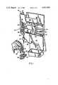
- FIG. 1is a perspective view of metering apparatus used in performing the method described herein, showing the dispenser and the carriage for the dispenser;
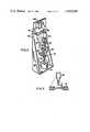
- FIG. 2is a perspective view of a pump for the dispenser and a drive mechanism for the carriage;
- FIG. 3is an enlarged fragmentary elevational view, in section, showing a metering tip in the metering position over an analysis slide;
- FIG. 4ais an enlarged fragmentary elevational view, in section, showing the metering tip and fluid contained therein as it approaches an analysis slide;
- FIG. 4bis a view similar to FIG. 4a, but with the metering tip in the metering position and showing the fluid protruding from the tip;
- FIG. 4cis a view similar to FIG. 4a and FIG. 4b, but showing the flow of the fluid after it contacts the analysis slide;
- FIG. 4dis a view similar to FIG. 4a, but showing the position of the fluid within the metering tip after the reversal of the metering pump;
- FIG. 5ais a graph illustrating the pressure profile of the fluid within the metering tip during one mode of operation.
- FIG. 5bis a graph similar to FIG. 5a, but showing the pressure profile of the fluid within a metering tip during performance of the method of metering disclosed herein.
- the inventionis described hereinafter in connection with performing quantitative chemical analyses of biological fluids, such as blood serum.
- biological fluidssuch as blood serum.
- the inventionis not so limited, and it can also be employed in other applications where precise metering is required.
- dispensing of blood serais described hereinafter by way of example, the invention may be used in dispensing other fluids.
- test elementfor use with the subject invention is disclosed in the commonly-owned U.S. Patent to Pryzbylowicz et al., U.S. Pat. No. 3,992,158, granted on Nov. 16, 1976.
- the test element disclosed in this patentis formed as a multi-layer element containing the necessary reagents for reaction with components of a biological fluid, such as blood serum, deposited thereon.
- Certain reactionscolorimetrically produce a change in optical density in the element which is sensed by a reflectometer, the amount of light reflected from the element varying in accordance with the reaction and being indicative of the amount of a particular analyte present in the fluid.
- test elementfor use with the disclosed invention is shown in the patent to Hamblen et al., U.S. Pat. No. 4,053,381, granted Oct. 11, 1977.
- This patentdescribes a test element, or analysis slide, of the type which is used to potentiometrically designate the activity of ions in a liquid test solution by the use of electrodes.
- Pre-spotrefers to a condition in which a quantity of sample fluid from a metering tip is deposited on an analysis slide, prior to a normal metering cycle, as a result of fluid protruding from the tip during positioning of the tip in the metering position.
- the sera to be dispensedare to be tested by devices requiring very accurate, small volumes of sera.
- the volumes to be dispensedare substantially fixed for a particular application and range from 1 to about 30 microliters, and preferably between about 8 and about 13 microliters.
- Such small volumespermit the performance of multiple tests on a relatively small volume of serum from a patient; in the case of elderly or infant patients, only small volume of blood are available for testing, and the smaller the volume needed for each test, the greater the number of tests which can be run on a given sample of serum.
- metering apparatus 18which is adapted to aspirate sample fluid from a cup 19 supported in a sample tray 20 and to deposit a predetermined amount of the fluid onto an analysis slide 15 supported in a slide distributor 30.
- Metering apparatus 18is adapted to be used in an analyzer, as disclosed, for example, in the aforesaid European Patent Application No. 81400940.3.
- the analysis slide 15is deposited in an incubator (not shown); after an appropriate period of incubation, the slide 15 is read by an analysis means (not shown) adapted to measure a change in the slide as a result of the fluid deposited thereon.
- Metering apparatus 18comprises a dispenser 40, and a means for positioning dispenser 40 which includes a carriage 42 for moving dispenser 40 laterally through a plurality of stations and a vertical drive 44 for raising and lowering dispenser 40 at each of the stations.
- Dispenser 40comprises a dispenser head 46 which is adapted to receive a disposable metering tip 48, and is connected by means of a line 50 to a pump 52 (FIG. 2) of the positive displacement type.
- Pump 52comprises a piston, not shown, which is driven by a bidirectional stepper motor 54.
- motor 54When motor 54 is actuated in one direction, a partial vacuum is created in line 50 by pump 52, and fluid is drawn into tip 48 until the tip is partially filled. Motor 54 is actuated in an opposite direction to meter fluid from tip 48. In the metering operation, motor 54 drives pump 52 for a preselected period during which the pressure in line 50 and tip 48 is raised sufficiently to force about 10 ⁇ l of fluid onto an analysis slide. Under certain operating conditions, depending on the amount of fluid aspirated into tip 48, it may be desirable to vent line 50 before dispensing fluid onto an analysis slide.
- a pressure transducer 56closely monitors pressure in line 50 for purposes which will be explained in more detail hereinafter.
- Sample tray 20is adapted to carry a disposable tip 48 for each of the sample fluids to be analyzed.
- a new tip 48is used with each sample fluid to avoid any cross-contamination problems.
- the cups 19 containing sample fluidare arranged around the outer periphery of tray 20, as shown in FIG. 1.
- An indexing mechanismnot shown, advances tray 20 at the start of each metering cycle to bring a cup 19 and new tip 48 respectively into the aspiration station and the-tip supply station for cooperation with metering apparatus 18.
- Tips 48can be formed by known molding techniques from polymers, such as acetal and polypropylene.
- One tip which is particularly suitable for use in apparatus 18is the tip described and claimed in commonly-owned U.S. Application Ser. No. 168,789, filed on July 14, 1980, by R. L.
- Carriage 42is mounted for horizontal movement on two parallel support rods 70.
- Rods 70are carried on a pylon 43 attached to the analyzer frame, not shown.
- a drive means for carriage 42includes a bidirectional stepper motor 72 (FIG. 2) which is connected to a capstan drive 74.
- Drive 74comprises a drum 76; a cable 78 carried on drum 76 is supported on guide pulleys 80 and connected to carriage 42. It will be seen from FIGS. 1 and 2, that when motor 72 is driven, for example, in a counterclockwise direction, as viewed in FIG. 2, carriage 42 will move to the right (FIG. 1).
- Carriage 42must be located along a line at four points which include the tip supply station, the aspiration station, the metering station and the tip-eject station.
- Four horizontal-position sensors 86 of a photoelectric typecooperate with a flag 87 on carriage 42 to precisely position the carriage 42 at each of these stations.
- Vertical drive 44comprises a rack 90 which is attached to dispenser head 46.
- Rack 90is raised and lowered by means of a pinion 92 driven by a stepper motor 94 mounted on carriage 42.
- Four vertical-position sensors 96cooperate with a flag 98 on rack 90 to precisely determine the vertical position of dispenser head 46.
- Power from a power supply, not shown,is supplied to the sensors 96 and motor 94 through a ribbon cable 100.
- dispenser 40is moved through at least one complete metering cycle for each sample fluid processed.
- carriage 42is moved to the tip-eject station to position dispenser 40 over a waste receptacle 110 where a metering tip 48 from a previous metering cycle is ejected into the receptacle 110 by an ejector, not shown, on head 46.
- Carriage 42is then moved by motor 72 to the tip-supply station where dispenser 40 is located directly over a disposable tip 48 in sample tray 20.
- Dispenser 40is then lowered to pick up a tip 48, raised, and moved laterally to the aspiration station.
- dispenser 40is lowered to locate a tip 48 in a sample cup 19 where it aspirates sufficient sample fluid to perform the number of tests desired. After aspiration and before withdrawal of the tip 48, approximately 10 ⁇ l of fluid are dispensed back into cup 19; this primes the dispenser and insures that the first analysis slide 15 will receive a precise amount of fluid.
- the dispenser 40is then raised, moved laterally to the metering station where tip 48 is positioned directly over an analysis slide 15; tip 48 is then lowered into a guide 116 (FIG. 1) on distributor 30 which locates the tip 48 in the metering position. When the tip 48 is in the metering position, pump 52 is actuated to increase the pressure in the tip sufficiently above ambient to force about 10 ⁇ l of fluid from the tip.
- Apparatus 18is operable in one mode in which pump 52 is driven in a first direction to aspirate fluid into tip 48, stopped while tip 48 is moved into the metering position, and driven in an opposite direction to meter fluid from tip 48; the pressure profile of fluid in tip 48 during such a mode of operation is as shown in FIG. 5a.
- apparatus 18is operated in a different mode in performing the steps of the invention described herein; operation in this different mode results in a pressure profile as shown in FIG. 5b.
- Dispenser 40must be rapidly moved through the metering cycle when apparatus 18 is used in a high-throughput analyzer (not shown). For example, when tip 48 is being lowered into the metering position, the tip 48 is moving at a rate between about 1.5 inches per second and about 6 inches per second. When a tip 48 containing fluid is rapidly moved toward an analysis slide and then stopped abruptly in guide 116, fluid in tip 48 tends to protrude from tip 48 for a brief period of time before being drawn back into the tube by the surface tension and capillary attraction on the fluid. The action of the fluid in tip 48 during positioning of tip 48, in the absence of any means to control the fluid, is shown in FIGS. 4a-4c. In FIG.
- tip 48is shown as it approaches a slide 15; the fluid has a meniscus 120. Just after tip 48 is seated in guide 116 on distributor 30, the meniscus 120 assumes the shape shown in FIG. 4b due to the inertial effect on the fluid. If the fluid contacts slide 15, it tends to spread out, as shown at 122 in FIG. 4c, prior to being severed from the main body of fluid in tip 48. When the fluid contacts slide 15, a certain quantity of fluid remains on the slide which results in a pre-spot.
- motor 54is actuated to drive pump 42 in a reverse direction as tip 48 approaches the metering position; this creates a partial vacuum in line 50 and causes the fluid to be drawn up into tip 48, as shown in FIG. 4d.
- the pressure profile of the fluid in the metering tip when a partial vacuum is drawn during positioning of the tipis as shown in FIG. 5b.
- a partial vacuum of approximately 0.4 inches of water (cross-hatched portion of FIG. 5b)is created in the fluid in tip 48 by driving motor 54 for about 8 steps in the direction to reverse pump 52.
- the partial vacuumis created on the fluid in tip 48 just prior to the point at which tip 48 seats in guide 116 in the metering position, for example 1/4 to 1/2 inch above the metering position.
- the motor 54is actuated to start the metering operation.
- tip 48When tip 48 is in the metering position, pump 52 is actuated for a preselected period to meter the desired amount of sample fluid onto the analysis slide 15. With reference to the pressure profile shown in FIG. 5b, the metering of fluid starts from a point designated "a" and continues for about 400 milliseconds. Tip 48 remains in the metering position for a predetermined time after pump 52 stops to complete the metering operation; then dispenser 40 is raised to a "home" position, shown in FIG. 1. In most cases, more than one analysis will be performed per sample fluid. If additional analyses are being performed, the dispenser 40 will be raised and lowered for each new slide 15. Each time the tip is lowered into the metering position a partial vacuum is drawn to avoid the pre-spot condition.
- Metering apparatus 18is particularly suitable for use with biological fluids, e.g. blood serum having a surface tension which varies between about 28 dynes/cm and about 75 dynes/cm and a relative viscosity between about 0.8 and about 3 (compared to distilled water).
- Apparatus 18is adapted to dispense these fluids such that the mean metered volume does not vary more than 5% from a selected value, and the precision, expressed as a coefficient of variation, is less than 5%.
- metering apparatus 18preferably has the properties listed below.
- the spacing ⁇ of tip 48 from slide 15is preferably between about 0.012 inches (0.030 cm) and about 0.060 inches (0.15 cm).
- the dispense rate at which fluid is expelled from tip 48is between about 10 ⁇ l/sec and about 300 ⁇ l/sec. If the dispense rate is too slow, there is danger of separation of the fluid stream, even with proper spacing of tip 48 from slide 15; if the rate is too fast, fluid tends to build up around tip 48.
- a representative rate within this rangeis 50 ⁇ l/sec, which can be used regardless of the type or chemistry of the slide onto which the fluid is being metered. That is, this fixed, predetermined rate has been used both on colorimetric type slides, e.g. glucose, BUN, or a like assay, as well as on potentiometric slides, e.g. a NA + assay.
- tip 48dwell in the metering position (FIG. 3) between about 0.05 sec and about 0.5 second before being withdrawn. This insures that there will be a clean break of the stream of fluid upon withdrawal; if the tip 48 dwells for a greater period of time, fluid may be pulled out of tip 48 by the slide.
- tip 48be withdrawn from the metering position at a rate of between about 0.2 inches/sec (0.5 cm/sec) and about 2 inches/sec (5.08 cm/sec). The tip 48 is withdrawn at a relatively slow rate to allow a "fluid wipe-off" effect.
- metering apparatus 18In the use of the disclosed metering apparatus with a high-throughput analyzer (not shown) a metering operation takes place approximately every 12 seconds. Thus, it will be seen that each of the steps in the metering cycle must be carefully controlled and monitored, and metering apparatus 18 must function in timed relation to the other elements of the analyzer. Pressure transducer 56 is used to monitor the performance of apparatus 18. Pressure is sensed in line 50, and if conditions are present such as a plugged tip 48, no fluid in cup 19, or a separation of the fluid stream between the tip 48 and the slide 15, they will be detected by the transducer.
- a control system (not shown) for metering apparatus 18could include one or more computers which may take any of the various forms known in the art that include programmable microcomputers. The instructions and method of programming such computers is well known in the art, and thus, no further explanation is considered necessary.
Landscapes
- Physics & Mathematics (AREA)
- Health & Medical Sciences (AREA)
- Life Sciences & Earth Sciences (AREA)
- Chemical & Material Sciences (AREA)
- Analytical Chemistry (AREA)
- Biochemistry (AREA)
- General Health & Medical Sciences (AREA)
- General Physics & Mathematics (AREA)
- Immunology (AREA)
- Pathology (AREA)
- Automatic Analysis And Handling Materials Therefor (AREA)
Abstract
Description
Claims (10)
Priority Applications (1)
| Application Number | Priority Date | Filing Date | Title |
|---|---|---|---|
| US06/387,125US4452899A (en) | 1982-06-10 | 1982-06-10 | Method for metering biological fluids |
Applications Claiming Priority (1)
| Application Number | Priority Date | Filing Date | Title |
|---|---|---|---|
| US06/387,125US4452899A (en) | 1982-06-10 | 1982-06-10 | Method for metering biological fluids |
Publications (1)
| Publication Number | Publication Date |
|---|---|
| US4452899Atrue US4452899A (en) | 1984-06-05 |
Family
ID=23528567
Family Applications (1)
| Application Number | Title | Priority Date | Filing Date |
|---|---|---|---|
| US06/387,125Expired - LifetimeUS4452899A (en) | 1982-06-10 | 1982-06-10 | Method for metering biological fluids |
Country Status (1)
| Country | Link |
|---|---|
| US (1) | US4452899A (en) |
Cited By (47)
| Publication number | Priority date | Publication date | Assignee | Title |
|---|---|---|---|---|
| US4642220A (en)* | 1981-04-10 | 1987-02-10 | Pharmacia Ab | Apparatus for carrying out analysis |
| US4675301A (en)* | 1985-04-01 | 1987-06-23 | Eastman Kodak Company | Method for correcting for changes in air pressure above a liquid to be dispensed from a container mounted on a probe |
| USD297366S (en) | 1986-01-21 | 1988-08-23 | Smithkline Diagnostics, Inc. | Body fluid specimen holder |
| WO1989007980A1 (en)* | 1988-02-29 | 1989-09-08 | Pharmacia-Eni Diagnostics, Inc. | Automatic reagent dispenser |
| US4928540A (en)* | 1988-01-18 | 1990-05-29 | Fuji Photo Film, Co., Ltd. | Method of dispensing coagulative test liquid |
| US5008082A (en)* | 1988-08-25 | 1991-04-16 | Eastman Kodak Company | Analyzers using linear sample trays with random access |
| US5010930A (en)* | 1989-12-22 | 1991-04-30 | Eastman Kodak Company | Pipette and liquid transfer apparatus for dispensing liquid for analysis |
| US5049359A (en)* | 1985-02-28 | 1991-09-17 | Konishiroku Photo Industry Co., Ltd. | Apparatus for biochemical analysis |
| US5055263A (en)* | 1988-01-14 | 1991-10-08 | Cyberlab, Inc. | Automated pipetting system |
| US5075079A (en)* | 1990-05-21 | 1991-12-24 | Technicon Instruments Corporation | Slide analysis system |
| US5085832A (en)* | 1990-07-20 | 1992-02-04 | Eastman Kodak Company | Dispensing mechanism |
| US5089229A (en)* | 1989-11-22 | 1992-02-18 | Vettest S.A. | Chemical analyzer |
| US5141871A (en)* | 1990-05-10 | 1992-08-25 | Pb Diagnostic Systems, Inc. | Fluid dispensing system with optical locator |
| US5240679A (en)* | 1990-10-02 | 1993-08-31 | Hoffmann-La Roche Inc. | Automatic apparatus for inserting pipetting insert into stopper of a sample vessel |
| US5250262A (en)* | 1989-11-22 | 1993-10-05 | Vettest S.A. | Chemical analyzer |
| US5334353A (en)* | 1993-02-03 | 1994-08-02 | Blattner Frederick R | Micropipette device |
| US5463895A (en)* | 1990-11-09 | 1995-11-07 | Abbott Laboratories | Sample pipetting method |
| US5525515A (en)* | 1993-02-03 | 1996-06-11 | Blattner; Frederick R. | Process of handling liquids in an automated liquid handling apparatus |
| EP0741297A1 (en)* | 1995-05-01 | 1996-11-06 | JOHNSON & JOHNSON CLINICAL DIAGNOSTICS, INC. | Method for avoiding volume reduction of first drop |
| US5601980A (en)* | 1994-09-23 | 1997-02-11 | Hewlett-Packard Company | Manufacturing method and apparatus for biological probe arrays using vision-assisted micropipetting |
| US5607861A (en)* | 1994-04-15 | 1997-03-04 | Fuji Photo Film Co., Ltd. | Method for spotting liquid samples onto frameless dry-type chemical analysis film pieces |
| US5639665A (en)* | 1994-12-20 | 1997-06-17 | Fuji Photo Film Co., Ltd. | Method of spotting sample liquid on dry chemical analysis film |
| US5723795A (en)* | 1995-12-14 | 1998-03-03 | Abbott Laboratories | Fluid handler and method of handling a fluid |
| US5811306A (en)* | 1995-09-04 | 1998-09-22 | Fuji Photo Film Co., Ltd. | Liquid spotting method |
| US5915282A (en)* | 1995-12-14 | 1999-06-22 | Abbott Laboratories | Fluid handler and method of handling a fluid |
| US5965828A (en)* | 1995-12-14 | 1999-10-12 | Abbott Laboratories | Fluid handler and method of handling a fluid |
| US6269846B1 (en) | 1998-01-13 | 2001-08-07 | Genetic Microsystems, Inc. | Depositing fluid specimens on substrates, resulting ordered arrays, techniques for deposition of arrays |
| US6293750B1 (en) | 1998-07-14 | 2001-09-25 | Bayer Corporation | Robotics for transporting containers and objects within an automated analytical instrument and service tool for servicing robotics |
| US6407858B1 (en) | 1998-05-14 | 2002-06-18 | Genetic Microsystems, Inc | Focusing of microscopes and reading of microarrays |
| US6428752B1 (en) | 1998-05-14 | 2002-08-06 | Affymetrix, Inc. | Cleaning deposit devices that form microarrays and the like |
| US20030003025A1 (en)* | 2001-06-19 | 2003-01-02 | Macaulay Calum E. | Microvolume liquid dispenser suitable for microarrays and methods related thereto |
| US20030022380A1 (en)* | 2001-07-20 | 2003-01-30 | Ortho-Clinical | Chemistry system for a clinical analyzer |
| US6709872B1 (en)* | 2000-05-02 | 2004-03-23 | Irm Llc | Method and apparatus for dispensing low nanoliter volumes of liquid while minimizing waste |
| US6722395B2 (en) | 1998-01-13 | 2004-04-20 | James W. Overbeck | Depositing fluid specimens on substrates, resulting ordered arrays, techniques for analysis of deposited arrays |
| US20040219074A1 (en)* | 2003-04-30 | 2004-11-04 | Childers Winthrop D. | Test tray and test system for determining response of a biological sample |
| US20050036911A1 (en)* | 2003-08-12 | 2005-02-17 | Sellers James M. | Slide cartridge and reagent test slides for use with a chemical analyzer, and chemical analyzer for same |
| US20050285049A1 (en)* | 1998-03-20 | 2005-12-29 | Montagu Jean I | Focusing of microscopes and reading of microarrays |
| US20070116608A1 (en)* | 2005-11-23 | 2007-05-24 | Birdsell Michael P | Vented ceramic tip arrangement for use with a microarray |
| US7396512B2 (en) | 2003-11-04 | 2008-07-08 | Drummond Scientific Company | Automatic precision non-contact open-loop fluid dispensing |
| WO2008140742A1 (en)* | 2007-05-08 | 2008-11-20 | Idexx Laboratories, Inc. | Chemical analyzer |
| US20100323372A1 (en)* | 2004-07-23 | 2010-12-23 | Fulton Scott P | Immunoassay assembly and methods of use |
| US20110073613A1 (en)* | 2009-09-28 | 2011-03-31 | Beebe W Scott | Fluid dispensing system |
| US8585989B2 (en) | 2003-12-04 | 2013-11-19 | Idexx Laboratories, Inc. | Retaining clip for reagent test slides |
| US9797916B2 (en) | 2014-01-10 | 2017-10-24 | Idexx Laboratories, Inc. | Chemical analyzer |
| WO2020088476A1 (en)* | 2018-10-31 | 2020-05-07 | 江苏卓微生物科技有限公司 | Multi-orifice sample introduction device and multi-orifice sample introduction method |
| US20210239727A1 (en)* | 2018-06-21 | 2021-08-05 | Hitachi High-Tech Corporation | Automatic analyzer |
| US11977091B2 (en) | 2020-07-10 | 2024-05-07 | Idexx Laboratories Inc. | Point-of-care medical diagnostic analyzer and devices, systems, and methods for medical diagnostic analysis of samples |
Citations (4)
| Publication number | Priority date | Publication date | Assignee | Title |
|---|---|---|---|---|
| US3484024A (en)* | 1968-09-06 | 1969-12-16 | American Hospital Supply Corp | Diluter with drop retractor |
| US4000974A (en)* | 1974-09-09 | 1977-01-04 | Beckman Instruments, Inc. | Sample residue cleaning system for biological analyzers |
| US4340390A (en)* | 1980-06-16 | 1982-07-20 | Eastman Kodak Company | Method and apparatus for metering biological fluids |
| US4347875A (en)* | 1980-07-14 | 1982-09-07 | Eastman Kodak Company | Self-cleaning nozzle construction for aspirators |
- 1982
- 1982-06-10USUS06/387,125patent/US4452899A/ennot_activeExpired - Lifetime
Patent Citations (4)
| Publication number | Priority date | Publication date | Assignee | Title |
|---|---|---|---|---|
| US3484024A (en)* | 1968-09-06 | 1969-12-16 | American Hospital Supply Corp | Diluter with drop retractor |
| US4000974A (en)* | 1974-09-09 | 1977-01-04 | Beckman Instruments, Inc. | Sample residue cleaning system for biological analyzers |
| US4340390A (en)* | 1980-06-16 | 1982-07-20 | Eastman Kodak Company | Method and apparatus for metering biological fluids |
| US4347875A (en)* | 1980-07-14 | 1982-09-07 | Eastman Kodak Company | Self-cleaning nozzle construction for aspirators |
Cited By (70)
| Publication number | Priority date | Publication date | Assignee | Title |
|---|---|---|---|---|
| US4642220A (en)* | 1981-04-10 | 1987-02-10 | Pharmacia Ab | Apparatus for carrying out analysis |
| US5049359A (en)* | 1985-02-28 | 1991-09-17 | Konishiroku Photo Industry Co., Ltd. | Apparatus for biochemical analysis |
| US4675301A (en)* | 1985-04-01 | 1987-06-23 | Eastman Kodak Company | Method for correcting for changes in air pressure above a liquid to be dispensed from a container mounted on a probe |
| EP0199466A3 (en)* | 1985-04-01 | 1987-08-19 | Eastman Kodak Company | Dispensing method for improved uniformity in dispensing |
| USD297366S (en) | 1986-01-21 | 1988-08-23 | Smithkline Diagnostics, Inc. | Body fluid specimen holder |
| US5055263A (en)* | 1988-01-14 | 1991-10-08 | Cyberlab, Inc. | Automated pipetting system |
| US4928540A (en)* | 1988-01-18 | 1990-05-29 | Fuji Photo Film, Co., Ltd. | Method of dispensing coagulative test liquid |
| US4927765A (en)* | 1988-02-29 | 1990-05-22 | Pharmacia Eni Diagnostics, Inc. | Automatic reagent dispenser |
| WO1989007980A1 (en)* | 1988-02-29 | 1989-09-08 | Pharmacia-Eni Diagnostics, Inc. | Automatic reagent dispenser |
| US5008082A (en)* | 1988-08-25 | 1991-04-16 | Eastman Kodak Company | Analyzers using linear sample trays with random access |
| US5089229A (en)* | 1989-11-22 | 1992-02-18 | Vettest S.A. | Chemical analyzer |
| US5250262A (en)* | 1989-11-22 | 1993-10-05 | Vettest S.A. | Chemical analyzer |
| US5336467A (en)* | 1989-11-22 | 1994-08-09 | Vettest S.A. | Chemical analyzer |
| US5010930A (en)* | 1989-12-22 | 1991-04-30 | Eastman Kodak Company | Pipette and liquid transfer apparatus for dispensing liquid for analysis |
| EP0434149A3 (en)* | 1989-12-22 | 1991-10-09 | Eastman Kodak Company | Liquid transfer apparatus |
| US5141871A (en)* | 1990-05-10 | 1992-08-25 | Pb Diagnostic Systems, Inc. | Fluid dispensing system with optical locator |
| US5075079A (en)* | 1990-05-21 | 1991-12-24 | Technicon Instruments Corporation | Slide analysis system |
| US5085832A (en)* | 1990-07-20 | 1992-02-04 | Eastman Kodak Company | Dispensing mechanism |
| US5240679A (en)* | 1990-10-02 | 1993-08-31 | Hoffmann-La Roche Inc. | Automatic apparatus for inserting pipetting insert into stopper of a sample vessel |
| US5463895A (en)* | 1990-11-09 | 1995-11-07 | Abbott Laboratories | Sample pipetting method |
| US5334353A (en)* | 1993-02-03 | 1994-08-02 | Blattner Frederick R | Micropipette device |
| US5525515A (en)* | 1993-02-03 | 1996-06-11 | Blattner; Frederick R. | Process of handling liquids in an automated liquid handling apparatus |
| US5607861A (en)* | 1994-04-15 | 1997-03-04 | Fuji Photo Film Co., Ltd. | Method for spotting liquid samples onto frameless dry-type chemical analysis film pieces |
| US5601980A (en)* | 1994-09-23 | 1997-02-11 | Hewlett-Packard Company | Manufacturing method and apparatus for biological probe arrays using vision-assisted micropipetting |
| US5639665A (en)* | 1994-12-20 | 1997-06-17 | Fuji Photo Film Co., Ltd. | Method of spotting sample liquid on dry chemical analysis film |
| EP0741297A1 (en)* | 1995-05-01 | 1996-11-06 | JOHNSON & JOHNSON CLINICAL DIAGNOSTICS, INC. | Method for avoiding volume reduction of first drop |
| US5879944A (en)* | 1995-09-04 | 1999-03-09 | Fuji Photo Film Co., Ltd. | Liquid spotting method and liquid spotting device |
| US5811306A (en)* | 1995-09-04 | 1998-09-22 | Fuji Photo Film Co., Ltd. | Liquid spotting method |
| US5915282A (en)* | 1995-12-14 | 1999-06-22 | Abbott Laboratories | Fluid handler and method of handling a fluid |
| US5723795A (en)* | 1995-12-14 | 1998-03-03 | Abbott Laboratories | Fluid handler and method of handling a fluid |
| US5965828A (en)* | 1995-12-14 | 1999-10-12 | Abbott Laboratories | Fluid handler and method of handling a fluid |
| US6269846B1 (en) | 1998-01-13 | 2001-08-07 | Genetic Microsystems, Inc. | Depositing fluid specimens on substrates, resulting ordered arrays, techniques for deposition of arrays |
| US6722395B2 (en) | 1998-01-13 | 2004-04-20 | James W. Overbeck | Depositing fluid specimens on substrates, resulting ordered arrays, techniques for analysis of deposited arrays |
| US20050244302A1 (en)* | 1998-01-13 | 2005-11-03 | Overbeck James W | Depositing fluid specimens on substrates, resulting ordered arrays, techniques for analysis of deposited arrays |
| US7095032B2 (en) | 1998-03-20 | 2006-08-22 | Montagu Jean I | Focusing of microscopes and reading of microarrays |
| US20050285049A1 (en)* | 1998-03-20 | 2005-12-29 | Montagu Jean I | Focusing of microscopes and reading of microarrays |
| US6407858B1 (en) | 1998-05-14 | 2002-06-18 | Genetic Microsystems, Inc | Focusing of microscopes and reading of microarrays |
| US6428752B1 (en) | 1998-05-14 | 2002-08-06 | Affymetrix, Inc. | Cleaning deposit devices that form microarrays and the like |
| US6332636B1 (en) | 1998-07-14 | 2001-12-25 | Bayer Corporation | Robotics for transporting containers and objects within an automated analytical instrument and service tool for servicing robotics |
| US6374982B1 (en) | 1998-07-14 | 2002-04-23 | Bayer Corporation | Robotics for transporting containers and objects within an automated analytical instrument and service tool for servicing robotics |
| US6293750B1 (en) | 1998-07-14 | 2001-09-25 | Bayer Corporation | Robotics for transporting containers and objects within an automated analytical instrument and service tool for servicing robotics |
| US6638770B1 (en) | 2000-02-09 | 2003-10-28 | Affymetrix, Inc. | Cleaning deposit devices that generate microarrays |
| US6709872B1 (en)* | 2000-05-02 | 2004-03-23 | Irm Llc | Method and apparatus for dispensing low nanoliter volumes of liquid while minimizing waste |
| US20070240527A1 (en)* | 2001-06-19 | 2007-10-18 | Macaulay Calum E | Cytology microarray maker and methods related thereto |
| US20030003025A1 (en)* | 2001-06-19 | 2003-01-02 | Macaulay Calum E. | Microvolume liquid dispenser suitable for microarrays and methods related thereto |
| US7250303B2 (en)* | 2001-07-20 | 2007-07-31 | Ortho-Clinical Diagnostics, Inc. | Chemistry system for a clinical analyzer |
| US20030022380A1 (en)* | 2001-07-20 | 2003-01-30 | Ortho-Clinical | Chemistry system for a clinical analyzer |
| US20040219074A1 (en)* | 2003-04-30 | 2004-11-04 | Childers Winthrop D. | Test tray and test system for determining response of a biological sample |
| US7517494B2 (en) | 2003-04-30 | 2009-04-14 | Hewlett-Packard Development Company, L.P. | Test tray and test system for determining response of a biological sample |
| US20050036911A1 (en)* | 2003-08-12 | 2005-02-17 | Sellers James M. | Slide cartridge and reagent test slides for use with a chemical analyzer, and chemical analyzer for same |
| US7273591B2 (en) | 2003-08-12 | 2007-09-25 | Idexx Laboratories, Inc. | Slide cartridge and reagent test slides for use with a chemical analyzer, and chemical analyzer for same |
| US20070297946A1 (en)* | 2003-08-12 | 2007-12-27 | Sellers James M | Slide cartridge and reagent test slides for use with a chemical analyzer, and chemical analyzer for same |
| US8287823B2 (en) | 2003-08-12 | 2012-10-16 | Idexx Laboratories, Inc. | Slide cartridge and reagent test slides for use with a chemical analyzer, and chemical analyzer for same |
| US7396512B2 (en) | 2003-11-04 | 2008-07-08 | Drummond Scientific Company | Automatic precision non-contact open-loop fluid dispensing |
| US8585989B2 (en) | 2003-12-04 | 2013-11-19 | Idexx Laboratories, Inc. | Retaining clip for reagent test slides |
| US20100323372A1 (en)* | 2004-07-23 | 2010-12-23 | Fulton Scott P | Immunoassay assembly and methods of use |
| US8802026B2 (en)* | 2004-07-23 | 2014-08-12 | Agilent Technologies, Inc. | Immunoassay assembly and methods of use |
| US20070116608A1 (en)* | 2005-11-23 | 2007-05-24 | Birdsell Michael P | Vented ceramic tip arrangement for use with a microarray |
| US9116129B2 (en) | 2007-05-08 | 2015-08-25 | Idexx Laboratories, Inc. | Chemical analyzer |
| US9823109B2 (en) | 2007-05-08 | 2017-11-21 | Idexx Laboratories, Inc. | Chemical analyzer |
| US20100254854A1 (en)* | 2007-05-08 | 2010-10-07 | Idexx Laboratories, Inc. | Chemical analyzer |
| WO2008140742A1 (en)* | 2007-05-08 | 2008-11-20 | Idexx Laboratories, Inc. | Chemical analyzer |
| US8256645B2 (en)* | 2009-09-28 | 2012-09-04 | Fishman Corporation | Fluid dispensing system |
| TWI477324B (en)* | 2009-09-28 | 2015-03-21 | Fishman Corp | Fluid dispensing system |
| US20110073613A1 (en)* | 2009-09-28 | 2011-03-31 | Beebe W Scott | Fluid dispensing system |
| US9797916B2 (en) | 2014-01-10 | 2017-10-24 | Idexx Laboratories, Inc. | Chemical analyzer |
| US20210239727A1 (en)* | 2018-06-21 | 2021-08-05 | Hitachi High-Tech Corporation | Automatic analyzer |
| US12044692B2 (en)* | 2018-06-21 | 2024-07-23 | Hitachi High-Tech Corporation | Automatic analyzer |
| WO2020088476A1 (en)* | 2018-10-31 | 2020-05-07 | 江苏卓微生物科技有限公司 | Multi-orifice sample introduction device and multi-orifice sample introduction method |
| US11977091B2 (en) | 2020-07-10 | 2024-05-07 | Idexx Laboratories Inc. | Point-of-care medical diagnostic analyzer and devices, systems, and methods for medical diagnostic analysis of samples |
Similar Documents
| Publication | Publication Date | Title |
|---|---|---|
| US4452899A (en) | Method for metering biological fluids | |
| US4340390A (en) | Method and apparatus for metering biological fluids | |
| EP0042337B1 (en) | Method and apparatus for metering biological fluids | |
| JP3688723B2 (en) | Dispensing method for various biological fluids | |
| CA1217790A (en) | Method and apparatus for storing and dispensing analysis slides | |
| EP0246632B1 (en) | Pipetting device having an automatic mechanism for replacing nozzle tips | |
| US5030418A (en) | Biochemical analysis apparatus | |
| US5488874A (en) | Liquid aspirating method | |
| JP5686744B2 (en) | Automatic analyzer | |
| EP0438136A2 (en) | Automated dispensing and diluting system | |
| CA1107985A (en) | Automatic tip wiper for a sample aspirating and dispensing tube | |
| US4272482A (en) | Metering apparatus | |
| JP3674503B2 (en) | Automatic analyzer and liquid level detection method of automatic analyzer | |
| EP0500506A1 (en) | Immunoassay apparatus | |
| US5264182A (en) | Sample and reagent delivery device with a probe and probe supporting member for preventing contamination | |
| JPH01141357A (en) | Sample partial injection method for automatic analyzing device | |
| US4928540A (en) | Method of dispensing coagulative test liquid | |
| JP3670503B2 (en) | Dispensing device | |
| US7439076B1 (en) | Liquid dispensing method and device | |
| JPH06230014A (en) | Automatic analysis device | |
| JPH07333230A (en) | Liquid dispensing device and automatic analyzer using the same | |
| JPH06289032A (en) | Dispensing method and dispensing system for automatic analyzer | |
| EP0588236B1 (en) | Liquid dispensing apparatus | |
| JP2776893B2 (en) | Automatic analyzer | |
| JPH06288916A (en) | Biochemically analyzing method |
Legal Events
| Date | Code | Title | Description |
|---|---|---|---|
| AS | Assignment | Owner name:EASTMAN KODAK COMPANY, ROCHESTER, NY A CORP OF NJ Free format text:ASSIGNMENT OF ASSIGNORS INTEREST.;ASSIGNOR:ALSTON, WILTON D.;REEL/FRAME:004235/0942 Effective date:19820608 | |
| STCF | Information on status: patent grant | Free format text:PATENTED CASE | |
| FEPP | Fee payment procedure | Free format text:PAYOR NUMBER ASSIGNED (ORIGINAL EVENT CODE: ASPN); ENTITY STATUS OF PATENT OWNER: LARGE ENTITY | |
| FPAY | Fee payment | Year of fee payment:4 | |
| FPAY | Fee payment | Year of fee payment:8 | |
| FEPP | Fee payment procedure | Free format text:PAYOR NUMBER ASSIGNED (ORIGINAL EVENT CODE: ASPN); ENTITY STATUS OF PATENT OWNER: LARGE ENTITY Free format text:PAYER NUMBER DE-ASSIGNED (ORIGINAL EVENT CODE: RMPN); ENTITY STATUS OF PATENT OWNER: LARGE ENTITY | |
| AS | Assignment | Owner name:CLINICAL DIAGNOSTIC SYSTEMS INC., NEW YORK Free format text:ASSIGNMENT OF ASSIGNORS INTEREST;ASSIGNOR:EASTMAN KODAK COMPANY;REEL/FRAME:007453/0348 Effective date:19950118 | |
| FPAY | Fee payment | Year of fee payment:12 |