US4450481A - Tamper-resistant, expandable communications system - Google Patents
Tamper-resistant, expandable communications systemDownload PDFInfo
- Publication number
- US4450481A US4450481AUS06/296,171US29617181AUS4450481AUS 4450481 AUS4450481 AUS 4450481AUS 29617181 AUS29617181 AUS 29617181AUS 4450481 AUS4450481 AUS 4450481A
- Authority
- US
- United States
- Prior art keywords
- transponder
- remote interrogator
- subscriber
- channel
- control
- Prior art date
- Legal status (The legal status is an assumption and is not a legal conclusion. Google has not performed a legal analysis and makes no representation as to the accuracy of the status listed.)
- Expired - Lifetime
Links
Images


Classifications
- H—ELECTRICITY
- H04—ELECTRIC COMMUNICATION TECHNIQUE
- H04N—PICTORIAL COMMUNICATION, e.g. TELEVISION
- H04N7/00—Television systems
- H04N7/16—Analogue secrecy systems; Analogue subscription systems
- H04N7/173—Analogue secrecy systems; Analogue subscription systems with two-way working, e.g. subscriber sending a programme selection signal
- G—PHYSICS
- G06—COMPUTING OR CALCULATING; COUNTING
- G06Q—INFORMATION AND COMMUNICATION TECHNOLOGY [ICT] SPECIALLY ADAPTED FOR ADMINISTRATIVE, COMMERCIAL, FINANCIAL, MANAGERIAL OR SUPERVISORY PURPOSES; SYSTEMS OR METHODS SPECIALLY ADAPTED FOR ADMINISTRATIVE, COMMERCIAL, FINANCIAL, MANAGERIAL OR SUPERVISORY PURPOSES, NOT OTHERWISE PROVIDED FOR
- G06Q50/00—Information and communication technology [ICT] specially adapted for implementation of business processes of specific business sectors, e.g. utilities or tourism
- G06Q50/06—Energy or water supply
- H—ELECTRICITY
- H04—ELECTRIC COMMUNICATION TECHNIQUE
- H04N—PICTORIAL COMMUNICATION, e.g. TELEVISION
- H04N7/00—Television systems
- H04N7/16—Analogue secrecy systems; Analogue subscription systems
- H04N7/173—Analogue secrecy systems; Analogue subscription systems with two-way working, e.g. subscriber sending a programme selection signal
- H04N7/17345—Control of the passage of the selected programme
- H04N7/17354—Control of the passage of the selected programme in an intermediate station common to a plurality of user terminals
- H—ELECTRICITY
- H04—ELECTRIC COMMUNICATION TECHNIQUE
- H04N—PICTORIAL COMMUNICATION, e.g. TELEVISION
- H04N7/00—Television systems
- H04N7/16—Analogue secrecy systems; Analogue subscription systems
- H04N7/173—Analogue secrecy systems; Analogue subscription systems with two-way working, e.g. subscriber sending a programme selection signal
- H04N2007/17372—Analogue secrecy systems; Analogue subscription systems with two-way working, e.g. subscriber sending a programme selection signal the upstream transmission being initiated or timed by a signal from upstream of the user terminal
Definitions
- This inventionrelates to expandable, multipurpose digital and analog communication systems capable of providing a broad range of communication services to cable system users.
- Such cable systemsembrace community antenna television (CATV) and closed circuit television (CCTV) networks as well as industrial, commericial and institutional broadband cable systems.
- CATVcommunity antenna television
- CCTVclosed circuit television
- the system stationmay be vulnerable to unauthorized tampering. Resistance against tampering is an especially desirable objective when the services to be provided by a CATV system include security functions or payment per TV channel or payment per individual program viewed by the CATV subscriber. To some extent the possibility of such tampering may be deterred by locating the system station outside of the customer's premises--as for example on a utility pole or within an underground cable vault. However, any such location of the system station would necessitate that a separate set of wires be provided between each port and the specific communications service at the customer's premises.
- Sophisticated CATV distribution networkssuch as that described in the aforementioned "Expandable Communications System” include a headend control computer that may be programmed to conduct various diagnostic and maintenance checks which ascertain the status and operating parameters of the system stations. Occasionally, however, the nature of a specific trouble condition--such as intrusive noise in the upstream control signal communications channel--is such that the entire system control is affected. When such disruption occurs it is necessary to systematically isolate segments of the trunk cable and perhaps segments of the tributary distribution branches as well in order to locate the source of the intrusive signal(s).
- the foregoing and other objects and features of my inventionare achieved in one illustrative embodiment in which the "system station" of my prior patent has been reconfigured into two main components.
- the first component of my new combinationis called the remote interrogator unit and is always mounted in a secure location outside the customer's premises; for example on the utility pole, cable strand, or within a pedestal or an underground CATV cable vault.
- the remote interrogator unitwill contain the authorizations for the various services and will periodically poll the second component of my combination which is called the expansion transponder module.
- the expansion module for controlling "premium TV" servicewill also always be located securely but other transponder modules can be located on the customer's premises to interface any other of the specific service features desired by the customer.
- the securely located transponder modulepermits any associated subscriber drop to have duration-controllable access to other channels.
- periodic polling of the transponder module by the remote interrogator unitassures sufficient integrity of the system to permit such functions as meter-reading to be performed with confidence.
- the remote interrogator unituses a main communications channel, exchanges control and information signal communications with a central control computer located at the "headend" of the CATV system, either in the manner described in the aforementioned "Expandable Communications System", or, preferably, in a serial synchronous protocol in order to reduce signaling overhead where this may be important.
- these control and information signal communicationsare carried in radio frequency channels which are passed by the CATV system components. Any of a wide variety of modulation techniques may be employed to impress the information on a radio frequency channel however, frequency shift or phase shift keying are preferred choices.
- the remote interrogator unituses a sub-communication channel, also exchanges control and information signal communications with as many as several thousand expansion transponder modules over the subscriber drop cables or over parts of the CATV trunk and distribution system as required.
- the mode of control signal communication between the remote interrogator unit and the plurality of expansion modules which it servesis by serial, binary, asynchronous transmission over a radio frequency channel which is passed by the intervening system components.
- frequency shift keyingis the preferred choice on the subcommunication channel.
- Both signal communication channels described aboveare operated under a polled protocol.
- the order of addressing unitsis dynamically assigned to optimize service and response parameters for each service in the presence of all other services. For example, when monitoring security alarm zones a period of ten seconds between consecutive polls of any given location is quite acceptable while services such as utility meter reading are required to interrogate the meters much less frequently.
- These functionsare normally conducted sequentially and therefore proceed at a relatively high rate due to the small amount of data required to be exchanged at each location. If, while performing these operations, a subscriber to an alphanumeric information service becomes active, the system gives priority to the requirement for more data and polls that subscriber as frequently as required to transmit the longer messages. As additional subscribers become active the slowdown in the routine polling increases.
- the headend or remote interrogator unit computerinvokes an algorithm which distributes the excess delay among all users, or at the system operator's choice, an algorithm which maintains the maximum acceptable delay for the basic services and allows increased delay on lower priority services.
- the signal communications channels utilized by this inventionare distinct from channels that may be assigned to the television or other transmissions carried by the CATV system cable.
- an entertainment CATV systemutilizes the frequency band from 50 to 300 or more megahertz in the downstream direction (from the headend to the subscriber) and 5 to 30 megahertz in the upstream direction (from the subscriber to the headend).
- the radio frequencies utilized by the signal communication channelsmay be assigned at the convenience of the cable system operator anywhere within the transmission spectra of the cable system.
- a data channel carrier frequency in the vicinity of 120 megahertz downstream and of approximately 7 megahertz upstreamare suggested for communications between the headend and remote interrogator units.
- Signal communications between the headend and the remote interrogator unitswill normally utilize data rates in the range of 200,000 to 1,500,000 bits per second and occupy a bandwidth of 1 to 8 megahertz in each direction.
- Signal communications between the remote interrogator unit and the transponder moduleswill normally utilize data rates of a few kilobits per second, except as detailed below.
- the frequencies of the carriers employed for communications to transponder modulesare advantageously chosen to be immediately below the CATV upstream channels, for example the carrier from remote interrogator to transponder module may be set at 4.5 megahertz while 5.0 megahertz may be used from transponder module to interrogator.
- the signal communications protocolestablishes overall control by the central control computer and control of the transponder modules by the respective remote interrogator units.
- handshakingoccurs to verify proper system operation and data may be passed along with the handshaking messages.
- broadcast messagesare transmitted to all units or to groups of units determined by their assigned addresses or to groups dynamically assembled through use of special instruction messages.
- the transponder modules for these interface functionsare advantageously located on the trunk and distribution cableways themselves rather than on the premises of any particular subscriber.
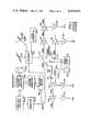
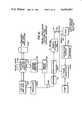
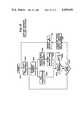
- FIGS. 1 and 2 arranged as shown in FIG. 3is a block diagram layout of a typical CATV system showing the location of the remote interrogator units and expansion transponder modules of my invention;
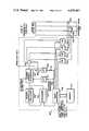
- FIG. 4is the schematic diagram of one type of remote interrogator unit of my invention which is capable of directly serving subscriber drops and any expansion modules connected to such subscriber drops;
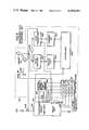
- FIG. 5is a schematic diagram of another type of remote interrogator unit of my invention for serving expansion modules located on subscriber drops or in circuit with a main branch of the CATV cable itself;
- FIG. 6is a schematic diagram of a typical expansion transponder module
- FIG. 7is a schematic diagram of the premium TV controller of my invention for use in the remote interrogator unit of FIG. 4;
- FIG. 8is a schematic diagram of the premium TV controller for use in a transponder module which is controlled by the remote interrogator of FIG. 5;
- FIG. 9is a schematic diagram of a subscriber telephone set served by the transponder module of FIG. 6;
- FIG. 10is a schematic diagram of a digital, video, audio system for interactive access of catalog type data bases containing digital, video and audio information such as is required for interactive catalog shopping;
- FIG. 11is a flow chart of the steps involved in polling of remote interrogator units by the headend;
- FIG. 12is a diagram of the message format used in FIG. 11;
- FIG. 13is a flow chart of the steps involved in the polling of the expansion modules in a group served by a typical remote interrogator unit.
- FIG. 14is a diagram of the message format used in FIG. 13.
- FIG. 1illustrates the headend 101 and principal trunk cables 108 of a typical star or tree CATV cable network.
- a plurality of different types of remote interrogator units 117 of FIG. 1 and 215 and 216 of FIG. 2 together with a plurality of different types of expansion transponder modules 119, 125, 218, 219 and 224 of my inventionare shown occupying typical positions in the network. All branches of the cable system emanate from headend 101 where both off-air signals collected from antennae 102 and satellite receiving equipment 103 may be combined with locally originated programming signals 104 to make up the entertainment product to be transmitted via the cable to the CATV subscriber drops 220.
- the signals transmittedare divided by power divider 107 to be transmitted along the several trunk cables 108a,b,c,d,e,f and g.
- Signal losses in the trunk cablesare made up by amplifiers 109. These amplifiers normally contain equalizers to compensate for the difference in cable loss relative to frequency.
- the trunk system, made up of trunk cables 108 and amplifiers 109carries the signal geographically to the various areas to be served.
- the signals delivered to subscribers' premisesare generally not derived directly from the trunk system, rather the trunk system is tapped at the amplifiers 109 by the use of bridger amplifiers 110a through 110d to feed the distribution cables 211a through 211d. Losses in distribution cables 211a through 211d are compensated by distribution amplifiers 212a through 211d (FIG. 2) which also contain equalizers. In both trunk and distribution sections of the CATV system the active components are usually powered via the coaxial cable by power supplies 121 connected by power inserters 122 (FIG. 1).
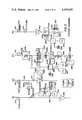
- Distribution cable 211a(FIG. 2) is tapped to feed subscriber drop cables 220 by means of directional couplers or taps 213.
- Taps 213are usually grouped in units of 2, 4, or 8 and are therefore sometimes known as multitaps.
- a typical subscriber drop 220supplies television signals to a customer's premises where it may feed one or more TV sets 214.
- all transmission componentsincluding power dividers 107, trunk cable 108, trunk amplifiers 109, bridger amplifiers 110 and power inserters 122 of FIG. 1 as well as distribution cable 211, distribution amplifiers 212 and multitaps 213 of FIG. 2 are each made capable of bi-directional transmission.
- central control computer 105which advantageously may comprise an Xycom 180 series computer or a Digital Equipment Corporation PDP-11 series computer, communicates with the remote interrogator unit 117 of FIG. 1, and with the remote interrogator units 215 and 216 of FIG. 2, through master modem 106.
- Remote interrogator units 117, 215 and 216communicate bilaterally, not only with central control computer 105 at the headend 101, but each also communicates according to a polled protocol with a respective plurality of expansion transponder modules.
- Remote interrogator unit 117controls expansion transponder module 119 of FIG. 1 and modules 218a, 218b and 219a of distribution cables 211a and 211b of FIG. 2.
- Remote interrogator unit 216a in distribution cable 211ccontrols premium TV transponder module 224 and expansion transponder module 218c.
- Remote interrogator unit 216balso in distribution cable 211c, controls expansion transponder modules 219b and 218d.
- unit 215acontrols module 218e.
- the expansion transponder modulesmay be situated along the trunk, distribution and drop cables.
- module 119is situated in trunk cable 108c to control trunk cables 108a, 108b and 211a and 211b of the CATV network itself utilizing switches internal to trunk amplifiers 109.
- Modules 218, 219, and 224are situated to interface with the various customer services such as security, utility meter reading, videotex terminals, CATV system components and the like.
- transponder modulesAs transponder modules are installed in the system, the locations and respective address are stored by headend computer 105. Disconnection or failure of any transponder unit is indicated by its failure to answer when polled. In addition, tamper indication may be provided by tamper sensors within or attached to any transponder unit and connected to status input(s) discussed later.
- Remote interrogator units 215a and 215bare type I units and are shown in distribution branch 211d directly feeding one to several customer drops 220, eight being a typical number.
- Remote interrogator units 216a and 216b in cable branch 211care type II units.
- a type II unitis usually located at the output of either a trunk amplifier 109, a bridger amplifier 110 or a distribution amplifier 212 and serves an area of a CATV system which may extend as far as the next amplifier or other device containing a filter which blocks a part of the remote interrogator/transponder communications.
- Remote interrogator unit 117 in FIG. 1is a type III unit and is located strategically in trunk cable 108c to control entire segments 108a, 108b and 108c of trunk cable 108.
- the type III unitmay also similarly be employed in the distribution system to control the switching in and out of a distribution cable.
- Highpass and bandstop filtersmay be utilized to suppress spurious signals that may enter the system from the subscriber drops.
- bandstop filter 222a located at multitap 213is tuned to block the frequencies of 5-30 megahertz so as to suppress spurious signals arising at the drops 220 served by multitap 213 from intruding upon the 5-30 megahertz band used for upstream communications to the headend.
- a bandstop filter 222bmay also be employed within a type I remote interrogator unit 215a such as is shown in cable branch 211d and a bandstop filter 227 is advantageously employed in conjunction with premium TV control transponder module 224 in cable branch 211c to prevent intrusive signals in the upstream frequency spectrum, which may be originated or picked up on the subscriber drops 220, from propagating on the CATV trunk and distribution system thereby disrupting upstream communications.
- the employment of such filtersis of extreme importance in controlling ingress of such spurious signals, the exact source of which would be difficult to pinpoint from the headend.
- FIG. 4illustrates a typical type I remote interrogator unit such as that located in distribution cable 211d.
- the type I unithas the ability to directly serve a plurality of subscriber drops 220.
- the CATV signals on distribution cable 211dare passed on downstream through directional coupler 402 on conductor 401.
- Coupler 402also divides the signals into tributary branches 402a and 402b.
- Bidirectional branch 402aserves receiver/transmitter 405.
- Branch 402bis a downstream-only branch and serves the plurality of different subscriber drops 220 via highpass filter 222b, power divider 403, radio frequency switches 410 and the straight-thru paths of directional couplers 409 and 423.
- the status of switches 410 and the signal conveyed over the angled paths of directional couplers 409 and 423are determined by microprocessor 406.
- Microprocessor 406is programmed to interpret the message structure of the communications received over tributary branch 402a from headend 101 as well as to format reply messages to the headend using the transmitter portion of communications receiver/transmitter 205.
- Microprocessor 406controls the sub-communications system on subscriber drops 220, interchanging data with transponder module 218e through subcom transmitter/receiver 408 via directional couplers 409.
- microprocessor 406controls radio frequency switches 410 via bus 410a in order to provide a respective disconnect function for each of subscriber drops 220. This feature allows selective disconnection of the television signals while still providing continuous subcom communications over all of drops 220 utilizing the subcom transmitter/receiver 408 and the directional couplers 409.
- the communications portion of the remote interrogator units and transponder modulesbe powered from the CATV cable so that power will be available whenever the cable system is operational regardless of failure of other power sources.
- the source of power for the power supply 412which also feeds other sections of the electronics in the remote interrogator units.
- the type I remote interrogator unit of FIG. 4receives command messages and information from the headend central contol computer 105, FIG. 1.
- the messagesare demodulated in the receiver portion of the communications transmitter/receiver 405 and are passed to microprocessor 406 and to premium TV control 422, the operation of which is described in detail hereinafter.
- the messages received by the microprocessor 406are interpreted, any necessary information or message content is stored in memory 407 and any necessary acknowledgement message is composed and furnished to the transmitter portion of the communications transmitter/receiver 405 for transmission to the headend.
- microprocessor 406may also prepare and transmit appropriate messages to transponder module 218e over one of subscriber drops 220 using a handshaking interchange in the sub-communication system similar to that employed in the main communication system with the headend. Except for the premium TV controller 422 and the manner in which the microprocessor 406 controls communications with the remote expansion transponder module 218e both of which will hereinafter be described in detail, the type I remote interrogator unit is very similar to the "system station" of the above-mentioned copending application.
- FIG. 5illustrates the type II and type III remote interrogator units which are utilized in locations remote from the subscriber drops 220 which they serve.
- Type II and type III unitsdiffer from each other only in parameter values assigned to the circuit elements.
- Type II unitsmay be located at the outputs of trunk amplifiers 109, bridger amplifiers 110 or distribution amplifiers 212 and serve the same transponder modules as are fed by the associated amplifier so that there are no active components (amplifiers) between the type II remote interrogator unit and the transponder modules with which it communicates. Communications to and from the transponder modules may therefore be assigned at any frequency within the overall passband of the intervening passive components of the cable system. Frequencies usually selected lie in the vicinity of 3 to 5 megahertz which are readily passed by the passive components but do not occupy frequency assignments in the normal upstream spectrum (5.75 to 29.75 megahertz).
- a type III remote interrogator unit 117serves some transponder modules, such as 218a, 218b and 219a of FIG. 2 which are beyond one or more amplifiers from the remote interrogator unit.
- Such intervening amplifier(s)contain highpass filters in the downstream direction and lowpass filters in the upstream direction requiring a choice of communication frequencies which will propagate through the amplifier passbands.
- Remote interrogator units types II and IIIinclude a bandstop filter 223 which separates its upsteam terminal "a" and downstream terminal “b” connections to the cable 108 or 211.
- communications transmitter/receiver 505sends to and receives from headend 101 via directional coupler 501 in similar fashion to communications transmitter/receiver 405 of FIG. 4.
- subcom transmitter 508exchanges signals with the remotely located expansion transponder modules 218a, 218b, 218c, 219a or 224 (see FIG. 2) via directional coupler 502.
- Bandstop filter 223is tuned to the frequencies utilized for transmission between transponder modules and remote interrogator units (4.5 to 5.0 megahertz in the previous example) and prevents transmission of these subcom frequencies between sections of the cable system controlled by other remote intergator units. If such mixing of subcom signals were allowed, disruption of subcom communications would result. Bandstop filter 223 does not impede signal transmission between any remote interrogator units (which operate a 7 megahertz in the example) and the headend 101.
- directional coupler 502is located as 502a.
- Directional couplers 502 and 502acan also be used simultaneously to communicate with transponder modules in both the upstream and downstream directions.
- Bandstop filters 228a and 228b shown in cable 211cmaintain separation of subcom signals where remote interrogator unit 216b controls upstream transponder module 219b as well as downstream transponder module 218d. In such case bandstop filter 223 is unnecessary.
- FIG. 6illustrates a typical transponder expansion module.
- This moduleis configured both for comparatively low data rate utility meter reading and security input/output as well as for high data rate videotex services.
- the modulemay be controlled by any type of remote interrogator unit 117, 215 or 216 via directional coupler 213 and subscriber drop cable 220.
- Subcom transmitter/receiver 604 of the transponder modulecommunicates with the subcom transmitter/receiver 508 of the remote interrogator unit.
- Microprocessor 605compares the preset address furnished by circuit 606 with the addresses of messages received by transmitter/receiver 604 and processes the approriately addressed messages according to the algorithms supplied in the RAM/ROM memory 613.
- microprocessor 605In normal operation the task of microprocessor 605 is to relay input information from the input ports 607 to the associated type I, II or III remote interrogator unit and to provide appropriate command information to output ports 608.
- Transponder module 218is illustrated having eight input ports 607 and eight output ports 608.
- the input ports 607are used to monitor security zones and other binary status functions and the output ports 608, as instructed by the remote interrogator unit, are for various command functions including actuation of devices for load shedding and security deterents.
- the programming of the microprocessor 605provides for reading of utility meters 225, FIG. 2.
- Utility meter readingis normally implemented by one of the outputs 608 providing an interrogating signal to the meter and by a correspoding one of the inputs 607 accepting the meter readout.
- the interrogating signalmay be a constant input voltage, a clock signal or some form of coded activation signal.
- the meter readout signal delivered to inputs 607is generally a serial data stream.
- the programming of microprocessor 605allows one such transponder with eight input ports 607 and eight output ports 608 to read up to eight meters or monitor eight status functions or a combination thereof.
- Power for the transponder modulemay advantageously be taken from drop cable 220 through isolating filter 609 to energize power supply 610.
- Power supply 610supplies power to transponder transmitter/receiver 604, microprocessor 605, program ROM 613, address circuitry 606 and serial input/output port 611.
- Data signals received by transmitter/receiver 604 and which exhibit a data rate higher than that which can be continuously processed by microprocessor 605are delivered to serial input/output port 611.
- Videotex servicefor example, is a service requiring a data rate that may be higher than the normal data rate in order to supply information without undue delay.
- the associated remote interrogator unitaddresses transponder module 218 at the normal data rate and issues the special command which instructs microprocessor 605, through connection 614, to establish the bypass condition and activate the input/output port 611.
- the normal modeis reestablished by another special command transmitted at the normal data rate which microprocessor 605 interprets to deactivate serial input/output port 611 via connection 614.
- a "device ready” signalis introduced via connection 615 from the external device and used to enable port 611. Since transponder module 218 has various functions which cannot always be executed simultaneously it can only receive data from port 611 at certain times. This readiness to receive data is indicated by asserting the "transponder ready" signal via connection 616. Services connected to serial port 611 are generally powered externally and not by power supply 610 within the module.
- FIG. 11is a flow chart showing the operations performed at the headend control computer 105 in order to provide demand polling of remote interrogtor units in the main communications channel.
- the first RIU addressis set 1102 and that RIU is polled 1103.
- the polled RIUanswers with its status and data 1104.
- These simultaneous functionsare checked for completion 1105 and a wait 1106 is imposed until both are finished. If additional information 1107 is to be sent to the current RIU a check is made 1108 to see if the fixed time increment allotted to each RIU transmission has expired. If time is still available a block of data of predetermined length is sent 1109, and another check for data 1107 is made as the process continues.
- a check to determine if the last RIU has been polled 1111is made. If negative, the RIU address is incremented 1112 and the process continues. Where more data is present 1107 but the time has expired 1108, a flag is set 1110 to indicate that more data is still to be sent to the RIU addressed. At this point the process re-enters with the check for last RIU 1111.
- the flag 1110In a heavily loaded system the flag 1110 would typically be set for numerous RIUs during one cycle of polls. When the last RIU has been polled 1111 a check is made to see if a flag(s) is set 1113. If no flag is set the system idles until the predetermined cycle or frame period has expired 1114 and resets the RIU address to the first RIU 1115 and starts the next poll cycle. It should be noted that the waiting step 1114 could be eliminated and, on a lightly loaded system, the cycle time would be shortened and each RIU polled more often than under the fixed cycle length procedure.
- the first RIU address with a flagis set 1116 and polled 1117 and one block of data is sent 1118. If still more data exists for this RIU 1119 and the frame time has not expired 1120 an additional block of data is sent 1118, etc. When all of the data for this RIU is exhausted 1119, end of frame is checked 1121. If time remains the process is re-entered by checking for other data flags 1113. If end of frame is indicated in either 1120 or 1121 the RIU address is reset 1115 and the next polling cycle (frame) is started. Any unsent data is retained in memory and is first to be sent in subsequent polling cycles.
- FIG. 12illustrates a typical main communications channel message format which is used both to and from the remote interrogator units.
- the flag words 1201 and 1209are used to define and separate messages.
- Address bytes 1202 and 1203address the proper remote interrogrator units. Two bytes are shown which is typical and will address 65,536 units in an eight-bit byte protocol.
- the control byte 1204indicates the type of message such as a message to an individual RIU, a group address, an all call message, etc.
- Command byte 1205signals appropriate actions by the unit(s) addressed such as suppress response, send certain data block, send status info, etc. If the message applies to a certain transponder only, byte 1206 indicates the transponder address.
- Data bytes 1207are used as required and could be numerous (hundreds or even thousands) in services such as videotex.
- Bytes 1208are for error checking (and in some cases correcting) and are shown as cyclic redundancy check which is a standard protocol.
- the synchronous protocol employedis very efficient (few overhead bytes) when long messages (many data bytes) are employed.
- FIG. 13is a flow chart of the demand polling sequence of the subcom system. This is much the same as the maincom system except that each transponder advantageously operates in a half duplex mode as herein after decribed.
- the first transponder addressis set and the unit is polled 1302.
- the transponderdoes not answer immediately.
- the transponder addressis incremented 1303 and the next transponder is polled 1304.
- the previous transpondersends its status including operational indicators and priority information such as security zone status. Included in the operational status is the number of data bytes ready for transfer. This information is received by the RIU 1305 and the status information is stored 1306 for later transmission to the headend computer.
- FIG. 14illustrates a typical subcom message format. The downstream message from the RIU to the transponders starts in the status phase, with an address N 1401.
- transponder N-1transmits its status 1402 which is usually the status of security zones or other priority information.
- Command byte 1403gives transponder N any necessary commands such as to read a utility meter(s) or shed a load(s).
- the messageis terminated by flag 1405.
- 1405 transponder N-1transmits one byte of data usually an indication of further data to be transferred.
- the cycleis repeated to transponder N+1 1406, 1407 while transponder N responds 1408, 1409. After a complete poll cycle of all transponder units the data phase is entered and all transponders with additional data are sequentially addressed 1410 and told 1411 to send all or part of the waiting data. In addition any down loaded data for the transponder is sent 1412.
- the wait 1413is invoked by the RIU microprocessor if necessary and is calculated to make the received message 1415 no longer than the transmit message 1410, 1411, 1412, 1413 and 1414.
- the transmission endis signaled with flag 1414.
- the processis repeated to transponder address P 1416 (the next transponder with a data requirement) while receiving data from unit M 1417.
- FIG. 7shows the detail of premium TV control 422 of the type I remote interrogator unit of FIG. 4.
- Authorizations for each of the many tiers of premium TV programming that may be selectively purchased by subscribersare stored in the headend computer 105.
- the data for each subscriber regarding those channels that are authorized and not authorizedis downloaded from computer 105 to the receiver portion of communications transmitter/receiver 405 of the appropriate remote interrogator unit (FIG. 4) via the data stream carried by the CATV system.
- the authorization informationis routed to microprocessor 706 of premium TV control 422.
- Microprocessor 706,stores the information in memory 707.
- the functions of microprocessor 706 and memory 707may be performed by microprocessor 406 of FIG. 4 and memory 407.
- Microprocessor 706utilizes the authorization information to selectively control the application of TV jamming signals to the various subscriber drops 220.
- the frequency of the jamming carrier to be generatedis selected so that both the video and audio information of the TV transmission will be disrupted.
- Jamming frequenciesin the range of approximately 100 to 500 kilohertz above and below the video carrier frequency will be most effective. This range of frequencies is close enough to the normal video carrier to preclude the use of a resonant frequency trap by one who might attempt to defeat the effect of the jamming signal. Indeed, in most cases, the video carrier itself would also be affected by the use of such a trap so that the TV picture would nevertheless be destroyed.
- jamming signalBecause of the intercarrier audio demodulation techniques used in TV receivers, such a jamming signal also produces frequency excursions in the FM audio demodulator thereby also disrupting audio reception. In addition the jamming signal is also pulled to effect a high level buzz which destroys the intelligibility of the audio.
- a pulse of radio frequency energyof approximately 500 microseconds duration at a repetition rate of at least 50 pulses per second.
- the maximum number of channels which can be simultaneously jammedis 20.
- at least 16 channelscan be simultaneously jammed with this technique by introducing properly related pulsed frequencies into each channel sequentially so that each channel receives approximately 100 pulses per second within the effective frequency range before mentioned.
- the pulsed signal from the voltage controlled oscillator 702is made simultaneously available to several subscriber drops 220, by power driver 703, each output of which feeds a respective one of drops 220 through through a respective switch 704.
- each of switches 704is individually controlled by microprocessor 706 in synchronism with the stepped frequencies of voltage controlled oscillator 702.
- microprocessor 706opens the associated switch 704 during the time the jamming signal for the desired channel is being applied thereby removing jamming from the desired channel.
- Switch 704remains closed during the period that the jamming signal is applied to the non-authorized channels.
- Each switchis individually synchronized so that any combination of authorized and non-authorized channels may be independently achieved for each drop.
- Authorizationscan be readily changed from the headend 101 to initiate or cancel services.
- AGCautomatic gain control circuit consisting of power divider 703, mixer 708, lowpass filter 709, detector 710, lowpass filter 711 and voltage variable attenuator 712.
- Incoming video carriersare sampled by power divider 403 and mixed with the jamming carrier delivered by attenuator 712 through power divider 703 to mixer 708. Since the jamming carrier is always within 500 kilohertz of the video carrier of the channel to be jammed lowpass filter 709 is designed to pass frequencies of 500 kilohertz and lower (the lower mixer product) to detector 710.
- the voltage developed by detector 710is passed through lowpass filter 711 and compared with d.c. reference voltage 705 to control voltage variable attenuator 712 to adjust the jamming signal to the desired level.
- the voltage from the detector 710is also applied through connection 713 to microprocessor 706 which verifies proper system operation.
- the amplitude of the interfering carrier pulsesshould exceed the amplitude of the video carrier by 5 to 20 dB.
- the effect of this excess levelis to capture the automatic gain control (AGC) of the TV receiver and overload it sufficiently to prevent complete recovery before the arrival of the next consecutive pulse in the channel of interest.
- AGCautomatic gain control
- the apparatus of FIG. 7injects the jamming carrier locally, a signal level well in excess of the TV carrier levels may be employed without disturbing other channels. Injecting signals at such excessive levels at a common location such as the headend 101 for transmission throughout the CATV system would result in unacceptable operation due to overloading of the CATV trunk, bridger and distribution amplifiers 109, 110 and 212.
- Voltage controlled oscillator (VCO) 702generates the desired carrier jamming frequencies in accordance with the appropriate ratios delivered by microprocessor 706 to synthesizer 701. The ratio delivered is that between the desired frequency and the synthesizer's internal reference frequency from reference generator 713. Synthesizer 701 generates a control voltage which establishes the frequency generated by voltage controlled oscillator 702.
- FIG. 8illustrates the details of premium TV control transponder module 224 of FIG. 2 which is used with type II or type III remote interrogator units 117 or 216a.
- Transponder module 224is mounted outside of the subscriber premises on the cable strand, utility pole, pedestal, vault, or other relatively secure location.
- the premium TV control 808 of module 224operates in similar fashion to the premium TV controls depicted in FIGS. 4 and 7.
- Communications between module 224 and its remote interrogator 216aare advantageously carried out at frequencies below 5.75 megahertz but above the frequency (typically 2 to 3 megahertz) at which significant transmission degradation occurs in passive devices such as directional couplers 213 and 801. All signals on the distribution cable 211c (FIG. 2) are passed through module 224 on connection 810.
- Bandstop filter 227isolates subscriber drops 220 from the CATV distribution cable 211c over the frequency range of upstream transmissions (typically 5.75. to 29.75 megahertz) while not affecting transmission of the lower frequency subcom signals.
- Power divider 803distributes the radio frequency signals among subscriber drops 220, subcom transmitter/receiver 805 and premium TV control 808.
- Subcom transmitter/receiver 805processes messages to and from microprocessor 806 which stores the required premium TV service authorizations in memory 807 and commands the action of premium TV control 808 in the manner previously described.
- the properly formatted bursts of interferring carrier signalsare transmitted to the subscriber drops 220 through directional couplers 809.
- Switches 804are controlled by microprocessor 806 in the same manner as switches 410 were controlled by microprocessor 406 to effect a total TV signal remote disconnect function. Switches 804 pass the subcom communication frequencies to allow communications at all times to any additional transponder module such as 218c, FIG. 2, which may be connected to the subscriber drop 220.
- Transponder modules including premium TV control transponder 224may also be used with type III remote interrogator unit by altering the subcommunications channel frequencies into the frequency bands passed by the intervening CATV system amplifiers and passive components (typically 50 to 440 megahertz downstream and 5 to 30 megahertz upstream).
- the type I remote interrogator(FIG. 4), which incorporates premium TV control circuit 422, and the premium TV control transponder module 224 are both highly tamper resistant since, in each case, the equipment containing the authorizatin information as well as the channel control devices is mounted outside the dwelling on the pole, strand or in a secure pedestal and is usually fed by hard cable (solid aluminum outer conductor) and housed in a sealed container.
- the premium TV control systemis highly effective because a high level jamming carrier signal is placed close to the frequency of the video carrier and because the jamming frequency is caused to continually be changed. Since the characteristics of the pulsed signals used to effect the premium TV jamming are software controlled new jamming algorithms may be downloaded from the headend should newer TV sets require different parameters for effective jamming.
- pole mounted converterPrior to my invention one of the most secure means of premium TV program protection was the "pole mounted converter".
- the pole mounted converteris controlled by the subscriber from within the dwelling. Upon request from the subscriber the pole mounted converter selects a single authorized TV channel. This signal then appears as the only signal on the drop cable.
- This systemwhile mechanically tamper resistant, allows only one program to be viewed at a given time even though there may be a plurality of TV sets within the dwelling. In order to serve two TV sets simultaneously with different programs, two drops must be installed, and so on.
- the instant inventionallows as many TV sets on the subscriber premises as desired since all authorized channels and "free" channels are transmitted simultaneously down a single drop cable 220.
- the communication system of my present inventionis extremely versatile allowing for a very broad range of expansion into new services, including the addition of analog functions.
- One such applicationis the provision of telephone service.
- subscriber CATV telephone set 900interfaces with drop cable 220 via coupler 909 and a transponder module 218 which is of the type shown in FIG. 6.
- the transponder module 218includes parallel inputs 607 and outputs 608, as well as a serial input/output port 611.
- the on and off-hook states of switch 914 and dialing signals from keypad 901are detected at inputs 607. More particularly, the signals generated by the four horizontal and four vertical buttons of keypad 901 are sensed by respective ones of input ports 607.
- output ports 608may provide strobes to keypad 901 to sense depressions of keys while others may be employed to actuate indicator lamps 920 and ringer 921, as required.
- a rotary dial(not shown) may also be accomodated by connection to one of input ports 607.
- Talking channelsare established on single sideband suppressed carrier analog channels carried by the CATV cable system.
- Voice transmitter 904 and voice receiver 905are conventional circuits and may conveniently be implemented with integrated circuits.
- the information defining the frequency of the talking channelis downloaded through the cable system to the associated remote interrogator unit and subsequently down the subscriber drop 220 to the subscriber CATV telephone set 900.
- Digital information originated at the headendis passed through the serial output port 611 of the transponder module 218 to the synthesizer circuit 902 to set the frequencies of the voice transmitter 905 and the voice receiver 906. These frequencies may be established conveniently in any desired section of the upstream and downstream spectra of the cable system and need have no special relationship to the data channel frequencies.
- the synthesizer 902controls a first voltage controlled oscillator 903 used for transmission and a second VCO 904 used to select the desired receive signal in the receiver 906.
- Signals from the microphone of handset 911are fed into transmitter 905 where they modulate the carrier provided by transmit VCO 903 and are then fed into power divider 907 which in this instance operates as a power combiner.
- the signal from the power combiner 907is then applied through directional coupler 909 into the CATV system.
- Telephone transmissionsare carried on frequencies which are passed to the remote interrogator unit 117, 215 or 216.
- the signal to be received by the telephone set 900is delivered through the remote interrogator unit 117, 215 or 216, down the subscriber drop cable through the directional coupler 909 and the power divider 907 into the receiver 906.
- the frequency of the receiver VCO 904is set for proper demodulation of the single sideband supressed carrier audio signal.
- the demodulated audio signalproduces the audio output for the handset 911.
- the headend control for the telephone systemis relatively simple in terms of allocation of frequencies. Frequency determination and assignment is accomplished by the headend control computer 105. For a full function telephone system, an additional computer (not shown) may be employed to provide all desired special features associated with modern telephone systems.
- FIG. 10shows the combination digital/video/audio system to provide not only alphanumeric information but also full color video, still pictures.
- the communications control computer 105is augmented with a data base control computer(s) 1001 which has high memory capacity in terms of both internal and external storage 1002.
- This computeralso controls a video disk data base 1003 which contains the required picture content for the services being offered.
- the data base computeris ported to various servers 1010 such as department stores, catalog warehouses, banks, etc.
- the data base computer 1001supplies alphanumeric information upon request, controls the video disk memory 1003 and undertakes the administrative tasks such as accounting and billing.
- the video disk data baseWhen video picture information is required the video disk data base is accessed and the picture outputs sequenced and fed to a video modulator 1004 which modulates the TV pictures on a radio frequency carrier in a standard analog format.
- the output of the modulatorsis combined, by frequency division multiplexing, in the power divider (combiner) 1005 with the output of the master modem 106 for transmission throughout the cable system 1006 via headend 101.
- One standard TV channelcan transmit 30 full resolution, full color still pictures (frames) per second. In many cases single field resolution is adequate. Since there are two fields per TV frame the transmission rate is doubled when only one field is used per picture.
- the digital and video informationalong with the request information (in the opposite direction), are carried on the cable system 1006.
- the appropriate remote interrogator unit 117, 215 or 216receives a digital message with the alphanumeric data and instructions for selection of the proper TV frame or field. This information is relayed to the appropriate transponder module 218 on the subscriber drop 220.
- the transponder module 218communicates with the connected interactive terminal 1007.
- the series of television still picturesis also transmitted through the directional coupler 113, down the drop 220 and through directional coupler 1008 to TV the frame grabber and store 1009.
- the TV frame grabber and store unit 1009selects and stores the proper video picture and makes it available for viewing on the TV set 214.
- audio information to provide music, voice or other soundmay be sent in digitized form and stored in the interactive terminal.
- Audio signalsare combined with the TV picture stored in the frame grabber and store 1009 and modulated by standard techniques for transmission to the TV set 214 where both audio and video are demodulated for customer listening and viewing.
- alphanumeric informationis overlaid on the video pictures for combined viewing effects. This is a practical example of the extent to which the expansion features of the communications system can be carried and is a unique implementation of a highly desirable interactive service providing digital, video and audio information on an individual request basis on a cable system.
Landscapes
- Engineering & Computer Science (AREA)
- Business, Economics & Management (AREA)
- Multimedia (AREA)
- Signal Processing (AREA)
- Health & Medical Sciences (AREA)
- Economics (AREA)
- Marketing (AREA)
- Tourism & Hospitality (AREA)
- General Health & Medical Sciences (AREA)
- Human Resources & Organizations (AREA)
- Public Health (AREA)
- Primary Health Care (AREA)
- Strategic Management (AREA)
- Water Supply & Treatment (AREA)
- Physics & Mathematics (AREA)
- General Business, Economics & Management (AREA)
- General Physics & Mathematics (AREA)
- Theoretical Computer Science (AREA)
- Two-Way Televisions, Distribution Of Moving Picture Or The Like (AREA)
- Small-Scale Networks (AREA)
Abstract
Description
Claims (6)
Priority Applications (1)
| Application Number | Priority Date | Filing Date | Title |
|---|---|---|---|
| US06/296,171US4450481A (en) | 1981-08-25 | 1981-08-25 | Tamper-resistant, expandable communications system |
Applications Claiming Priority (1)
| Application Number | Priority Date | Filing Date | Title |
|---|---|---|---|
| US06/296,171US4450481A (en) | 1981-08-25 | 1981-08-25 | Tamper-resistant, expandable communications system |
Publications (1)
| Publication Number | Publication Date |
|---|---|
| US4450481Atrue US4450481A (en) | 1984-05-22 |
Family
ID=23140908
Family Applications (1)
| Application Number | Title | Priority Date | Filing Date |
|---|---|---|---|
| US06/296,171Expired - LifetimeUS4450481A (en) | 1981-08-25 | 1981-08-25 | Tamper-resistant, expandable communications system |
Country Status (1)
| Country | Link |
|---|---|
| US (1) | US4450481A (en) |
Cited By (94)
| Publication number | Priority date | Publication date | Assignee | Title |
|---|---|---|---|---|
| US4535355A (en)* | 1982-06-23 | 1985-08-13 | Microdesign Limited | Method and apparatus for scrambling and unscrambling data streams using encryption and decryption |
| US4580161A (en)* | 1982-11-22 | 1986-04-01 | Pico Products, Inc. | Cable television subscriber control system including addressable filters having a variable pole |
| US4633309A (en)* | 1985-05-06 | 1986-12-30 | Oak Industries Inc. | Cable television master/slave decoder control |
| US4638356A (en)* | 1985-03-27 | 1987-01-20 | General Instrument Corporation | Apparatus and method for restricting access to a communication network |
| US4673976A (en)* | 1984-05-31 | 1987-06-16 | American Television & Communications Corporation | Cable television system data verification apparatus |
| US4684980A (en)* | 1984-05-31 | 1987-08-04 | American Television & Communications Corporation | System for controlling communications on a cable television network |
| US4710956A (en)* | 1984-05-31 | 1987-12-01 | American Television & Communications Corporation | Cable television system |
| US4734764A (en)* | 1985-04-29 | 1988-03-29 | Cableshare, Inc. | Cable television system selectively distributing pre-recorded video and audio messages |
| US4740835A (en)* | 1982-10-30 | 1988-04-26 | Pioneer Electronic Corporation | Wire-tap preventing apparatus for community antenna television terminals |
| EP0181863A4 (en)* | 1984-05-19 | 1988-05-16 | Am Cable Tv Ind Inc | Tamper-resistant, expandable communications system. |
| US4754426A (en)* | 1984-05-31 | 1988-06-28 | American Television & Communications Corporation | System for controlling communications on a cable television network |
| US4757371A (en)* | 1985-02-22 | 1988-07-12 | Mitsubishi Denki Kabushiki Kaisha | Still picture transmission apparatus |
| US4769838A (en)* | 1984-12-10 | 1988-09-06 | Pioneer Electronic Corporation | Community antenna television reception controlling apparatus |
| US4792849A (en)* | 1987-08-04 | 1988-12-20 | Telaction Corporation | Digital interactive communication system |
| US4792971A (en)* | 1984-05-18 | 1988-12-20 | Pioneer Electronic Corporation | Selective viewing control system for CATV |
| US4792972A (en)* | 1986-08-19 | 1988-12-20 | Scientific-Atlanta, Inc. | Remote programming of CATV channel authorization unit |
| US4802215A (en)* | 1983-07-22 | 1989-01-31 | Independent Broadcasting Authority | Security system for television signal encryption |
| US4810898A (en)* | 1987-07-17 | 1989-03-07 | Am Communications, Inc. | RF network isolation switch |
| US4814972A (en)* | 1983-10-23 | 1989-03-21 | Keycom Electronic Publishing | Method and videotex apparatus for fast access of remotely located information |
| US4829372A (en)* | 1987-08-20 | 1989-05-09 | Telaction Corporation | Presentation player |
| WO1989008966A1 (en)* | 1988-03-10 | 1989-09-21 | Scientific Atlanta, Inc. | Off-premises cable television channel interdiction method and apparatus |
| US4891694A (en)* | 1988-11-21 | 1990-01-02 | Bell Communications Research, Inc. | Fiber optic cable television distribution system |
| US4910791A (en)* | 1985-12-26 | 1990-03-20 | Am Communications, Inc. | Monitoring and control of data communications |
| US4914695A (en)* | 1988-11-03 | 1990-04-03 | General Instrument Corporation | Method and apparatus for frequency control of multiple oscillators using a single frequency-locked-loop |
| US4937865A (en)* | 1988-11-15 | 1990-06-26 | Syrcuits International Inc. | Cable TV channel security system having remotely addressable traps |
| US4941040A (en)* | 1985-04-29 | 1990-07-10 | Cableshare, Inc. | Cable television system selectively distributing pre-recorded video and audio messages |
| US5014125A (en)* | 1989-05-05 | 1991-05-07 | Cableshare, Inc. | Television system for the interactive distribution of selectable video presentations |
| US5014309A (en)* | 1988-03-10 | 1991-05-07 | Scientific-Atlanta, Inc. | Off-premises cable television channel interdiction method and apparatus |
| US5016272A (en)* | 1989-06-16 | 1991-05-14 | Stubbs James R | Home video system |
| US5018186A (en)* | 1988-04-21 | 1991-05-21 | Canon Kabushiki Kaisha | Communicating apparatus providing discriminated voice and/or image communication |
| US5019910A (en)* | 1987-01-29 | 1991-05-28 | Norsat International Inc. | Apparatus for adapting computer for satellite communications |
| WO1991008651A1 (en)* | 1989-12-06 | 1991-06-13 | Scientific-Atlanta, Inc. | Optimum amplitude and frequency of jamming carrier in interdiction program denial system |
| US5027426A (en)* | 1989-07-07 | 1991-06-25 | Chiocca Jr Joseph J | Signal coupling device and system |
| US5058198A (en)* | 1989-03-31 | 1991-10-15 | Am Communications, Inc. | Radio frequency tap unit which can be reconfigured with minimal disruption of service |
| GB2243275A (en)* | 1990-02-21 | 1991-10-23 | Scientific Atlanta | Cable tv system selectively jams programs to subscribers |
| US5113496A (en)* | 1987-08-04 | 1992-05-12 | Mccalley Karl W | Bus interconnection structure with redundancy linking plurality of groups of processors, with servers for each group mounted on chassis |
| US5119188A (en)* | 1988-10-25 | 1992-06-02 | Telaction Corporation | Digital audio-video presentation display system |
| US5140633A (en)* | 1991-03-22 | 1992-08-18 | North American Philips Corporation | Cable subscriber control device using shared jamming modules |
| US5144267A (en)* | 1989-12-06 | 1992-09-01 | Scientific-Atlanta, Inc. | Variable slope network for off-premises CATV system |
| WO1992022987A1 (en)* | 1991-06-13 | 1992-12-23 | Scientific-Atlanta, Inc. | System for broadband descrambling of sync suppressed television signals |
| US5191410A (en)* | 1987-08-04 | 1993-03-02 | Telaction Corporation | Interactive multimedia presentation and communications system |
| US5208854A (en)* | 1988-03-10 | 1993-05-04 | Scientific-Atlanta, Inc. | Picture carrier controlled automatic gain control circuit for cable television interdiction or jamming apparatus |
| US5208665A (en)* | 1987-08-20 | 1993-05-04 | Telaction Corporation | Presentation player for an interactive digital communication system |
| EP0540411A1 (en)* | 1991-10-31 | 1993-05-05 | Telediffusion De France | Interface for connecting a television monitor with a local area home network |
| US5231660A (en)* | 1988-03-10 | 1993-07-27 | Scientific-Atlanta, Inc. | Compensation control for off-premises CATV system |
| US5233652A (en)* | 1991-02-19 | 1993-08-03 | At&T Bell Laboratories | Selective off-premises jamming for premium CATV service |
| US5245420A (en)* | 1990-11-27 | 1993-09-14 | Scientific-Atlanta, Inc. | CATV pay per view interdiction system |
| US5265160A (en)* | 1992-06-10 | 1993-11-23 | Scientific-Atlanta, Inc. | Interdiction method and apparatus with pulsed mode jamming |
| US5278908A (en)* | 1992-06-10 | 1994-01-11 | Scientific-Atlanta, Inc. | Interdiction method and apparatus with programmable jamming effectiveness |
| US5289541A (en)* | 1988-03-10 | 1994-02-22 | Scientific-Atlanta, Inc. | Interdiction method and apparatus with constant blanking and variable dwell times |
| US5303295A (en)* | 1988-03-10 | 1994-04-12 | Scientific-Atlanta, Inc. | Enhanced versatility of a program control by a combination of technologies |
| US5317635A (en)* | 1992-06-10 | 1994-05-31 | Scientific-Atlanta, Inc. | Interdiction method and apparatus with mode control for variable frequency elements |
| US5323462A (en)* | 1988-03-10 | 1994-06-21 | Scientific-Atlanta, Inc. | CATV subscriber disconnect switch |
| US5341424A (en)* | 1992-06-10 | 1994-08-23 | Scientific-Atlanta, Inc. | Interdiction method and apparatus with frequency change inhibit function |
| US5345504A (en)* | 1988-03-10 | 1994-09-06 | Scientific-Atlanta, Inc. | Differential compensation control for off-premises CATV system |
| US5359419A (en)* | 1989-04-10 | 1994-10-25 | Pioneer Electronic Corporation | Programmable CATV system and termainal unit therefor, including acknowledgement of program request |
| US5361301A (en)* | 1992-06-10 | 1994-11-01 | Scientific-Atlanta, Inc. | Interdiction method and apparatus with direct memory control of variable frequency elements |
| US5393513A (en)* | 1986-01-14 | 1995-02-28 | Alliance Pharmaceutical Corp. | Stable, highly concentrated fluoro carbon emulsions |
| US5463689A (en)* | 1988-03-10 | 1995-10-31 | Scientific-Atlanta | Interdiction method and apparatus with random mode jamming |
| US5485630A (en)* | 1994-03-31 | 1996-01-16 | Panasonic Technologies, Inc. | Audio/video distribution system |
| WO1996005700A1 (en)* | 1994-08-11 | 1996-02-22 | Stanford Telecommunications, Inc. | Controller for downloading and playback of information and entertainment |
| US5505901A (en)* | 1988-03-10 | 1996-04-09 | Scientific-Atlanta, Inc. | CATV pay per view interdiction system method and apparatus |
| US5534912A (en)* | 1994-04-26 | 1996-07-09 | Bell Atlantic Network Services, Inc. | Extended range video on demand distribution system |
| US5539449A (en)* | 1993-05-03 | 1996-07-23 | At&T Corp. | Integrated television services system |
| US5539450A (en)* | 1993-04-16 | 1996-07-23 | News Datacom Limited | Methods and systems for providing additional service applications in pay television |
| US5566351A (en)* | 1994-06-20 | 1996-10-15 | International Business Machines Corporation | Adaptive polling system by generating sequence of polling signals whose magnitudes are functionally related to the occurrence of the busy signal |
| US5592212A (en)* | 1993-04-16 | 1997-01-07 | News Datacom Ltd. | Methods and systems for non-program applications for subscriber television |
| US5608662A (en)* | 1995-01-12 | 1997-03-04 | Television Computer, Inc. | Packet filter engine |
| US5621792A (en)* | 1993-07-20 | 1997-04-15 | Telediffusion De France | Method and system of controlling the mode of access to signals, in particular picture signals |
| US5684472A (en)* | 1996-05-08 | 1997-11-04 | Motorola, Inc. | Method and apparatus for remotely accessing meter status information in a meter reading system |
| US5715305A (en)* | 1995-09-21 | 1998-02-03 | At&T Corp. | Apparatus for and method of providing consumers with local access carrier |
| US5761312A (en)* | 1995-06-07 | 1998-06-02 | Zelikovitz, Deceased; Joseph | Enhanced individual intelligent communication platform for subscribers on a telephone system |
| US5790180A (en)* | 1995-12-28 | 1998-08-04 | At&T Corp. | Video telephone call handling system and method |
| US5887243A (en) | 1981-11-03 | 1999-03-23 | Personalized Media Communications, L.L.C. | Signal processing apparatus and methods |
| DE29820900U1 (en) | 1998-11-16 | 1999-04-15 | Klein, Patrick, 85716 Unterschleißheim | Electronic range limiter or range interferer for high-frequency transmissions in broadband transmission networks |
| US5905942A (en)* | 1997-02-18 | 1999-05-18 | Lodgenet Entertainment Corporation | Multiple dwelling unit interactive audio/video distribution system |
| US5966410A (en)* | 1995-01-30 | 1999-10-12 | Motorola, Inc. | Method and system for cleaning a frequency band |
| US20020042923A1 (en)* | 1992-12-09 | 2002-04-11 | Asmussen Michael L. | Video and digital multimedia aggregator content suggestion engine |
| US20020120569A1 (en)* | 1997-10-16 | 2002-08-29 | Day Mark E. | System and method for communication between remote locations |
| US20030028889A1 (en)* | 2001-08-03 | 2003-02-06 | Mccoskey John S. | Video and digital multimedia aggregator |
| US20030028890A1 (en)* | 2001-08-03 | 2003-02-06 | Swart William D. | Video and digital multimedia acquisition and delivery system and method |
| US20030025832A1 (en)* | 2001-08-03 | 2003-02-06 | Swart William D. | Video and digital multimedia aggregator content coding and formatting |
| WO2002049222A3 (en)* | 2000-12-15 | 2003-03-20 | Cic Global Llc | System and method for communication between remote locations |
| US20030169120A1 (en)* | 2002-03-06 | 2003-09-11 | Satoshi Tachi | Modulation circuit for wireless installation |
| US20060170517A1 (en)* | 2005-01-11 | 2006-08-03 | Advantest Corporation | Signal transfer system, signal output circuit board, signal receiving circuit board, signal output method, and signal receiving method |
| US20070199042A1 (en)* | 2005-12-22 | 2007-08-23 | Bce Inc. | Delivering a supplemented CCTV signal to one or more subscribers |
| US20080107274A1 (en)* | 2006-06-21 | 2008-05-08 | Rf Code, Inc. | Location-based security, privacy, assess control and monitoring system |
| US20100015991A1 (en)* | 2008-07-15 | 2010-01-21 | Kota Enterprises, Llc | System and method for calling a geosoc |
| US20100041419A1 (en)* | 2008-08-12 | 2010-02-18 | Kota Enterprises, Llc | Customized content delivery through the use of arbitrary geographic shapes |
| US7769344B1 (en)* | 1981-11-03 | 2010-08-03 | Personalized Media Communications, Llc | Signal processing apparatus and methods |
| US8463931B2 (en) | 2008-12-08 | 2013-06-11 | Lerni Technology, LLC | Protected distribution and location based aggregation service |
| US9078014B2 (en) | 2000-06-19 | 2015-07-07 | Comcast Ip Holdings I, Llc | Method and apparatus for targeting of interactive virtual objects |
| USRE47642E1 (en) | 1981-11-03 | 2019-10-08 | Personalized Media Communications LLC | Signal processing apparatus and methods |
| US20230254060A1 (en)* | 2020-07-02 | 2023-08-10 | Nippon Telegraph And Telephone Corporation | Communication network terminating device, communication system, signal jamming method and signal jamming program |
Citations (10)
| Publication number | Priority date | Publication date | Assignee | Title |
|---|---|---|---|---|
| US3750022A (en)* | 1972-04-26 | 1973-07-31 | Hughes Aircraft Co | System for minimizing upstream noise in a subscriber response cable television system |
| US3786424A (en)* | 1972-02-22 | 1974-01-15 | Coaxial Scient Corp | Communications system for data transmission and retrieval |
| US3806814A (en)* | 1972-04-26 | 1974-04-23 | Hughes Aircraft Co | Phantom subscriber |
| US3889050A (en)* | 1974-04-11 | 1975-06-10 | Gte Sylvania Inc | Subscription television system and switching station therefor |
| US4025851A (en)* | 1975-11-28 | 1977-05-24 | A.C. Nielsen Company | Automatic monitor for programs broadcast |
| US4035838A (en)* | 1975-03-17 | 1977-07-12 | Societa Italiana Telecomunicazioni Siemens S.P.A. | Cable distribution system for wide-band message signals |
| US4343042A (en)* | 1979-07-10 | 1982-08-03 | Cablebus Systems Corporation | Bi-directional data transmission and control system |
| US4345273A (en)* | 1979-11-06 | 1982-08-17 | Siemens Aktiengesellschaft | Broad band switching system |
| US4365267A (en)* | 1980-05-30 | 1982-12-21 | Pioneer Electronic Corporation | Passive data monitor for use with polling pattern generator in CATV system |
| US4367557A (en)* | 1975-08-09 | 1983-01-04 | Stern Joseph L | Wired broadcasting systems |
- 1981
- 1981-08-25USUS06/296,171patent/US4450481A/ennot_activeExpired - Lifetime
Patent Citations (10)
| Publication number | Priority date | Publication date | Assignee | Title |
|---|---|---|---|---|
| US3786424A (en)* | 1972-02-22 | 1974-01-15 | Coaxial Scient Corp | Communications system for data transmission and retrieval |
| US3750022A (en)* | 1972-04-26 | 1973-07-31 | Hughes Aircraft Co | System for minimizing upstream noise in a subscriber response cable television system |
| US3806814A (en)* | 1972-04-26 | 1974-04-23 | Hughes Aircraft Co | Phantom subscriber |
| US3889050A (en)* | 1974-04-11 | 1975-06-10 | Gte Sylvania Inc | Subscription television system and switching station therefor |
| US4035838A (en)* | 1975-03-17 | 1977-07-12 | Societa Italiana Telecomunicazioni Siemens S.P.A. | Cable distribution system for wide-band message signals |
| US4367557A (en)* | 1975-08-09 | 1983-01-04 | Stern Joseph L | Wired broadcasting systems |
| US4025851A (en)* | 1975-11-28 | 1977-05-24 | A.C. Nielsen Company | Automatic monitor for programs broadcast |
| US4343042A (en)* | 1979-07-10 | 1982-08-03 | Cablebus Systems Corporation | Bi-directional data transmission and control system |
| US4345273A (en)* | 1979-11-06 | 1982-08-17 | Siemens Aktiengesellschaft | Broad band switching system |
| US4365267A (en)* | 1980-05-30 | 1982-12-21 | Pioneer Electronic Corporation | Passive data monitor for use with polling pattern generator in CATV system |
Cited By (226)
| Publication number | Priority date | Publication date | Assignee | Title |
|---|---|---|---|---|
| US9043859B1 (en) | 1981-11-02 | 2015-05-26 | Personalized Media Communications, Llc | Signal processing apparatus and methods |
| US8558950B1 (en) | 1981-11-03 | 2013-10-15 | Personalized Media Communications LLC | Signal processing apparatus and methods |
| US8555310B1 (en) | 1981-11-03 | 2013-10-08 | Personalized Media Communications, Llc | Signal processing apparatus and methods |
| US7797717B1 (en) | 1981-11-03 | 2010-09-14 | Personalized Media Communications, Llc | Signal processing apparatus and methods |
| US7805738B1 (en) | 1981-11-03 | 2010-09-28 | Personalized Media Communications, Llc | Signal processing apparatus and methods |
| US7805749B1 (en) | 1981-11-03 | 2010-09-28 | Personalized Media Communications, Llc | Signal processing apparatus and methods |
| US7793332B1 (en) | 1981-11-03 | 2010-09-07 | Personalized Media Communications, Llc | Signal processing apparatus and methods |
| USRE48682E1 (en) | 1981-11-03 | 2021-08-10 | Personalized Media Communications LLC | Providing subscriber specific content in a network |
| US7805748B1 (en) | 1981-11-03 | 2010-09-28 | Personalized Media Communications, Llc | Signal processing apparatus and methods |
| US7783252B1 (en)* | 1981-11-03 | 2010-08-24 | Personalized Media Communications, Llc | Signal processing apparatus and methods |
| US7784082B1 (en) | 1981-11-03 | 2010-08-24 | Personalized Media Communications, Llc | Signal processing apparatus and methods |
| US7801304B1 (en) | 1981-11-03 | 2010-09-21 | Personalized Media Communications, Llc | Signal processing apparatus and methods |
| US7774809B1 (en) | 1981-11-03 | 2010-08-10 | Personalized Media Communications, Llc | Signal processing apparatus and method |
| USRE48633E1 (en)* | 1981-11-03 | 2021-07-06 | Personalized Media Communications LLC | Reprogramming of a programmable device of a specific version |
| US7769344B1 (en)* | 1981-11-03 | 2010-08-03 | Personalized Media Communications, Llc | Signal processing apparatus and methods |
| USRE48565E1 (en) | 1981-11-03 | 2021-05-18 | Personalized Media Communications LLC | Providing a subscriber specific solution in a computer network |
| US7769170B1 (en)* | 1981-11-03 | 2010-08-03 | Personalized Media Communications, Llc | Signal processing apparatus and methods |
| USRE48484E1 (en) | 1981-11-03 | 2021-03-23 | Personalized Media Communications, Llc | Signal processing apparatus and methods |
| US7764685B1 (en) | 1981-11-03 | 2010-07-27 | Personalized Media Communications, L.L.C. | Signal processing apparatus and methods |
| US10715835B1 (en) | 1981-11-03 | 2020-07-14 | John Christopher Harvey | Signal processing apparatus and methods |
| USRE47968E1 (en) | 1981-11-03 | 2020-04-28 | Personalized Media Communications LLC | Signal processing apparatus and methods |
| US10616638B1 (en) | 1981-11-03 | 2020-04-07 | Personalized Media Communications LLC | Signal processing apparatus and methods |
| US10609425B1 (en)* | 1981-11-03 | 2020-03-31 | Personalized Media Communications, L.L.C. | Signal processing apparatus and methods |
| USRE47867E1 (en) | 1981-11-03 | 2020-02-18 | Personalized Media Communications LLC | Signal processing apparatus and methods |
| US10523350B1 (en) | 1981-11-03 | 2019-12-31 | Personalized Media Communications LLC | Signal processing apparatus and methods |
| USRE47642E1 (en) | 1981-11-03 | 2019-10-08 | Personalized Media Communications LLC | Signal processing apparatus and methods |
| US10334292B1 (en) | 1981-11-03 | 2019-06-25 | Personalized Media Communications LLC | Signal processing apparatus and methods |
| US9674560B1 (en) | 1981-11-03 | 2017-06-06 | Personalized Media Communications LLC | Signal processing apparatus and methods |
| US9294205B1 (en) | 1981-11-03 | 2016-03-22 | Personalized Media Communications LLC | Signal processing apparatus and methods |
| US9210370B1 (en) | 1981-11-03 | 2015-12-08 | Personalized Media Communications LLC | Signal processing apparatus and methods |
| US7761890B1 (en) | 1981-11-03 | 2010-07-20 | Personalized Media Communications, Llc | Signal processing apparatus and methods |
| US9038124B1 (en) | 1981-11-03 | 2015-05-19 | Personalized Media Communications, Llc | Signal processing apparatus and methods |
| US8973034B1 (en) | 1981-11-03 | 2015-03-03 | Personalized Media Communications LLC | Signal processing apparatus and methods |
| US8914825B1 (en)* | 1981-11-03 | 2014-12-16 | Personalized Media Communications LLC | Signal processing apparatus and methods |
| US8893177B1 (en)* | 1981-11-03 | 2014-11-18 | {Personalized Media Communications, LLC | Signal processing apparatus and methods |
| US8869228B1 (en) | 1981-11-03 | 2014-10-21 | Personalized Media Communications, Llc | Signal processing apparatus and methods |
| US8869229B1 (en) | 1981-11-03 | 2014-10-21 | Personalized Media Communications, Llc | Signal processing apparatus and methods |
| US8843988B1 (en) | 1981-11-03 | 2014-09-23 | Personalized Media Communications, Llc | Signal processing apparatus and methods |
| US8839293B1 (en) | 1981-11-03 | 2014-09-16 | Personalized Media Communications, Llc | Signal processing apparatus and methods |
| US8804727B1 (en) | 1981-11-03 | 2014-08-12 | Personalized Media Communications, Llc | Signal processing apparatus and methods |
| US8752088B1 (en) | 1981-11-03 | 2014-06-10 | Personalized Media Communications LLC | Signal processing apparatus and methods |
| US8739241B1 (en) | 1981-11-03 | 2014-05-27 | Personalized Media Communications LLC | Signal processing apparatus and methods |
| US8711885B1 (en) | 1981-11-03 | 2014-04-29 | Personalized Media Communications LLC | Signal processing apparatus and methods |
| US8713624B1 (en) | 1981-11-03 | 2014-04-29 | Personalized Media Communications LLC | Signal processing apparatus and methods |
| US8683539B1 (en)* | 1981-11-03 | 2014-03-25 | Personalized Media Communications, Llc | Signal processing apparatus and methods |
| US8675775B1 (en) | 1981-11-03 | 2014-03-18 | Personalized Media Communications, Llc | Signal processing apparatus and methods |
| US8646001B1 (en) | 1981-11-03 | 2014-02-04 | Personalized Media Communications, Llc | Signal processing apparatus and methods |
| US8640184B1 (en) | 1981-11-03 | 2014-01-28 | Personalized Media Communications, Llc | Signal processing apparatus and methods |
| US8635644B1 (en)* | 1981-11-03 | 2014-01-21 | Personalized Media Communications LLC | Signal processing apparatus and methods |
| US8621547B1 (en) | 1981-11-03 | 2013-12-31 | Personalized Media Communications, Llc | Signal processing apparatus and methods |
| US8613034B1 (en) | 1981-11-03 | 2013-12-17 | Personalized Media Communications, Llc | Signal processing apparatus and methods |
| US8607296B1 (en) | 1981-11-03 | 2013-12-10 | Personalized Media Communications LLC | Signal processing apparatus and methods |
| US8601528B1 (en) | 1981-11-03 | 2013-12-03 | Personalized Media Communications, L.L.C. | Signal processing apparatus and methods |
| US8587720B1 (en) | 1981-11-03 | 2013-11-19 | Personalized Media Communications LLC | Signal processing apparatus and methods |
| US8584162B1 (en) | 1981-11-03 | 2013-11-12 | Personalized Media Communications LLC | Signal processing apparatus and methods |
| US8572671B1 (en) | 1981-11-03 | 2013-10-29 | Personalized Media Communications LLC | Signal processing apparatus and methods |
| US8566868B1 (en)* | 1981-11-03 | 2013-10-22 | Personalized Media Communications, L.L.C. | Signal processing apparatus and methods |
| US7752650B1 (en) | 1981-11-03 | 2010-07-06 | Personalized Media Communications, Llc | Signal processing apparatus and methods |
| US8559635B1 (en) | 1981-11-03 | 2013-10-15 | Personalized Media Communications, L.L.C. | Signal processing apparatus and methods |
| US7752649B1 (en) | 1981-11-03 | 2010-07-06 | Personalized Media Communications, Llc | Signal processing apparatus and methods |
| US8395707B1 (en) | 1981-11-03 | 2013-03-12 | Personalized Media Communications LLC | Signal processing apparatus and methods |
| US8191091B1 (en) | 1981-11-03 | 2012-05-29 | Personalized Media Communications, Llc | Signal processing apparatus and methods |
| US8112782B1 (en) | 1981-11-03 | 2012-02-07 | Personalized Media Communications, Llc | Signal processing apparatus and methods |
| US8060903B1 (en) | 1981-11-03 | 2011-11-15 | Personalized Media PMC Communications, L.L.C. | Signal processing apparatus and methods |
| US8046791B1 (en) | 1981-11-03 | 2011-10-25 | Personalized Media Communications, Llc | Signal processing apparatus and methods |
| US7992169B1 (en) | 1981-11-03 | 2011-08-02 | Personalized Media Communications LLC | Signal processing apparatus and methods |
| US7953223B1 (en) | 1981-11-03 | 2011-05-31 | Personalized Media Communications, L.L.C. | Signal processing apparatus and methods |
| US7940931B1 (en) | 1981-11-03 | 2011-05-10 | Personalized Media Communications LLC | Signal processing apparatus and methods |
| US7926084B1 (en) | 1981-11-03 | 2011-04-12 | Personalized Media Communications LLC | Signal processing apparatus and methods |
| US7908638B1 (en) | 1981-11-03 | 2011-03-15 | Personalized Media Communications LLC | Signal processing apparatus and methods |
| US7889865B1 (en) | 1981-11-03 | 2011-02-15 | Personalized Media Communications, L.L.C. | Signal processing apparatus and methods |
| US7870581B1 (en) | 1981-11-03 | 2011-01-11 | Personalized Media Communications, Llc | Signal processing apparatus and methods |
| US7864248B1 (en) | 1981-11-03 | 2011-01-04 | Personalized Media Communications, Llc | Signal processing apparatus and methods |
| US7865920B1 (en) | 1981-11-03 | 2011-01-04 | Personalized Media Communications LLC | Signal processing apparatus and methods |
| US7864956B1 (en) | 1981-11-03 | 2011-01-04 | Personalized Media Communications, Llc | Signal processing apparatus and methods |
| US7861263B1 (en) | 1981-11-03 | 2010-12-28 | Personalized Media Communications, Llc | Signal processing apparatus and methods |
| US7860249B1 (en) | 1981-11-03 | 2010-12-28 | Personalized Media Communications LLC | Signal processing apparatus and methods |
| US7860131B1 (en) | 1981-11-03 | 2010-12-28 | Personalized Media Communications, Llc | Signal processing apparatus and methods |
| US7861278B1 (en) | 1981-11-03 | 2010-12-28 | Personalized Media Communications, Llc | Signal processing apparatus and methods |
| US7856649B1 (en) | 1981-11-03 | 2010-12-21 | Personalized Media Communications, Llc | Signal processing apparatus and methods |
| US7856650B1 (en) | 1981-11-03 | 2010-12-21 | Personalized Media Communications, Llc | Signal processing apparatus and methods |
| US7849479B1 (en) | 1981-11-03 | 2010-12-07 | Personalized Media Communications, Llc | Signal processing apparatus and methods |
| US5887243A (en) | 1981-11-03 | 1999-03-23 | Personalized Media Communications, L.L.C. | Signal processing apparatus and methods |
| US7849480B1 (en) | 1981-11-03 | 2010-12-07 | Personalized Media Communications LLC | Signal processing apparatus and methods |
| US7849493B1 (en) | 1981-11-03 | 2010-12-07 | Personalized Media Communications, Llc | Signal processing apparatus and methods |
| US7844995B1 (en) | 1981-11-03 | 2010-11-30 | Personalized Media Communications, Llc | Signal processing apparatus and methods |
| US7840976B1 (en) | 1981-11-03 | 2010-11-23 | Personalized Media Communications, Llc | Signal processing apparatus and methods |
| US7836480B1 (en) | 1981-11-03 | 2010-11-16 | Personalized Media Communications, Llc | Signal processing apparatus and methods |
| US7830925B1 (en) | 1981-11-03 | 2010-11-09 | Personalized Media Communications, Llc | Signal processing apparatus and methods |
| US7831204B1 (en) | 1981-11-03 | 2010-11-09 | Personalized Media Communications, Llc | Signal processing apparatus and methods |
| US7827586B1 (en) | 1981-11-03 | 2010-11-02 | Personalized Media Communications, Llc | Signal processing apparatus and methods |
| US7827587B1 (en) | 1981-11-03 | 2010-11-02 | Personalized Media Communications, Llc | Signal processing apparatus and methods |
| US7823175B1 (en) | 1981-11-03 | 2010-10-26 | Personalized Media Communications LLC | Signal processing apparatus and methods |
| US7818776B1 (en)* | 1981-11-03 | 2010-10-19 | Personalized Media Communications, Llc | Signal processing apparatus and methods |
| US7818761B1 (en) | 1981-11-03 | 2010-10-19 | Personalized Media Communications, Llc | Signal processing apparatus and methods |
| US7818778B1 (en) | 1981-11-03 | 2010-10-19 | Personalized Media Communications, Llc | Signal processing apparatus and methods |
| US7817208B1 (en) | 1981-11-03 | 2010-10-19 | Personalized Media Communications, Llc | Signal processing apparatus and methods |
| US7818777B1 (en) | 1981-11-03 | 2010-10-19 | Personalized Media Communications, Llc | Signal processing apparatus and methods |
| US7814526B1 (en) | 1981-11-03 | 2010-10-12 | Personalized Media Communications, Llc | Signal processing apparatus and methods |
| US7810115B1 (en) | 1981-11-03 | 2010-10-05 | Personalized Media Communications, Llc | Signal processing apparatus and methods |
| US7734251B1 (en) | 1981-11-03 | 2010-06-08 | Personalized Media Communications, Llc | Signal processing apparatus and methods |
| US7747217B1 (en)* | 1981-11-03 | 2010-06-29 | Personalized Media Communications, Llc | Signal processing apparatus and methods |
| US4535355A (en)* | 1982-06-23 | 1985-08-13 | Microdesign Limited | Method and apparatus for scrambling and unscrambling data streams using encryption and decryption |
| US4740835A (en)* | 1982-10-30 | 1988-04-26 | Pioneer Electronic Corporation | Wire-tap preventing apparatus for community antenna television terminals |
| US4580161A (en)* | 1982-11-22 | 1986-04-01 | Pico Products, Inc. | Cable television subscriber control system including addressable filters having a variable pole |
| US4802215A (en)* | 1983-07-22 | 1989-01-31 | Independent Broadcasting Authority | Security system for television signal encryption |
| US4814972A (en)* | 1983-10-23 | 1989-03-21 | Keycom Electronic Publishing | Method and videotex apparatus for fast access of remotely located information |
| US4792971A (en)* | 1984-05-18 | 1988-12-20 | Pioneer Electronic Corporation | Selective viewing control system for CATV |
| EP0181863A4 (en)* | 1984-05-19 | 1988-05-16 | Am Cable Tv Ind Inc | Tamper-resistant, expandable communications system. |
| US4754426A (en)* | 1984-05-31 | 1988-06-28 | American Television & Communications Corporation | System for controlling communications on a cable television network |
| US4710956A (en)* | 1984-05-31 | 1987-12-01 | American Television & Communications Corporation | Cable television system |
| US4684980A (en)* | 1984-05-31 | 1987-08-04 | American Television & Communications Corporation | System for controlling communications on a cable television network |
| US4673976A (en)* | 1984-05-31 | 1987-06-16 | American Television & Communications Corporation | Cable television system data verification apparatus |
| US4769838A (en)* | 1984-12-10 | 1988-09-06 | Pioneer Electronic Corporation | Community antenna television reception controlling apparatus |
| US4757371A (en)* | 1985-02-22 | 1988-07-12 | Mitsubishi Denki Kabushiki Kaisha | Still picture transmission apparatus |
| US4638356A (en)* | 1985-03-27 | 1987-01-20 | General Instrument Corporation | Apparatus and method for restricting access to a communication network |
| US4734764A (en)* | 1985-04-29 | 1988-03-29 | Cableshare, Inc. | Cable television system selectively distributing pre-recorded video and audio messages |
| US4941040A (en)* | 1985-04-29 | 1990-07-10 | Cableshare, Inc. | Cable television system selectively distributing pre-recorded video and audio messages |
| US4633309A (en)* | 1985-05-06 | 1986-12-30 | Oak Industries Inc. | Cable television master/slave decoder control |
| US4910791A (en)* | 1985-12-26 | 1990-03-20 | Am Communications, Inc. | Monitoring and control of data communications |
| US5393513A (en)* | 1986-01-14 | 1995-02-28 | Alliance Pharmaceutical Corp. | Stable, highly concentrated fluoro carbon emulsions |
| US4792972A (en)* | 1986-08-19 | 1988-12-20 | Scientific-Atlanta, Inc. | Remote programming of CATV channel authorization unit |
| US5019910A (en)* | 1987-01-29 | 1991-05-28 | Norsat International Inc. | Apparatus for adapting computer for satellite communications |
| US4810898A (en)* | 1987-07-17 | 1989-03-07 | Am Communications, Inc. | RF network isolation switch |
| US4792849A (en)* | 1987-08-04 | 1988-12-20 | Telaction Corporation | Digital interactive communication system |
| US5113496A (en)* | 1987-08-04 | 1992-05-12 | Mccalley Karl W | Bus interconnection structure with redundancy linking plurality of groups of processors, with servers for each group mounted on chassis |
| US5191410A (en)* | 1987-08-04 | 1993-03-02 | Telaction Corporation | Interactive multimedia presentation and communications system |
| US5208665A (en)* | 1987-08-20 | 1993-05-04 | Telaction Corporation | Presentation player for an interactive digital communication system |
| US4829372A (en)* | 1987-08-20 | 1989-05-09 | Telaction Corporation | Presentation player |
| US7958527B1 (en) | 1987-09-11 | 2011-06-07 | Personalized Media Communications, Llc | Signal processing apparatus and methods |
| US7966640B1 (en) | 1987-09-11 | 2011-06-21 | Personalized Media Communications, Llc | Signal processing apparatus and methods |
| WO1989008966A1 (en)* | 1988-03-10 | 1989-09-21 | Scientific Atlanta, Inc. | Off-premises cable television channel interdiction method and apparatus |
| US5463689A (en)* | 1988-03-10 | 1995-10-31 | Scientific-Atlanta | Interdiction method and apparatus with random mode jamming |
| US5345504A (en)* | 1988-03-10 | 1994-09-06 | Scientific-Atlanta, Inc. | Differential compensation control for off-premises CATV system |
| US5208854A (en)* | 1988-03-10 | 1993-05-04 | Scientific-Atlanta, Inc. | Picture carrier controlled automatic gain control circuit for cable television interdiction or jamming apparatus |
| US5287539A (en)* | 1988-03-10 | 1994-02-15 | Scientific-Atlanta, Inc. | Interdiction program denial system for jamming audio and video signals |
| US5289541A (en)* | 1988-03-10 | 1994-02-22 | Scientific-Atlanta, Inc. | Interdiction method and apparatus with constant blanking and variable dwell times |
| US5303295A (en)* | 1988-03-10 | 1994-04-12 | Scientific-Atlanta, Inc. | Enhanced versatility of a program control by a combination of technologies |
| US5014309A (en)* | 1988-03-10 | 1991-05-07 | Scientific-Atlanta, Inc. | Off-premises cable television channel interdiction method and apparatus |
| US5231660A (en)* | 1988-03-10 | 1993-07-27 | Scientific-Atlanta, Inc. | Compensation control for off-premises CATV system |
| US4912760A (en)* | 1988-03-10 | 1990-03-27 | Scientific Atlanta, Inc. | Off-premises cable television channel interdiction method and apparatus |
| US5323462A (en)* | 1988-03-10 | 1994-06-21 | Scientific-Atlanta, Inc. | CATV subscriber disconnect switch |
| US5505901A (en)* | 1988-03-10 | 1996-04-09 | Scientific-Atlanta, Inc. | CATV pay per view interdiction system method and apparatus |
| US5142574A (en)* | 1988-03-10 | 1992-08-25 | West Jr Lamar | Optimum amplitude and frequency of jamming carrier in interdiction program denial system |
| US5018186A (en)* | 1988-04-21 | 1991-05-21 | Canon Kabushiki Kaisha | Communicating apparatus providing discriminated voice and/or image communication |
| US5119188A (en)* | 1988-10-25 | 1992-06-02 | Telaction Corporation | Digital audio-video presentation display system |
| US4914695A (en)* | 1988-11-03 | 1990-04-03 | General Instrument Corporation | Method and apparatus for frequency control of multiple oscillators using a single frequency-locked-loop |
| EP0366975A3 (en)* | 1988-11-03 | 1990-12-27 | General Instrument Corporation | Method and apparatus for frequency control of multiple oscillators using a single frequency-locked-loop |
| US4937865A (en)* | 1988-11-15 | 1990-06-26 | Syrcuits International Inc. | Cable TV channel security system having remotely addressable traps |
| US4891694A (en)* | 1988-11-21 | 1990-01-02 | Bell Communications Research, Inc. | Fiber optic cable television distribution system |
| US5058198A (en)* | 1989-03-31 | 1991-10-15 | Am Communications, Inc. | Radio frequency tap unit which can be reconfigured with minimal disruption of service |
| US5359419A (en)* | 1989-04-10 | 1994-10-25 | Pioneer Electronic Corporation | Programmable CATV system and termainal unit therefor, including acknowledgement of program request |
| US5014125A (en)* | 1989-05-05 | 1991-05-07 | Cableshare, Inc. | Television system for the interactive distribution of selectable video presentations |
| US5016272A (en)* | 1989-06-16 | 1991-05-14 | Stubbs James R | Home video system |
| US5027426A (en)* | 1989-07-07 | 1991-06-25 | Chiocca Jr Joseph J | Signal coupling device and system |
| WO1991008651A1 (en)* | 1989-12-06 | 1991-06-13 | Scientific-Atlanta, Inc. | Optimum amplitude and frequency of jamming carrier in interdiction program denial system |
| AU655163B2 (en)* | 1989-12-06 | 1994-12-08 | Scientific-Atlanta, Inc. | Optimum amplitude and frequency of jamming carrier in interdiction program denial system |
| US5144267A (en)* | 1989-12-06 | 1992-09-01 | Scientific-Atlanta, Inc. | Variable slope network for off-premises CATV system |
| GB2243275B (en)* | 1990-02-21 | 1994-06-15 | Scientific Atlanta | Interdiction program denial system for jamming audio and video signals |
| GB2243275A (en)* | 1990-02-21 | 1991-10-23 | Scientific Atlanta | Cable tv system selectively jams programs to subscribers |
| US5245420A (en)* | 1990-11-27 | 1993-09-14 | Scientific-Atlanta, Inc. | CATV pay per view interdiction system |
| US5233652A (en)* | 1991-02-19 | 1993-08-03 | At&T Bell Laboratories | Selective off-premises jamming for premium CATV service |
| US5140633A (en)* | 1991-03-22 | 1992-08-18 | North American Philips Corporation | Cable subscriber control device using shared jamming modules |
| WO1992022987A1 (en)* | 1991-06-13 | 1992-12-23 | Scientific-Atlanta, Inc. | System for broadband descrambling of sync suppressed television signals |
| US5319709A (en)* | 1991-06-13 | 1994-06-07 | Scientific-Atlanta, Inc. | System for broadband descrambling of sync suppressed television signals |
| EP0540411A1 (en)* | 1991-10-31 | 1993-05-05 | Telediffusion De France | Interface for connecting a television monitor with a local area home network |
| FR2683418A1 (en)* | 1991-10-31 | 1993-05-07 | Telediffusion Fse | CONNECTION INTERFACE OF A TELEVISION MONITOR TO A DOMESTIC LOCAL NETWORK. |
| US5317635A (en)* | 1992-06-10 | 1994-05-31 | Scientific-Atlanta, Inc. | Interdiction method and apparatus with mode control for variable frequency elements |
| US5361301A (en)* | 1992-06-10 | 1994-11-01 | Scientific-Atlanta, Inc. | Interdiction method and apparatus with direct memory control of variable frequency elements |
| US5341424A (en)* | 1992-06-10 | 1994-08-23 | Scientific-Atlanta, Inc. | Interdiction method and apparatus with frequency change inhibit function |
| US5278908A (en)* | 1992-06-10 | 1994-01-11 | Scientific-Atlanta, Inc. | Interdiction method and apparatus with programmable jamming effectiveness |
| US5265160A (en)* | 1992-06-10 | 1993-11-23 | Scientific-Atlanta, Inc. | Interdiction method and apparatus with pulsed mode jamming |
| US20020042923A1 (en)* | 1992-12-09 | 2002-04-11 | Asmussen Michael L. | Video and digital multimedia aggregator content suggestion engine |
| US9286294B2 (en) | 1992-12-09 | 2016-03-15 | Comcast Ip Holdings I, Llc | Video and digital multimedia aggregator content suggestion engine |
| US5592212A (en)* | 1993-04-16 | 1997-01-07 | News Datacom Ltd. | Methods and systems for non-program applications for subscriber television |
| US5539450A (en)* | 1993-04-16 | 1996-07-23 | News Datacom Limited | Methods and systems for providing additional service applications in pay television |
| US5539449A (en)* | 1993-05-03 | 1996-07-23 | At&T Corp. | Integrated television services system |
| US5621792A (en)* | 1993-07-20 | 1997-04-15 | Telediffusion De France | Method and system of controlling the mode of access to signals, in particular picture signals |
| US5485630A (en)* | 1994-03-31 | 1996-01-16 | Panasonic Technologies, Inc. | Audio/video distribution system |
| US5534912A (en)* | 1994-04-26 | 1996-07-09 | Bell Atlantic Network Services, Inc. | Extended range video on demand distribution system |
| US5566351A (en)* | 1994-06-20 | 1996-10-15 | International Business Machines Corporation | Adaptive polling system by generating sequence of polling signals whose magnitudes are functionally related to the occurrence of the busy signal |
| US5640453A (en)* | 1994-08-11 | 1997-06-17 | Stanford Telecommunications, Inc. | Universal interactive set-top controller for downloading and playback of information and entertainment services |
| WO1996005700A1 (en)* | 1994-08-11 | 1996-02-22 | Stanford Telecommunications, Inc. | Controller for downloading and playback of information and entertainment |
| US5608662A (en)* | 1995-01-12 | 1997-03-04 | Television Computer, Inc. | Packet filter engine |
| US5966410A (en)* | 1995-01-30 | 1999-10-12 | Motorola, Inc. | Method and system for cleaning a frequency band |
| US5761312A (en)* | 1995-06-07 | 1998-06-02 | Zelikovitz, Deceased; Joseph | Enhanced individual intelligent communication platform for subscribers on a telephone system |
| US5715305A (en)* | 1995-09-21 | 1998-02-03 | At&T Corp. | Apparatus for and method of providing consumers with local access carrier |
| US5937054A (en)* | 1995-09-21 | 1999-08-10 | Penzias; Arno Allan | Apparatus for and method of providing consumers with local access carrier |
| US5790180A (en)* | 1995-12-28 | 1998-08-04 | At&T Corp. | Video telephone call handling system and method |
| US5684472A (en)* | 1996-05-08 | 1997-11-04 | Motorola, Inc. | Method and apparatus for remotely accessing meter status information in a meter reading system |
| US5905942A (en)* | 1997-02-18 | 1999-05-18 | Lodgenet Entertainment Corporation | Multiple dwelling unit interactive audio/video distribution system |
| US20020120569A1 (en)* | 1997-10-16 | 2002-08-29 | Day Mark E. | System and method for communication between remote locations |
| DE29820900U1 (en) | 1998-11-16 | 1999-04-15 | Klein, Patrick, 85716 Unterschleißheim | Electronic range limiter or range interferer for high-frequency transmissions in broadband transmission networks |
| US9078014B2 (en) | 2000-06-19 | 2015-07-07 | Comcast Ip Holdings I, Llc | Method and apparatus for targeting of interactive virtual objects |
| US9813641B2 (en) | 2000-06-19 | 2017-11-07 | Comcast Ip Holdings I, Llc | Method and apparatus for targeting of interactive virtual objects |
| WO2002049222A3 (en)* | 2000-12-15 | 2003-03-20 | Cic Global Llc | System and method for communication between remote locations |
| US20100313215A1 (en)* | 2001-08-03 | 2010-12-09 | Comcast Ip Holdings I, Llc | Video and digital multimedia aggregator |
| US20030028889A1 (en)* | 2001-08-03 | 2003-02-06 | Mccoskey John S. | Video and digital multimedia aggregator |
| US7793326B2 (en) | 2001-08-03 | 2010-09-07 | Comcast Ip Holdings I, Llc | Video and digital multimedia aggregator |
| US10140433B2 (en) | 2001-08-03 | 2018-11-27 | Comcast Ip Holdings I, Llc | Video and digital multimedia aggregator |
| US7908628B2 (en)* | 2001-08-03 | 2011-03-15 | Comcast Ip Holdings I, Llc | Video and digital multimedia aggregator content coding and formatting |
| US20030025832A1 (en)* | 2001-08-03 | 2003-02-06 | Swart William D. | Video and digital multimedia aggregator content coding and formatting |
| US20110085080A1 (en)* | 2001-08-03 | 2011-04-14 | Comcast Ip Holdings I, Llc | Video and digital multimedia aggregator content coding and formatting |
| US20030028890A1 (en)* | 2001-08-03 | 2003-02-06 | Swart William D. | Video and digital multimedia acquisition and delivery system and method |
| US8621521B2 (en) | 2001-08-03 | 2013-12-31 | Comcast Ip Holdings I, Llc | Video and digital multimedia aggregator |
| US8245259B2 (en) | 2001-08-03 | 2012-08-14 | Comcast Ip Holdings I, Llc | Video and digital multimedia aggregator |
| US8578410B2 (en) | 2001-08-03 | 2013-11-05 | Comcast Ip Holdings, I, Llc | Video and digital multimedia aggregator content coding and formatting |
| US10349096B2 (en) | 2001-08-03 | 2019-07-09 | Comcast Ip Holdings I, Llc | Video and digital multimedia aggregator content coding and formatting |
| US6680658B2 (en)* | 2002-03-06 | 2004-01-20 | Oki Techno Centre (Singapore) Pte Ltd. | Modulation circuit for wireless installation |
| US20030169120A1 (en)* | 2002-03-06 | 2003-09-11 | Satoshi Tachi | Modulation circuit for wireless installation |
| US7800912B2 (en)* | 2005-01-11 | 2010-09-21 | Advantest Corporation | Signal transfer system, signal output circuit board, signal receiving circuit board, signal output method, and signal receiving method |
| US20060170517A1 (en)* | 2005-01-11 | 2006-08-03 | Advantest Corporation | Signal transfer system, signal output circuit board, signal receiving circuit board, signal output method, and signal receiving method |
| US8854459B2 (en)* | 2005-12-22 | 2014-10-07 | Bce Inc. | Delivering a supplemented CCTV signal to one or more subscribers |
| US20070199042A1 (en)* | 2005-12-22 | 2007-08-23 | Bce Inc. | Delivering a supplemented CCTV signal to one or more subscribers |
| US20080107274A1 (en)* | 2006-06-21 | 2008-05-08 | Rf Code, Inc. | Location-based security, privacy, assess control and monitoring system |
| US8577042B2 (en)* | 2006-06-21 | 2013-11-05 | Rf Code, Inc. | Location-based security, privacy, access control and monitoring system |
| US20100015991A1 (en)* | 2008-07-15 | 2010-01-21 | Kota Enterprises, Llc | System and method for calling a geosoc |
| US9160802B2 (en) | 2008-08-12 | 2015-10-13 | Teaneck Enterprises, Llc | Customized content delivery based on geographic area |
| US9424595B2 (en) | 2008-08-12 | 2016-08-23 | Teaneck Enterprises, Llc | Customized content delivery based on geographic area |
| US8923889B2 (en) | 2008-08-12 | 2014-12-30 | Teaneck Enterprises, Llc | Customized content delivery based on geographic area |
| US20100041419A1 (en)* | 2008-08-12 | 2010-02-18 | Kota Enterprises, Llc | Customized content delivery through the use of arbitrary geographic shapes |
| US8504073B2 (en) | 2008-08-12 | 2013-08-06 | Teaneck Enterprises, Llc | Customized content delivery through the use of arbitrary geographic shapes |
| US9055037B2 (en) | 2008-12-08 | 2015-06-09 | Lemi Technology, Llc | Protected distribution and location based aggregation service |
| US8463931B2 (en) | 2008-12-08 | 2013-06-11 | Lerni Technology, LLC | Protected distribution and location based aggregation service |
| US20230254060A1 (en)* | 2020-07-02 | 2023-08-10 | Nippon Telegraph And Telephone Corporation | Communication network terminating device, communication system, signal jamming method and signal jamming program |
| US12267151B2 (en)* | 2020-07-02 | 2025-04-01 | Nippon Telegraph And Telephone Corporation | Communication network terminating device, communication system, signal jamming method and signal jamming program |
Similar Documents
| Publication | Publication Date | Title |
|---|---|---|
| US4450481A (en) | Tamper-resistant, expandable communications system | |
| US4494138A (en) | Segmented upstream management for cable television | |
| EP0094794B1 (en) | Communications system | |
| US4057829A (en) | Communications TV monitoring and control system | |
| US5109286A (en) | CATV reverse path manifold system | |
| US5565908A (en) | Bi-directional system for providing information, management, and entertainment services | |
| US5245420A (en) | CATV pay per view interdiction system | |
| US3997718A (en) | Premium interactive communication system | |
| US4245245A (en) | Interactive CATV system | |
| US4916737A (en) | Secure anti-piracy encoded television system and method | |
| CA2136957C (en) | Method and apparatus for providing periodic subscription television services | |
| CA1161545A (en) | Video distribution control system | |
| US4994909A (en) | Video signal distribution system | |
| US4347604A (en) | Bi-directional data communications system | |
| EP0604592A1 (en) | Digital telephone, cable tv system and local exchange bypass network | |
| WO1985003830A1 (en) | Method and apparatus for subscription broadcast | |
| US4550341A (en) | Unauthorized observation preventing device for CATV system | |
| US4841569A (en) | Secure video distribution system | |
| EP0333466A1 (en) | Broadband telecommunications networks | |
| EP0181863B1 (en) | Tamper-resistant, expandable communications system | |
| EP0917366B9 (en) | CATV pay per view interdiction system and apparatus | |
| CA1253957A (en) | Tamper-resistant, expandable communications system | |
| EP0431816A1 (en) | Cable television networks | |
| US4398214A (en) | Wired television broadcasting system | |
| CA1171165A (en) | Fail-safe catv system center facility |
Legal Events
| Date | Code | Title | Description |
|---|---|---|---|
| AS | Assignment | Owner name:AM CABLE TV INDUSTRIES, INC., A CORP. OF DE. Free format text:ASSIGNS ENTIRE INTEREST, SUBJECT TO CONDITIONS RECITED;ASSIGNOR:DICKINSON, ROBERT V. C.;REEL/FRAME:003980/0613 Effective date:19820408 | |
| REMI | Maintenance fee reminder mailed | ||
| REIN | Reinstatement after maintenance fee payment confirmed | ||
| FP | Lapsed due to failure to pay maintenance fee | Effective date:19880522 | |
| FEPP | Fee payment procedure | Free format text:PETITION RELATED TO MAINTENANCE FEES GRANTED (ORIGINAL EVENT CODE: PMFG); ENTITY STATUS OF PATENT OWNER: SMALL ENTITY | |
| FEPP | Fee payment procedure | Free format text:PETITION RELATED TO MAINTENANCE FEES FILED (ORIGINAL EVENT CODE: PMFP); ENTITY STATUS OF PATENT OWNER: SMALL ENTITY | |
| FEPP | Fee payment procedure | Free format text:PETITION RELATED TO MAINTENANCE FEES DENIED/DISMISSED (ORIGINAL EVENT CODE: PMFD); ENTITY STATUS OF PATENT OWNER: SMALL ENTITY | |
| FEPP | Fee payment procedure | Free format text:PETITION RELATED TO MAINTENANCE FEES FILED (ORIGINAL EVENT CODE: PMFP); ENTITY STATUS OF PATENT OWNER: SMALL ENTITY | |
| FPAY | Fee payment | Year of fee payment:4 | |
| SULP | Surcharge for late payment | ||
| AS | Assignment | Owner name:AM COMMUNICATIONS, INC., A CORP. OF DE, DELAWARE Free format text:CHANGE OF NAME;ASSIGNOR:AM CABLE TV INDUSTRIES, INC.;REEL/FRAME:005435/0642 Effective date:19861218 | |
| STCF | Information on status: patent grant | Free format text:PATENTED CASE | |
| DP | Notification of acceptance of delayed payment of maintenance fee | ||
| FPAY | Fee payment | Year of fee payment:8 | |
| FPAY | Fee payment | Year of fee payment:12 | |
| AS | Assignment | Owner name:LASALLE BUSINESS CREDIT INC, PENNSYLVANIA Free format text:SECURITY INTEREST;ASSIGNOR:AM COMMUNICATIONS, INC.;REEL/FRAME:013240/0652 Effective date:20020814 | |
| AS | Assignment | Owner name:NESTRONIX ACQUISITION, LLC, VIRGINIA Free format text:ASSIGNMENT OF ASSIGNORS INTEREST;ASSIGNOR:AM COMMUNICATIONS, INC.;REEL/FRAME:014357/0264 Effective date:20031219 |