US4450375A - Piezoelectric fluid control device - Google Patents
Piezoelectric fluid control deviceDownload PDFInfo
- Publication number
- US4450375A US4450375AUS06/440,966US44096682AUS4450375AUS 4450375 AUS4450375 AUS 4450375AUS 44096682 AUS44096682 AUS 44096682AUS 4450375 AUS4450375 AUS 4450375A
- Authority
- US
- United States
- Prior art keywords
- fluid
- impacting
- valve seat
- valve
- valve body
- Prior art date
- Legal status (The legal status is an assumption and is not a legal conclusion. Google has not performed a legal analysis and makes no representation as to the accuracy of the status listed.)
- Expired - Fee Related
Links
- 239000012530fluidSubstances0.000titleclaimsabstractdescription50
- 230000003116impacting effectEffects0.000claimsabstractdescription26
- 239000012528membraneSubstances0.000claimsabstractdescription25
- 229920001971elastomerPolymers0.000claimsdescription6
- 239000000463materialSubstances0.000claimsdescription4
- 239000000806elastomerSubstances0.000claimsdescription3
- 235000012431wafersNutrition0.000claims4
- 230000000295complement effectEffects0.000claims2
- 238000007640computer printingMethods0.000abstractdescription2
- 125000006850spacer groupChemical group0.000description6
- 239000000126substanceSubstances0.000description4
- 230000003213activating effectEffects0.000description2
- 238000007789sealingMethods0.000description2
- 244000304337Cuminum cyminumSpecies0.000description1
- 239000004809TeflonSubstances0.000description1
- 229920006362Teflon®Polymers0.000description1
- 238000005299abrasionMethods0.000description1
- 239000000975dyeSubstances0.000description1
- 239000007789gasSubstances0.000description1
- 239000000976inkSubstances0.000description1
- 239000007788liquidSubstances0.000description1
- 238000004519manufacturing processMethods0.000description1
- 239000002861polymer materialSubstances0.000description1
- 239000011253protective coatingSubstances0.000description1
- 238000000926separation methodMethods0.000description1
Images

Classifications
- F—MECHANICAL ENGINEERING; LIGHTING; HEATING; WEAPONS; BLASTING
- F16—ENGINEERING ELEMENTS AND UNITS; GENERAL MEASURES FOR PRODUCING AND MAINTAINING EFFECTIVE FUNCTIONING OF MACHINES OR INSTALLATIONS; THERMAL INSULATION IN GENERAL
- F16K—VALVES; TAPS; COCKS; ACTUATING-FLOATS; DEVICES FOR VENTING OR AERATING
- F16K31/00—Actuating devices; Operating means; Releasing devices
- F16K31/02—Actuating devices; Operating means; Releasing devices electric; magnetic
- B—PERFORMING OPERATIONS; TRANSPORTING
- B41—PRINTING; LINING MACHINES; TYPEWRITERS; STAMPS
- B41J—TYPEWRITERS; SELECTIVE PRINTING MECHANISMS, i.e. MECHANISMS PRINTING OTHERWISE THAN FROM A FORME; CORRECTION OF TYPOGRAPHICAL ERRORS
- B41J2/00—Typewriters or selective printing mechanisms characterised by the printing or marking process for which they are designed
- B41J2/005—Typewriters or selective printing mechanisms characterised by the printing or marking process for which they are designed characterised by bringing liquid or particles selectively into contact with a printing material
- B41J2/01—Ink jet
- B41J2/015—Ink jet characterised by the jet generation process
- B41J2/04—Ink jet characterised by the jet generation process generating single droplets or particles on demand
- F—MECHANICAL ENGINEERING; LIGHTING; HEATING; WEAPONS; BLASTING
- F16—ENGINEERING ELEMENTS AND UNITS; GENERAL MEASURES FOR PRODUCING AND MAINTAINING EFFECTIVE FUNCTIONING OF MACHINES OR INSTALLATIONS; THERMAL INSULATION IN GENERAL
- F16K—VALVES; TAPS; COCKS; ACTUATING-FLOATS; DEVICES FOR VENTING OR AERATING
- F16K31/00—Actuating devices; Operating means; Releasing devices
- F16K31/004—Actuating devices; Operating means; Releasing devices actuated by piezoelectric means
- F16K31/005—Piezoelectric benders
- F16K31/006—Piezoelectric benders having a free end
- F—MECHANICAL ENGINEERING; LIGHTING; HEATING; WEAPONS; BLASTING
- F16—ENGINEERING ELEMENTS AND UNITS; GENERAL MEASURES FOR PRODUCING AND MAINTAINING EFFECTIVE FUNCTIONING OF MACHINES OR INSTALLATIONS; THERMAL INSULATION IN GENERAL
- F16K—VALVES; TAPS; COCKS; ACTUATING-FLOATS; DEVICES FOR VENTING OR AERATING
- F16K7/00—Diaphragm valves or cut-off apparatus, e.g. with a member deformed, but not moved bodily, to close the passage ; Pinch valves
- F16K7/12—Diaphragm valves or cut-off apparatus, e.g. with a member deformed, but not moved bodily, to close the passage ; Pinch valves with flat, dished, or bowl-shaped diaphragm
- F16K7/14—Diaphragm valves or cut-off apparatus, e.g. with a member deformed, but not moved bodily, to close the passage ; Pinch valves with flat, dished, or bowl-shaped diaphragm arranged to be deformed against a flat seat
- G—PHYSICS
- G05—CONTROLLING; REGULATING
- G05D—SYSTEMS FOR CONTROLLING OR REGULATING NON-ELECTRIC VARIABLES
- G05D7/00—Control of flow
- G05D7/06—Control of flow characterised by the use of electric means
- B—PERFORMING OPERATIONS; TRANSPORTING
- B41—PRINTING; LINING MACHINES; TYPEWRITERS; STAMPS
- B41J—TYPEWRITERS; SELECTIVE PRINTING MECHANISMS, i.e. MECHANISMS PRINTING OTHERWISE THAN FROM A FORME; CORRECTION OF TYPOGRAPHICAL ERRORS
- B41J2202/00—Embodiments of or processes related to ink-jet or thermal heads
- B41J2202/01—Embodiments of or processes related to ink-jet heads
- B41J2202/05—Heads having a valve
- Y—GENERAL TAGGING OF NEW TECHNOLOGICAL DEVELOPMENTS; GENERAL TAGGING OF CROSS-SECTIONAL TECHNOLOGIES SPANNING OVER SEVERAL SECTIONS OF THE IPC; TECHNICAL SUBJECTS COVERED BY FORMER USPC CROSS-REFERENCE ART COLLECTIONS [XRACs] AND DIGESTS
- Y10—TECHNICAL SUBJECTS COVERED BY FORMER USPC
- Y10T—TECHNICAL SUBJECTS COVERED BY FORMER US CLASSIFICATION
- Y10T137/00—Fluid handling
- Y10T137/206—Flow affected by fluid contact, energy field or coanda effect [e.g., pure fluid device or system]
- Y10T137/218—Means to regulate or vary operation of device
- Y10T137/2202—By movable element
- Y10T137/2213—Electrically-actuated element [e.g., electro-mechanical transducer]
Definitions
- the invention hereinrelates generally to a fluid control device, and more particularly, to a device for rapid and accurate control of a fluid that is under pressure.
- the fluid to be controlledcan be various gases or liquids.
- U.S. Pat. No. 4,340,083discloses a valve including a piezoelectric bar arranged in the valve reservoir and mounted as a cantilevered beam with the free end of the piezoelectric bar being mounted for movement toward and away from a valve seat surrounding a control opening in response to the application of an electrical signal.
- the known devicesposition the piezoelectric member in contact with the fluid.
- the known devicesrequire protective coatings on the piezoelectric beam and electrical connections to protect the same from chemical attack by the fluid. Additionally, mechanical problems result from the fluid contact with the piezoelectric member.
- the inventionprovides a fluid control device or valve including a piezoelectric transducer that functions to control the flow of the fluid.
- the invention hereindiffers from prior valves by providing the piezoelectric transducer outside the valve reservoir whereby the piezoelectric transducer does not contact the fluid and by providing a structure that is simple, economical to manufacture and highly effective for the intended purpose of rapidly and accurately controlling fluid flow.
- a fluid control devicefor use in selectively dispensing desired quantities a fluid that is contained under pressure.
- the piezoelectric devicecomprises a valve body having a fluid chamber and inlet and outlet means fluid communicating with said chamber with said inlet means adapted to be connected to a source of said fluid under pressure; and fluid control valve means for controlling such fluid dispensation through said outlet means comprising said body having at least one valve seat communicating with said outlet means; a deformable member mounted on said valve body in cooperation with said valve seat and impacting means engageable with said deformable member for selectively distorting said member proximate said valve seat so as to establish or disrupt such communication with said outlet means as desired; and piezoelectric means mounted on said valve body and adapted to be electrically connected to a D.C. source; said bender means having a deflectable portion engaging said impacting member which can be selectively moved upon energizing or deenergizing said bender means for selectively distorting the deformable member.
- FIG. 1is a partly schematic, perspective view of a fluid control device constructed in accordance with the invention
- FIG. 2is an enlarged sectional detail of the device shown in FIG. 1, the housing normally enclosing the device being removed;
- FIG. 3in an enlarged sectional detail similar to FIG. 2 illustrating an alternate embodiment of the device of FIG. 1, the housing normally enclosing the device being removed;
- FIG. 4is a partly schematic, perspective view of a modified from of the invention providing a plurality of fluid control devices.
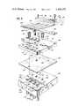
- FIG. 5is an exploded perspective view of a modified embodiment of the invention similar to the device shown in FIG. 4.
- the device 10provides for high speed operations and accuracy without residual motion.
- the piezoelectric drive mechanismthat provides the highspeed operation and accuracy, actuates the device 10 without being in contact with the fluid to be controlled, thereby avoiding mechanical and chemical problems with the piezoelectric member.
- the fluid control device 10includes a generally rectangular housing 12, a fluid inlet port 14, a fluid outlet port 16 and an electric power connection 18.
- a generally rectangular valve body 20having a chamber or passageway 22 communicating with the input port 14 andthe outlet port 16, a membrane 24, a mounting block 26, a piezoelectric driver mechanism 28, a impacting member 30, and clamping member 32.
- the fluidis contained entirely within the chamber 22 defined by the valve body 20 and the membrane 24, whereby the impacting member 30 and the piezoelectric driver mechanism 28 are separated from the fluid.
- the chamber 22 within the valve body 20is arranged to provide a valve seat 29.
- the valve seat 29is substantially coplanar with the generally planar surface 21 of the valve body 20.
- the membrane 24is a strong, pliable member and can be formed of a polymer material, such as the material sold under the registered trademark of Teflon by Dupont Company, or any of various elastomers or rubber.
- the material for the membrane 24must be selected on the basis of abrasion resistance, chemical compatability with the fluid, and elasticity and resilience characteristics.
- the membrane 24can be provided corresponding in dimensions to the rectangular valve body 20, except with a generally thin wall thickness, for example 0.015 inches.
- the membrane 24is secured to the upper, generally planar surface 21 of the valve body 20 and is arranged movably and resiliently in a vertical plane with the valve seat 29.
- the membrane 24functions as a gasket by sealing around the openings for mounting screws.
- the membrane 24provides a fluid-tight seal at the valve seat 29 with the impacting member 30 exerting a predetermined force on the membrane 24.
- Mounting screws 36are employed to couple the mounting block 26, membrane 24 and the valve body 20 and provide the clamping around the chamber. Openings 34 are provided in the membrane 24 to allow passage of a mountingscrews 36. Corresponding openings 38 are provided in the valve body 20 to receive the mounting screws 36. The use of the mounting screws 36 conveniently provide for changing the membrane 24 depending on the chemical nature of the fluid to be controlled.
- the mounting block 26is provided with openings 40 to receive the mounting screws 36. Second openings 42 are provided to receive mounting screws 44. The mounting screws 44 are employed to couple the clamping member 32, the piezoelectric drive mechanism 28, the spacer 52 and the mounting block 26.A third opening 46 is provided in the mounting block 26 to retain the impacting member 30 in position concentric with the valve seat 29 in the valve body 20 and in a vertical plane therewith.
- the mounting block 26canbe substantially equal in overall dimensions to the rectangular valve body 20.
- the piezoelectric driver mechanism 28is provided as a rectangular bar having overall dimensions less than the overall dimensions of the valve body 20.
- the piezoelectric driver mechanism 28is illustrated in FIGS. 2 and 3 as two like piezoelectric members 48A, 48B secured together.
- the number of the piezoelectric members 48A, 48B secured together in a stackdetermines the total force that can be generated by the driver mechanism 28.
- the total force that can be generated by the driver mechanism 28increases in proportion to the number of piezoelectric members 48A, 48B provided in the stack.
- the number of piezoelectric members 48A, 48Bis selected to satisfy the operating requirement of the particular application.
- the piezoelectric members 48A, 48Bare secured together and are connected electrically in parallel.
- the stack of two likepiezoelectric members 48A, 48Bcan provide a driver mechanism having a thickness of about 1/32 inch. Although illustrated as connected electrically in parallel, a series connection of the piezoelectric members48A and 48B is feasible within the skill in the art.
- the electrical power connection 18is provided to the upper and lower surfaces of the piezoelectric driver mechanism 28 and is connected to a variable D.C. power supply 50.
- the piezoelectric driver mechanism 28is mounted at its fixed end through a spacer 52 to the mounting block 26.
- Thefree-end of the piezoelectric driver mechanism 28is arranged to move toward and away from the impacting member 30 in predetermined relation to the polarity and level of the applied voltage.
- the amplitude of the movement or deflection of the free-end of the piezoelectric driver mechanism 28increases corresponding to increases in the level of the applied voltage, so that valve 10 can be used as a throttle valve by varying the level of the applied voltage.
- FIG. 2illustrates a normally closed valve 10; the piezoelectric driver mechanism 28 is mechanically deflected and holding the impacting member 30against the membrane 24, and membrane 24 against the valve seat 29 with thepower source 50 deactivated.
- the driver mechanism 28is arranged to provide a fluid-tight sealed engagement between the membrane 24 and the valve seat 29 with the electrical power source 50 deactivated.
- the free end of the piezoelectric drive mechanism 28is caused to further deflect and move away from the impacting member 30 by activating the electrical power source 50, thereby providing a path for fluid flow through chamber 22.
- the amount of fluid flowcan be controlled by varying the level of the voltage applied to the piezoelectric driver mechanism 28 and also, the time duration of the applied voltage.
- FIG. 3illustrates a normally open valve 10 wherein the piezoelectric driver mechanism 28 is arranged to provide a path for fluid flow through chamber 22 when the power source 50 is deactivated.
- the spacer 52is provided with additional height than is used for the normally closed valveillustrated in FIG. 2.
- the free-end of the piezoelectric driver mechanism 28is disposed at a higher position whereby the fluid flows frominlet port 14 through the chamber 22 and past valve seat 29 to the outlet port 16 with the power source 50 deactivated.
- the free end of the piezoelectric driver mechanism 28is caused to deflect and move toward theimpacting member 30 by activating the electrical power source 50, thereby throttling the fluid flow through chamber 22.
- the free end of the piezoelectric driver mechanism 28moves the impacting member 30 against the membrane 24, such that the membrane 24 exerts a fluid-tight sealing force on the valve seat 29 and closes chamber 22.
- the vertical dimension of the spacer 52can be used to provide for a normally closed or normally open valve with the polarity of the electricalconnection 18 determining the direction of movement of the deflectable portion of the piezoelectric drive mechanism 28.
- FIGS. 4 and 5modified forms of the invention are illustrated, each providing a plurality of fluid control devices with a housing 12.
- one inlet port 14' and seven outlet ports 16A, 16B, 16C, 16D, 16E, 16F, 16Gare provided.
- a separate and individual electrical connection 18'is provided to each of the seven fluid control devices thereby providing for separate and independent operation of each.
- FIG. 5is an exploded perspective view of a multiple valve body including four fluid control devices.
- the valve body 20'has a chamber 22' connecting the input port 14' to the four outlet ports 16A, 16B, 16C, 16D and is arranged to provide four valve seats 29A, 29B, 29C, 29D. Openings 38' are provided in the valve body 20' to receive mounting screws 36'.
- a membrane 24'is secured to the upper, generally planar surface of the valve body 20' and is arranged movable and resiliently in the vertical planes with the valve seats 29A, 29B, 29C, 29D.
- openings 34'are provided in the membrane 24' to allow passage of the mounting screws.
- a mounting block 26'is provided with openings 40' corresponding to openings 34' in the membrane 24' to receive the mounting screws 36' that couple the mounting block 26', the membrane 24' and valve body 20'.
- a pairof opening 42'are provided in the mounting block to receive mounting screws 44' that couple the mounting block 26' to clamping member 32' with the piezoelectric driver mechanism 28' and the spacer 52' secured therebetween.
- Openings 46A, 46B, 46C, 46Dare provided in the mounting block 26' to retain impacting members 30A, 30B, 30C, 30D and are disposed in the vertical planes with the valve seats 29A, 29B, 29C, 29D.
- the mounting block 26'can be substantially equal in overall dimensions to the valve body 20'.
- the piezoelectric driver mechanism 28'includes four electrically separate drivers 28A, 28B, 28C, 28D with a separate electrical power connection 18A, 18B, 18C, 18D provided to each for individual control.
- the piezoelectric drivers 28A, 28B, 28C, 28Dare illustrated as a stack of four like piezoelectric members 48A, 48B, 48C, 48D.
- a spacers 52'is employed to determine the separation between the free-ends of the piezoelectric driver mechanism 28A, 28B, 28C, 28D and the impacting members 30A, 30B, 30C, 30D to provide either all normally open or all normally closed valves as hereinbefore described for a single valve 10 as illustrated in FIGS. 1, 2 and 3.
- the multiple fluid control devices illustrated in FIGS. 4 and 5provide forindependent, high speed operation and accuracy without residual motion for each of the separate, closely-spaced valves.
- a multiple valve body(not shown) can be provided with a plurality of inlet ports corresponding to a plurality of outlet ports.
- Theprovision of multiple inlet portscould be useful in fluid control logic applications.
- Fluid control devices embodying the inventioncan be employed in a variety of different applications. Among such applications could be selective dispensing of inks, dyes or the like in the computer printing field, controlled dispensing of medicinals from pumps, implanted in a human for instance, controlling fluid flow in fluidic systems, among others.
- member 30has been illustrated as a sphere or ball to provide a surface which can cooperate with the valve seat 29 and membrane 24, it will be understood that member 30 may have a different configuration within the purview of the invention.
- member 30may be a cylinder or a flattened ball which presents such a cooperating surface with the valve seat, including the member 24.
- the impact member 30may have other useful configurations.
- the term "polyhedral-like member", as used herein,shall beconstrued to include any configuration of impact member suitable for the purposes described.
Landscapes
- Engineering & Computer Science (AREA)
- General Engineering & Computer Science (AREA)
- Mechanical Engineering (AREA)
- Physics & Mathematics (AREA)
- General Physics & Mathematics (AREA)
- Automation & Control Theory (AREA)
- Electrically Driven Valve-Operating Means (AREA)
- Flow Control (AREA)
- Valve Housings (AREA)
- Fluid-Pressure Circuits (AREA)
Abstract
Description
The invention herein relates generally to a fluid control device, and more particularly, to a device for rapid and accurate control of a fluid that is under pressure. The fluid to be controlled can be various gases or liquids.
It is known to use a piezoelectric element as a valve driver. Cummins, U.S. Pat. No. 4,340,083 discloses a valve including a piezoelectric bar arranged in the valve reservoir and mounted as a cantilevered beam with the free end of the piezoelectric bar being mounted for movement toward and away from a valve seat surrounding a control opening in response to the application of an electrical signal.
It is known to use a stack of piezoelectric discs as a driver for an undamped spring-mass system. Smiley, U.S. Pat. No. 3,614,486 discloses the use of a stack of thin piezoelectric discs as a driver for applications which require high speed, accuracy and virtually no vibration.
The known devices position the piezoelectric member in contact with the fluid. Thus, the known devices require protective coatings on the piezoelectric beam and electrical connections to protect the same from chemical attack by the fluid. Additionally, mechanical problems result from the fluid contact with the piezoelectric member.
The invention provides a fluid control device or valve including a piezoelectric transducer that functions to control the flow of the fluid. The invention herein differs from prior valves by providing the piezoelectric transducer outside the valve reservoir whereby the piezoelectric transducer does not contact the fluid and by providing a structure that is simple, economical to manufacture and highly effective for the intended purpose of rapidly and accurately controlling fluid flow.
A fluid control device is provided for use in selectively dispensing desired quantities a fluid that is contained under pressure. The piezoelectric device comprises a valve body having a fluid chamber and inlet and outlet means fluid communicating with said chamber with said inlet means adapted to be connected to a source of said fluid under pressure; and fluid control valve means for controlling such fluid dispensation through said outlet means comprising said body having at least one valve seat communicating with said outlet means; a deformable member mounted on said valve body in cooperation with said valve seat and impacting means engageable with said deformable member for selectively distorting said member proximate said valve seat so as to establish or disrupt such communication with said outlet means as desired; and piezoelectric means mounted on said valve body and adapted to be electrically connected to a D.C. source; said bender means having a deflectable portion engaging said impacting member which can be selectively moved upon energizing or deenergizing said bender means for selectively distorting the deformable member.
FIG. 1 is a partly schematic, perspective view of a fluid control device constructed in accordance with the invention;
FIG. 2 is an enlarged sectional detail of the device shown in FIG. 1, the housing normally enclosing the device being removed;
FIG. 3 in an enlarged sectional detail similar to FIG. 2 illustrating an alternate embodiment of the device of FIG. 1, the housing normally enclosing the device being removed;
FIG. 4 is a partly schematic, perspective view of a modified from of the invention providing a plurality of fluid control devices; and
FIG. 5 is an exploded perspective view of a modified embodiment of the invention similar to the device shown in FIG. 4.
Referring to FIGS. 1 and 2, there is illustrated a preferred embodiment of the invention that is identified generally by thereference character 10. Thedevice 10 provides for high speed operations and accuracy without residual motion. The piezoelectric drive mechanism, that provides the highspeed operation and accuracy, actuates thedevice 10 without being in contact with the fluid to be controlled, thereby avoiding mechanical and chemical problems with the piezoelectric member. Thefluid control device 10 includes a generallyrectangular housing 12, afluid inlet port 14, afluid outlet port 16 and anelectric power connection 18.
Enclosed within thehousing 12 are a generallyrectangular valve body 20 having a chamber orpassageway 22 communicating with theinput port 14andthe outlet port 16, amembrane 24, amounting block 26, apiezoelectric driver mechanism 28, a impactingmember 30, andclamping member 32. The fluid is contained entirely within thechamber 22 defined by thevalve body 20 and themembrane 24, whereby the impactingmember 30 and thepiezoelectric driver mechanism 28 are separated from the fluid. Thechamber 22 within thevalve body 20 is arranged to provide avalve seat 29. Thevalve seat 29 is substantially coplanar with the generally planar surface 21 of thevalve body 20.
Themembrane 24 is a strong, pliable member and can be formed of a polymer material, such as the material sold under the registered trademark of Teflon by Dupont Company, or any of various elastomers or rubber. The material for themembrane 24 must be selected on the basis of abrasion resistance, chemical compatability with the fluid, and elasticity and resilience characteristics. Themembrane 24 can be provided corresponding in dimensions to therectangular valve body 20, except with a generally thin wall thickness, for example 0.015 inches. Themembrane 24 is secured to the upper, generally planar surface 21 of thevalve body 20 and is arranged movably and resiliently in a vertical plane with thevalve seat 29. Themembrane 24 functions as a gasket by sealing around the openings for mounting screws. Themembrane 24 provides a fluid-tight seal at thevalve seat 29 with the impactingmember 30 exerting a predetermined force on themembrane 24.
Themounting block 26 is provided withopenings 40 to receive themounting screws 36.Second openings 42 are provided to receivemounting screws 44. Themounting screws 44 are employed to couple theclamping member 32, thepiezoelectric drive mechanism 28, thespacer 52 and the mounting block 26.Athird opening 46 is provided in themounting block 26 to retain the impactingmember 30 in position concentric with thevalve seat 29 in thevalve body 20 and in a vertical plane therewith. Themounting block 26 canbe substantially equal in overall dimensions to therectangular valve body 20.
Thepiezoelectric driver mechanism 28 is provided as a rectangular bar having overall dimensions less than the overall dimensions of thevalve body 20. Thepiezoelectric driver mechanism 28 is illustrated in FIGS. 2 and 3 as two likepiezoelectric members piezoelectric members driver mechanism 28. The total force that can be generated by thedriver mechanism 28 increases in proportion to the number ofpiezoelectric members piezoelectric members piezoelectric members likepiezoelectric members
Theelectrical power connection 18 is provided to the upper and lower surfaces of thepiezoelectric driver mechanism 28 and is connected to a variableD.C. power supply 50. Thepiezoelectric driver mechanism 28 is mounted at its fixed end through aspacer 52 to themounting block 26. Thefree-end of thepiezoelectric driver mechanism 28 is arranged to move toward and away from the impactingmember 30 in predetermined relation to the polarity and level of the applied voltage. The amplitude of the movement or deflection of the free-end of thepiezoelectric driver mechanism 28 increases corresponding to increases in the level of the applied voltage, so thatvalve 10 can be used as a throttle valve by varying the level of the applied voltage.
FIG. 2 illustrates a normally closedvalve 10; thepiezoelectric driver mechanism 28 is mechanically deflected and holding the impacting member 30against themembrane 24, andmembrane 24 against thevalve seat 29 withthepower source 50 deactivated. Thedriver mechanism 28 is arranged to providea fluid-tight sealed engagement between themembrane 24 and thevalve seat 29 with theelectrical power source 50 deactivated. The free end of thepiezoelectric drive mechanism 28 is caused to further deflect and move away from the impactingmember 30 by activating theelectrical power source 50, thereby providing a path for fluid flow throughchamber 22.
The amount of fluid flow can be controlled by varying the level of the voltage applied to thepiezoelectric driver mechanism 28 and also, the time duration of the applied voltage.
FIG. 3 illustrates a normallyopen valve 10 wherein thepiezoelectric driver mechanism 28 is arranged to provide a path for fluid flow throughchamber 22 when thepower source 50 is deactivated. Thespacer 52 is provided with additional height than is used for the normally closed valveillustrated in FIG. 2. Thus, the free-end of thepiezoelectric driver mechanism 28 is disposed at a higher position whereby the fluid flows frominletport 14 through thechamber 22 andpast valve seat 29 to theoutlet port 16 with thepower source 50 deactivated. The free end of thepiezoelectric driver mechanism 28 is caused to deflect and move towardtheimpacting member 30 by activating theelectrical power source 50, thereby throttling the fluid flow throughchamber 22. At a predetermined level of applied voltage, the free end of thepiezoelectric driver mechanism 28 moves the impactingmember 30 against themembrane 24, such that themembrane 24 exerts a fluid-tight sealing force on thevalve seat 29 and closeschamber 22.
The vertical dimension of thespacer 52 can be used to provide for a normally closed or normally open valve with the polarity of theelectricalconnection 18 determining the direction of movement of the deflectable portion of thepiezoelectric drive mechanism 28.
Referring to FIGS. 4 and 5, modified forms of the invention are illustrated, each providing a plurality of fluid control devices with ahousing 12.
In FIG. 4, one inlet port 14' and sevenoutlet ports
FIG. 5 is an exploded perspective view of a multiple valve body including four fluid control devices. The valve body 20' has a chamber 22' connecting the input port 14' to the fouroutlet ports valve seats
A mounting block 26' is provided with openings 40' corresponding to openings 34' in the membrane 24' to receive the mounting screws 36' that couple the mounting block 26', the membrane 24' and valve body 20'. A pairof opening 42' are provided in the mounting block to receive mounting screws 44' that couple the mounting block 26' to clamping member 32' with the piezoelectric driver mechanism 28' and the spacer 52' secured therebetween.
The piezoelectric driver mechanism 28' includes four electricallyseparate drivers electrical power connection piezoelectric drivers piezoelectric members piezoelectric driver mechanism members single valve 10 as illustrated in FIGS. 1, 2 and 3.
The multiple fluid control devices illustrated in FIGS. 4 and 5 provide forindependent, high speed operation and accuracy without residual motion for each of the separate, closely-spaced valves.
Alternatively, a multiple valve body (not shown) can be provided with a plurality of inlet ports corresponding to a plurality of outlet ports. Theprovision of multiple inlet ports could be useful in fluid control logic applications.
Fluid control devices embodying the invention can be employed in a variety of different applications. Among such applications could be selective dispensing of inks, dyes or the like in the computer printing field, controlled dispensing of medicinals from pumps, implanted in a human for instance, controlling fluid flow in fluidic systems, among others.
Although the impactingmember 30 has been illustrated as a sphere or ball to provide a surface which can cooperate with thevalve seat 29 andmembrane 24, it will be understood thatmember 30 may have a different configuration within the purview of the invention. For example,member 30 may be a cylinder or a flattened ball which presents such a cooperating surface with the valve seat, including themember 24. Obviously, theimpact member 30 may have other useful configurations. For descriptive purposes only, the term "polyhedral-like member", as used herein, shall beconstrued to include any configuration of impact member suitable for the purposes described.
Many other variations are capable of being made without departing from the spirit or scope of the invention as defined in the appended claims.
Claims (14)
1. A piezoelectric device for selectively dispensing desired quantities of a fluid under pressure comprising:
A. a valve body having a fluid chamber and inlet and outlet means communicating with said chamber with said inlet means adapted to be connected to a source of said fluid under pressure; and
B. fluid control valve means for controlling such fluid dispensation through said outlet means comprising:
I. said body having at least one valve seat communicating with said outlet means;
II. a deformable member mounted on the valve body in cooperation with said valve seat effective to control communication with said outlet means about said valve seat and impacting means directly engageable with the deformable member for selectively distorting said member proximate said valve seat to change the condition of said deformable member about said valve seat so as to establish or disrupt such communication with said outlet means as desired; and
C. piezoelectric bender means mounted on the valve body isolated from said fluid chamber and adapted to be electrically connected to a D.C. source; said bender means including a deflectable portion engaging said impacting means to move same selectively upon energizing or deenergizing of said piezoelectric bender means for selectively distorting the deformable member without either said impacting means or said bender means contacting said fluid.
2. A device as described in claim 1 in which said deformable member comprises a membrane and said impacting means comprises a member having a surface complementary with said valve seat.
3. A device as described in claim 1 in which said outlet means comprise a plurality of separate outlets each communicating with said chamber; and said device includes a like plurality of valve seats, impacting means and bender means cooperating with said deformable member for selectively dispensing fluid from said separate outlets upon energizing or deenergizing said bender means.
4. A device as described in claim 3 in which said deformable member comprises a membrane and said impacting means comprise a plurality of members each having a surface complementary with a respective valve seat.
5. A device as described in claim 1 in which said impacting means comprises a polyhedral-like member.
6. A device as described in claim 3 in which said impacting means comprise polyhedral-like members.
7. A device as described in claim 1 in which said impacting means comprise a ball member.
8. A device as described in claim 3 in which said impacting means comprise plural balls.
9. A device as described in claim 1 in which said bender means comprises a piezoceramic wafer anchored at one end thereof on said valve body and said deflectable portion is adjacent the opposite end of the wafer.
10. A device as described in claim 3 in which said bender means comprise a plurality of piezoceramic wafers anchored at one end thereof on said valve body and said deflectable portions are adjacent the opposite ends of the wafers.
11. The device as described in claim 1 in which said valve body includes a mounting plate having said impacting means supported thereby in registry with said valve seat.
12. The device as described in claim 3 in which said valve body includes a mounting plate having said impacting means supported thereby in registry with said valve seats.
13. The device as described in claim 1 in which said deformable member is a diaphram formed of one of an elastomer and rubber material.
14. The device as described in claim 3 in which said deformable member is a diaphram formed of one of an elastomer and rubber material.
Priority Applications (14)
| Application Number | Priority Date | Filing Date | Title |
|---|---|---|---|
| US06/440,966US4450375A (en) | 1982-11-12 | 1982-11-12 | Piezoelectric fluid control device |
| EP19830306728EP0109239B1 (en) | 1982-11-12 | 1983-11-04 | Piezoelectric fluid control device |
| DE8383306728TDE3371113D1 (en) | 1982-11-12 | 1983-11-04 | Piezoelectric fluid control device |
| AT83306728TATE26749T1 (en) | 1982-11-12 | 1983-11-04 | PIEZO ELECTRIC FLUID CONTROLLER. |
| GB8329539AGB2131130B (en) | 1982-11-12 | 1983-11-04 | Piezoelectric fluid control device |
| CA000440942ACA1218640A (en) | 1982-11-12 | 1983-11-10 | Piezoelectric fluid control device |
| KR1019830005358AKR890000076B1 (en) | 1982-11-12 | 1983-11-11 | Fluid controller |
| ZA838426AZA838426B (en) | 1982-11-12 | 1983-11-11 | Piezoelectric fluid control device |
| AU21177/83AAU559913B2 (en) | 1982-11-12 | 1983-11-11 | Piezoelectric fluid flow control device |
| IL7020083AIL70200A (en) | 1982-11-12 | 1983-11-11 | Piezoelectric fluid control device |
| DK516383ADK516383A (en) | 1982-11-12 | 1983-11-11 | DEVICE FOR CONTROL OF FLUIDUM FLOW |
| JP58211120AJPS59140980A (en) | 1982-11-12 | 1983-11-11 | Piezoelectric type fluid controller |
| IE2642/83AIE54778B1 (en) | 1982-11-12 | 1983-11-11 | Piezoelectric fluid control device |
| HK846/86AHK84686A (en) | 1982-11-12 | 1986-11-06 | Piezoelectric fluid control device |
Applications Claiming Priority (1)
| Application Number | Priority Date | Filing Date | Title |
|---|---|---|---|
| US06/440,966US4450375A (en) | 1982-11-12 | 1982-11-12 | Piezoelectric fluid control device |
Publications (1)
| Publication Number | Publication Date |
|---|---|
| US4450375Atrue US4450375A (en) | 1984-05-22 |
Family
ID=23750950
Family Applications (1)
| Application Number | Title | Priority Date | Filing Date |
|---|---|---|---|
| US06/440,966Expired - Fee RelatedUS4450375A (en) | 1982-11-12 | 1982-11-12 | Piezoelectric fluid control device |
Country Status (14)
| Country | Link |
|---|---|
| US (1) | US4450375A (en) |
| EP (1) | EP0109239B1 (en) |
| JP (1) | JPS59140980A (en) |
| KR (1) | KR890000076B1 (en) |
| AT (1) | ATE26749T1 (en) |
| AU (1) | AU559913B2 (en) |
| CA (1) | CA1218640A (en) |
| DE (1) | DE3371113D1 (en) |
| DK (1) | DK516383A (en) |
| GB (1) | GB2131130B (en) |
| HK (1) | HK84686A (en) |
| IE (1) | IE54778B1 (en) |
| IL (1) | IL70200A (en) |
| ZA (1) | ZA838426B (en) |
Cited By (87)
| Publication number | Priority date | Publication date | Assignee | Title |
|---|---|---|---|---|
| US4567394A (en)* | 1983-01-13 | 1986-01-28 | Enfo Grundlagenforschungs Ag | Electro-pneumatic signal converter |
| US4575697A (en)* | 1984-06-18 | 1986-03-11 | Sperry Corporation | Electrically controlled phase shifter |
| US4620123A (en)* | 1984-12-21 | 1986-10-28 | General Electric Company | Synchronously operable electrical current switching apparatus having multiple circuit switching capability and/or reduced contact resistance |
| US4625139A (en)* | 1985-02-08 | 1986-11-25 | Enfo Grundlagenforschungs Ag | Electro-pneumatic signal converter |
| US4629926A (en)* | 1985-10-21 | 1986-12-16 | Kiwi Coders Corporation | Mounting for piezoelectric bender of fluid control device |
| US4633121A (en)* | 1984-05-29 | 1986-12-30 | Ngk Spark Plug Co., Ltd. | Comb-shaped piezoelectric drive device |
| US4654555A (en)* | 1983-09-05 | 1987-03-31 | Omron Tateisi Electronics Co. | Multi pole piezoelectrically operating relay |
| US4697118A (en)* | 1986-08-15 | 1987-09-29 | General Electric Company | Piezoelectric switch |
| US4723131A (en)* | 1986-09-12 | 1988-02-02 | Diagraph Corporation | Printhead for ink jet printing apparatus |
| US4758226A (en)* | 1986-04-18 | 1988-07-19 | Maurice Carre | Device for distribution, particularly for medical use, of a product in predetermined metered amounts |
| US4771204A (en)* | 1987-07-30 | 1988-09-13 | Kiwi Coders Corporation | Sealing method and means for fluid control device |
| US4808874A (en)* | 1988-01-06 | 1989-02-28 | Ford Aerospace Corporation | Double saggital stroke amplifier |
| US4809017A (en)* | 1987-01-07 | 1989-02-28 | Domino Printing Sciences Plc | Ink jet printing head |
| US4841256A (en)* | 1987-10-20 | 1989-06-20 | Pennwalt Corporation | Piezoelectric phase locked loop circuit |
| US4933591A (en)* | 1988-01-06 | 1990-06-12 | Ford Aerospace Corporation | Double saggital pull stroke amplifier |
| US5094594A (en)* | 1990-04-23 | 1992-03-10 | Genomyx, Incorporated | Piezoelectric pumping device |
| US5144332A (en)* | 1989-04-17 | 1992-09-01 | Komori Corporation | Method of controlling head in image recording apparatus |
| EP0506232A1 (en)* | 1991-03-26 | 1992-09-30 | Videojet Systems International, Inc. | Valve assembly for ink jet printer |
| EP0541294A3 (en)* | 1991-11-06 | 1993-08-25 | Brother Kogyo Kabushiki Kaisha | Droplet ejecting device |
| US5585011A (en)* | 1993-10-04 | 1996-12-17 | Research International, Inc. | Methods for manufacturing a filter |
| WO2000031529A1 (en)* | 1998-11-20 | 2000-06-02 | Akzo Nobel N.V. | Devices and methods for performing blood coagulation assays by piezoelectric sensing |
| US6082185A (en)* | 1997-07-25 | 2000-07-04 | Research International, Inc. | Disposable fluidic circuit cards |
| US6131879A (en)* | 1996-11-25 | 2000-10-17 | Fraunhofer-Gesellschaft Zur Forderung Der Angewandten Forschung E.V. | Piezoelectrically actuated microvalve |
| US6142444A (en)* | 1996-11-25 | 2000-11-07 | Fraunhofer-Gesellschaft Zur Forderung Der Angewandten Forschung E.V. | Piezoelectrically actuated microvalve |
| CN1084856C (en)* | 1997-07-11 | 2002-05-15 | Smc株式会社 | Opening and closing valve |
| EP1207329A1 (en)* | 2000-11-20 | 2002-05-22 | FESTO AG & Co | Piezo valve |
| WO2002041413A1 (en)* | 2000-11-20 | 2002-05-23 | Festo Ag & Co | Piezo flexural transducer unit and piezo valve which is equipped with the same |
| US20040003786A1 (en)* | 2002-06-18 | 2004-01-08 | Gatecliff George W. | Piezoelectric valve actuation |
| WO2005084952A1 (en)* | 2004-03-03 | 2005-09-15 | Rea Elektronik Gmbh | Ink-jet printing element |
| US20050199301A1 (en)* | 2004-02-11 | 2005-09-15 | Festo Ag & Co. | Piezoelectric valve |
| WO2005098289A1 (en)* | 2004-04-07 | 2005-10-20 | Siemens Aktiengesellschaft | Device and method for actuating a valve in a micromechanical appliance |
| WO2005110759A1 (en)* | 2004-05-11 | 2005-11-24 | Rea Elektronik Gmbh | Ink jet write head |
| US20060054123A1 (en)* | 2004-03-02 | 2006-03-16 | Ab Skf | Oil separator |
| US20070269324A1 (en)* | 2004-11-24 | 2007-11-22 | O-Core Ltd. | Finger-Type Peristaltic Pump |
| US20080095649A1 (en)* | 2002-11-14 | 2008-04-24 | Zvi Ben-Shalom | Peristaltic Pump |
| US7475607B2 (en)* | 2004-01-08 | 2009-01-13 | Honeywell International Inc. | Sensing apparatus with an integrated gasket on a beam component |
| US20090082793A1 (en)* | 2004-01-23 | 2009-03-26 | Allergan, Inc. | Releasably-securable one-piece adjustable gastric band |
| US20090221964A1 (en)* | 2004-11-24 | 2009-09-03 | Q-Core Medical Ltd | Peristaltic infusion pump with locking mechanism |
| US7594663B2 (en) | 1997-05-20 | 2009-09-29 | Zymequest, Inc. | Rotating seals for cell processing systems |
| US20090317268A1 (en)* | 2006-11-13 | 2009-12-24 | Q-Core Medical Ltd | Finger-type peristaltic pump comprising a ribbed anvil |
| US20100036322A1 (en)* | 2006-11-13 | 2010-02-11 | Q-Core Medical Ltd. | Anti-free flow mechanism |
| US20100099945A1 (en)* | 2008-10-22 | 2010-04-22 | Allergan, Inc. | Electrically activated valve for implantable fluid handling system |
| US20100274274A1 (en)* | 2005-04-13 | 2010-10-28 | Allergan, Inc. | Artificial gastric valve |
| US20100305397A1 (en)* | 2008-10-06 | 2010-12-02 | Allergan Medical Sarl | Hydraulic-mechanical gastric band |
| US20110152772A1 (en)* | 2009-12-22 | 2011-06-23 | Q-Core Medical Ltd | Peristaltic Pump with Bi-Directional Pressure Sensor |
| US20110152831A1 (en)* | 2009-12-22 | 2011-06-23 | Q-Core Medical Ltd | Peristaltic Pump with Linear Flow Control |
| US20110201875A1 (en)* | 2010-02-12 | 2011-08-18 | Allergan, Inc. | Remotely adjustable gastric banding system |
| US20110201874A1 (en)* | 2010-02-12 | 2011-08-18 | Allergan, Inc. | Remotely adjustable gastric banding system |
| US20110207995A1 (en)* | 2010-02-25 | 2011-08-25 | Allergan, Inc. | Inductively powered remotely adjustable gastric banding system |
| US20110208220A1 (en)* | 2010-02-25 | 2011-08-25 | Allergan, Inc. | Pressure sensing gastric banding system |
| US8317677B2 (en) | 2008-10-06 | 2012-11-27 | Allergan, Inc. | Mechanical gastric band with cushions |
| US8377081B2 (en) | 2004-03-08 | 2013-02-19 | Allergan, Inc. | Closure system for tubular organs |
| US8382780B2 (en) | 2002-08-28 | 2013-02-26 | Allergan, Inc. | Fatigue-resistant gastric banding device |
| US8517915B2 (en) | 2010-06-10 | 2013-08-27 | Allergan, Inc. | Remotely adjustable gastric banding system |
| US8535025B2 (en) | 2006-11-13 | 2013-09-17 | Q-Core Medical Ltd. | Magnetically balanced finger-type peristaltic pump |
| US20130271538A1 (en)* | 2011-01-07 | 2013-10-17 | Patrick V. Boyd | Integrated multifunctional valve device |
| US8698373B2 (en) | 2010-08-18 | 2014-04-15 | Apollo Endosurgery, Inc. | Pare piezo power with energy recovery |
| US8758221B2 (en) | 2010-02-24 | 2014-06-24 | Apollo Endosurgery, Inc. | Source reservoir with potential energy for remotely adjustable gastric banding system |
| US8845513B2 (en) | 2002-08-13 | 2014-09-30 | Apollo Endosurgery, Inc. | Remotely adjustable gastric banding device |
| US8876694B2 (en) | 2011-12-07 | 2014-11-04 | Apollo Endosurgery, Inc. | Tube connector with a guiding tip |
| US8900118B2 (en) | 2008-10-22 | 2014-12-02 | Apollo Endosurgery, Inc. | Dome and screw valves for remotely adjustable gastric banding systems |
| US8905915B2 (en) | 2006-01-04 | 2014-12-09 | Apollo Endosurgery, Inc. | Self-regulating gastric band with pressure data processing |
| US8961394B2 (en) | 2011-12-20 | 2015-02-24 | Apollo Endosurgery, Inc. | Self-sealing fluid joint for use with a gastric band |
| US9028394B2 (en) | 2010-04-29 | 2015-05-12 | Apollo Endosurgery, Inc. | Self-adjusting mechanical gastric band |
| US9044298B2 (en) | 2010-04-29 | 2015-06-02 | Apollo Endosurgery, Inc. | Self-adjusting gastric band |
| US9050165B2 (en) | 2010-09-07 | 2015-06-09 | Apollo Endosurgery, Inc. | Remotely adjustable gastric banding system |
| US9090082B2 (en) | 2011-01-07 | 2015-07-28 | Hewlett-Packard Development Company, L.P. | Fluid container having plurality of chambers |
| US9211207B2 (en) | 2010-08-18 | 2015-12-15 | Apollo Endosurgery, Inc. | Power regulated implant |
| US9226840B2 (en) | 2010-06-03 | 2016-01-05 | Apollo Endosurgery, Inc. | Magnetically coupled implantable pump system and method |
| US9295573B2 (en) | 2010-04-29 | 2016-03-29 | Apollo Endosurgery, Inc. | Self-adjusting gastric band having various compliant components and/or a satiety booster |
| US9315030B2 (en) | 2011-01-07 | 2016-04-19 | Hewlett-Packard Development Company, L.P. | Fluid container having plurality of chambers and valves |
| CN105782459A (en)* | 2014-12-19 | 2016-07-20 | 昆达电脑科技(昆山)有限公司 | Valve realizing automatic opening and closing based on humidity |
| US9457158B2 (en) | 2010-04-12 | 2016-10-04 | Q-Core Medical Ltd. | Air trap for intravenous pump |
| US9674811B2 (en) | 2011-01-16 | 2017-06-06 | Q-Core Medical Ltd. | Methods, apparatus and systems for medical device communication, control and localization |
| USRE46499E1 (en)* | 2001-07-03 | 2017-08-01 | Face International Corporation | Self-powered switch initiation system |
| US9726167B2 (en) | 2011-06-27 | 2017-08-08 | Q-Core Medical Ltd. | Methods, circuits, devices, apparatuses, encasements and systems for identifying if a medical infusion system is decalibrated |
| TWI599868B (en)* | 2016-09-05 | 2017-09-21 | 研能科技股份有限公司 | Manufacturing method of fluid control device |
| US9855110B2 (en) | 2013-02-05 | 2018-01-02 | Q-Core Medical Ltd. | Methods, apparatus and systems for operating a medical device including an accelerometer |
| US10994535B2 (en) | 2018-05-11 | 2021-05-04 | Matthews International Corporation | Systems and methods for controlling operation of micro-valves for use in jetting assemblies |
| US20210323005A1 (en)* | 2020-04-19 | 2021-10-21 | Exel Industries Sa | Print head comprising a micro-pneumatic control unit |
| US11186084B2 (en) | 2018-05-11 | 2021-11-30 | Matthews International Corporation | Electrode structures for micro-valves for use in jetting assemblies |
| US11479041B2 (en) | 2018-05-11 | 2022-10-25 | Matthews International Corporation | Systems and methods for sealing micro-valves for use in jetting assemblies |
| US11639057B2 (en) | 2018-05-11 | 2023-05-02 | Matthews International Corporation | Methods of fabricating micro-valves and jetting assemblies including such micro-valves |
| US11679189B2 (en) | 2019-11-18 | 2023-06-20 | Eitan Medical Ltd. | Fast test for medical pump |
| US11794476B2 (en) | 2018-05-11 | 2023-10-24 | Matthews International Corporation | Micro-valves for use in jetting assemblies |
| IT202300002931A1 (en)* | 2023-02-21 | 2024-08-21 | Camozzi Automation S P A | PIEZO VALVE |
| US12358014B2 (en) | 2019-11-01 | 2025-07-15 | Matthews International Corporation | Non-contact deposition systems including jetting assemblies |
Families Citing this family (8)
| Publication number | Priority date | Publication date | Assignee | Title |
|---|---|---|---|---|
| DE3428969A1 (en)* | 1984-08-06 | 1986-02-13 | Siemens AG, 1000 Berlin und 8000 München | CONTROL VALVE FOR AIR VALVE ACTUATION |
| DE3814150A1 (en)* | 1988-04-27 | 1989-11-09 | Draegerwerk Ag | VALVE ARRANGEMENT MADE FROM MICROSTRUCTURED COMPONENTS |
| US6394412B2 (en) | 1993-04-02 | 2002-05-28 | Netafim (A.C.S.) Ltd. | Controlled valve |
| DE19723388C1 (en)* | 1997-06-04 | 1998-07-02 | Draegerwerk Ag | Modular piezo valve arrangement for medical gas mixers or ventilators |
| SE9904264D0 (en)* | 1999-11-25 | 1999-11-25 | Markpoint Ab | valve device |
| WO2014060845A1 (en)* | 2012-09-12 | 2014-04-24 | Funai Electric Co., Ltd. | Maintenance valves for micro-fluid ejection heads |
| GB2516847A (en)* | 2013-07-31 | 2015-02-11 | Ingegneria Ceramica S R L | An Improved Actuator For A Printhead |
| GB2583059B (en)* | 2019-01-30 | 2024-01-31 | Cn Bio Innovations Ltd | A microvalve, and a multi-directional valve apparatus |
Citations (4)
| Publication number | Priority date | Publication date | Assignee | Title |
|---|---|---|---|---|
| US4011474A (en)* | 1974-10-03 | 1977-03-08 | Pz Technology, Inc. | Piezoelectric stack insulation |
| US4032929A (en)* | 1975-10-28 | 1977-06-28 | Xerox Corporation | High density linear array ink jet assembly |
| US4072959A (en)* | 1975-06-20 | 1978-02-07 | Siemens Aktiengesellschaft | Recorder operating with drops of liquid |
| US4318023A (en)* | 1980-02-21 | 1982-03-02 | Physics International Company | Sagittally amplified piezoelectric actuator |
Family Cites Families (15)
| Publication number | Priority date | Publication date | Assignee | Title |
|---|---|---|---|---|
| GB853469A (en)* | 1955-12-21 | 1960-11-09 | Baird & Tatlock Ltd | Improvements in or relating to valves for controlling fluid flow |
| GB901226A (en)* | 1959-01-16 | 1962-07-18 | Council Scient Ind Res | Improvements in fluid flow controllers |
| GB963051A (en)* | 1961-10-16 | 1964-07-08 | Jose Marlet Barrera | Improved valve for liquids |
| US3456669A (en)* | 1966-10-20 | 1969-07-22 | Fisher Governor Co | Piezoelectric transducer |
| GB1270879A (en)* | 1969-10-30 | 1972-04-19 | Santon Ltd | Electrically controlled valve |
| US3614486A (en)* | 1969-11-10 | 1971-10-19 | Physics Int Co | Lever motion multiplier driven by electroexpansive material |
| DE2042066B2 (en)* | 1970-08-25 | 1971-10-14 | Mersch Fonderies Atel | DIAPHRAGM VALVE |
| DE2226365A1 (en)* | 1971-06-02 | 1972-12-14 | British Oxygen Co Ltd | Inlet valve, especially for vacuum tanks |
| DE2426748C3 (en)* | 1974-06-01 | 1979-10-11 | Buerkert Gmbh, 7118 Ingelfingen | Multi-way solenoid valve for aggressive media |
| US4099700A (en)* | 1977-02-16 | 1978-07-11 | Wen Young | Flow control device for fluids flowing in a closed conduit |
| DE2752549A1 (en)* | 1977-11-24 | 1979-06-07 | Boehringer Mannheim Gmbh | VALVE FOR THE CONTROL OF FLOW MEDIA |
| GB1593495A (en)* | 1978-02-24 | 1981-07-15 | Ti Domestic Appliances Ltd | Thermally actuated gas flow control valve assemblies |
| US4340083A (en)* | 1978-11-30 | 1982-07-20 | Carleton Controls Corporation | Deflectable beam valve |
| DE2918377A1 (en)* | 1979-05-07 | 1980-11-20 | Schenck Ag Carl | Flow control valve for HF range with precise regulation - uses piezoelectric element directly or indirectly varying cross=section of stream |
| JPS57136859U (en)* | 1981-02-18 | 1982-08-26 |
- 1982
- 1982-11-12USUS06/440,966patent/US4450375A/ennot_activeExpired - Fee Related
- 1983
- 1983-11-04GBGB8329539Apatent/GB2131130B/ennot_activeExpired
- 1983-11-04EPEP19830306728patent/EP0109239B1/ennot_activeExpired
- 1983-11-04ATAT83306728Tpatent/ATE26749T1/ennot_activeIP Right Cessation
- 1983-11-04DEDE8383306728Tpatent/DE3371113D1/ennot_activeExpired
- 1983-11-10CACA000440942Apatent/CA1218640A/ennot_activeExpired
- 1983-11-11JPJP58211120Apatent/JPS59140980A/enactivePending
- 1983-11-11DKDK516383Apatent/DK516383A/ennot_activeApplication Discontinuation
- 1983-11-11IEIE2642/83Apatent/IE54778B1/enunknown
- 1983-11-11ILIL7020083Apatent/IL70200A/enunknown
- 1983-11-11AUAU21177/83Apatent/AU559913B2/ennot_activeCeased
- 1983-11-11ZAZA838426Apatent/ZA838426B/enunknown
- 1983-11-11KRKR1019830005358Apatent/KR890000076B1/ennot_activeExpired
- 1986
- 1986-11-06HKHK846/86Apatent/HK84686A/enunknown
Patent Citations (4)
| Publication number | Priority date | Publication date | Assignee | Title |
|---|---|---|---|---|
| US4011474A (en)* | 1974-10-03 | 1977-03-08 | Pz Technology, Inc. | Piezoelectric stack insulation |
| US4072959A (en)* | 1975-06-20 | 1978-02-07 | Siemens Aktiengesellschaft | Recorder operating with drops of liquid |
| US4032929A (en)* | 1975-10-28 | 1977-06-28 | Xerox Corporation | High density linear array ink jet assembly |
| US4318023A (en)* | 1980-02-21 | 1982-03-02 | Physics International Company | Sagittally amplified piezoelectric actuator |
Cited By (129)
| Publication number | Priority date | Publication date | Assignee | Title |
|---|---|---|---|---|
| US4567394A (en)* | 1983-01-13 | 1986-01-28 | Enfo Grundlagenforschungs Ag | Electro-pneumatic signal converter |
| US4654555A (en)* | 1983-09-05 | 1987-03-31 | Omron Tateisi Electronics Co. | Multi pole piezoelectrically operating relay |
| US4633121A (en)* | 1984-05-29 | 1986-12-30 | Ngk Spark Plug Co., Ltd. | Comb-shaped piezoelectric drive device |
| US4575697A (en)* | 1984-06-18 | 1986-03-11 | Sperry Corporation | Electrically controlled phase shifter |
| US4620123A (en)* | 1984-12-21 | 1986-10-28 | General Electric Company | Synchronously operable electrical current switching apparatus having multiple circuit switching capability and/or reduced contact resistance |
| US4625139A (en)* | 1985-02-08 | 1986-11-25 | Enfo Grundlagenforschungs Ag | Electro-pneumatic signal converter |
| US4629926A (en)* | 1985-10-21 | 1986-12-16 | Kiwi Coders Corporation | Mounting for piezoelectric bender of fluid control device |
| WO1987002514A1 (en)* | 1985-10-21 | 1987-04-23 | Kiwi Coders Corporation | Mounting for piezoelectric bender of fluid control device |
| US4758226A (en)* | 1986-04-18 | 1988-07-19 | Maurice Carre | Device for distribution, particularly for medical use, of a product in predetermined metered amounts |
| US4697118A (en)* | 1986-08-15 | 1987-09-29 | General Electric Company | Piezoelectric switch |
| US4723131A (en)* | 1986-09-12 | 1988-02-02 | Diagraph Corporation | Printhead for ink jet printing apparatus |
| US4809017A (en)* | 1987-01-07 | 1989-02-28 | Domino Printing Sciences Plc | Ink jet printing head |
| US4771204A (en)* | 1987-07-30 | 1988-09-13 | Kiwi Coders Corporation | Sealing method and means for fluid control device |
| WO1989001241A1 (en)* | 1987-07-30 | 1989-02-09 | Kiwi Coders Corporation | Sealing method and means for fluid control device |
| US4841256A (en)* | 1987-10-20 | 1989-06-20 | Pennwalt Corporation | Piezoelectric phase locked loop circuit |
| US4808874A (en)* | 1988-01-06 | 1989-02-28 | Ford Aerospace Corporation | Double saggital stroke amplifier |
| US4933591A (en)* | 1988-01-06 | 1990-06-12 | Ford Aerospace Corporation | Double saggital pull stroke amplifier |
| US5144332A (en)* | 1989-04-17 | 1992-09-01 | Komori Corporation | Method of controlling head in image recording apparatus |
| US5094594A (en)* | 1990-04-23 | 1992-03-10 | Genomyx, Incorporated | Piezoelectric pumping device |
| EP0506232A1 (en)* | 1991-03-26 | 1992-09-30 | Videojet Systems International, Inc. | Valve assembly for ink jet printer |
| EP0541294A3 (en)* | 1991-11-06 | 1993-08-25 | Brother Kogyo Kabushiki Kaisha | Droplet ejecting device |
| US5434608A (en)* | 1991-11-06 | 1995-07-18 | Brother Kogyo Kabushiki Kaisha | Droplet ejecting device |
| US5660728A (en)* | 1993-10-04 | 1997-08-26 | Research International, Inc. | Micromachined fluid handling apparatus with filter |
| US5585011A (en)* | 1993-10-04 | 1996-12-17 | Research International, Inc. | Methods for manufacturing a filter |
| US5617632A (en)* | 1993-10-04 | 1997-04-08 | Research International, Inc. | Methods for forming a contoured regulator seat |
| US5697153A (en)* | 1993-10-04 | 1997-12-16 | Research International, Inc. | Method for manufacturing a fluid flow regulator |
| US5702618A (en)* | 1993-10-04 | 1997-12-30 | Research International, Inc. | Methods for manufacturing a flow switch |
| US5705070A (en)* | 1993-10-04 | 1998-01-06 | Research International, Inc. | Micromachined filters |
| US5839467A (en)* | 1993-10-04 | 1998-11-24 | Research International, Inc. | Micromachined fluid handling devices |
| US6142444A (en)* | 1996-11-25 | 2000-11-07 | Fraunhofer-Gesellschaft Zur Forderung Der Angewandten Forschung E.V. | Piezoelectrically actuated microvalve |
| US6131879A (en)* | 1996-11-25 | 2000-10-17 | Fraunhofer-Gesellschaft Zur Forderung Der Angewandten Forschung E.V. | Piezoelectrically actuated microvalve |
| US20090309308A1 (en)* | 1997-05-20 | 2009-12-17 | Zymequest, Inc. | Rotating seals for cell processing systems |
| US7594663B2 (en) | 1997-05-20 | 2009-09-29 | Zymequest, Inc. | Rotating seals for cell processing systems |
| CN1084856C (en)* | 1997-07-11 | 2002-05-15 | Smc株式会社 | Opening and closing valve |
| US6082185A (en)* | 1997-07-25 | 2000-07-04 | Research International, Inc. | Disposable fluidic circuit cards |
| WO2000031529A1 (en)* | 1998-11-20 | 2000-06-02 | Akzo Nobel N.V. | Devices and methods for performing blood coagulation assays by piezoelectric sensing |
| WO2002041413A1 (en)* | 2000-11-20 | 2002-05-23 | Festo Ag & Co | Piezo flexural transducer unit and piezo valve which is equipped with the same |
| US6581638B2 (en) | 2000-11-20 | 2003-06-24 | Festo Ag & Co. | Piezo valve |
| EP1207329A1 (en)* | 2000-11-20 | 2002-05-22 | FESTO AG & Co | Piezo valve |
| KR100824567B1 (en)* | 2000-11-20 | 2008-04-23 | 훼스토 악티엔 게젤샤프트 운트 코 | Piezoelectric valve |
| USRE46499E1 (en)* | 2001-07-03 | 2017-08-01 | Face International Corporation | Self-powered switch initiation system |
| US20040003786A1 (en)* | 2002-06-18 | 2004-01-08 | Gatecliff George W. | Piezoelectric valve actuation |
| US8845513B2 (en) | 2002-08-13 | 2014-09-30 | Apollo Endosurgery, Inc. | Remotely adjustable gastric banding device |
| US8382780B2 (en) | 2002-08-28 | 2013-02-26 | Allergan, Inc. | Fatigue-resistant gastric banding device |
| US7695255B2 (en) | 2002-11-14 | 2010-04-13 | Q-Core Medical Ltd | Peristaltic pump |
| US20080095649A1 (en)* | 2002-11-14 | 2008-04-24 | Zvi Ben-Shalom | Peristaltic Pump |
| US7475607B2 (en)* | 2004-01-08 | 2009-01-13 | Honeywell International Inc. | Sensing apparatus with an integrated gasket on a beam component |
| US8900117B2 (en) | 2004-01-23 | 2014-12-02 | Apollo Endosurgery, Inc. | Releasably-securable one-piece adjustable gastric band |
| US20090082793A1 (en)* | 2004-01-23 | 2009-03-26 | Allergan, Inc. | Releasably-securable one-piece adjustable gastric band |
| US7322376B2 (en)* | 2004-02-11 | 2008-01-29 | Festo Ag & Co. | Piezoelectric valve |
| US20050199301A1 (en)* | 2004-02-11 | 2005-09-15 | Festo Ag & Co. | Piezoelectric valve |
| US7415953B2 (en)* | 2004-03-02 | 2008-08-26 | Ab Skf | Oil separator |
| US20060054123A1 (en)* | 2004-03-02 | 2006-03-16 | Ab Skf | Oil separator |
| WO2005084952A1 (en)* | 2004-03-03 | 2005-09-15 | Rea Elektronik Gmbh | Ink-jet printing element |
| US8377081B2 (en) | 2004-03-08 | 2013-02-19 | Allergan, Inc. | Closure system for tubular organs |
| WO2005098289A1 (en)* | 2004-04-07 | 2005-10-20 | Siemens Aktiengesellschaft | Device and method for actuating a valve in a micromechanical appliance |
| US20080246821A1 (en)* | 2004-05-11 | 2008-10-09 | Manfred Pauly | Ink Jet Write Head |
| WO2005110759A1 (en)* | 2004-05-11 | 2005-11-24 | Rea Elektronik Gmbh | Ink jet write head |
| US8029253B2 (en) | 2004-11-24 | 2011-10-04 | Q-Core Medical Ltd. | Finger-type peristaltic pump |
| US20090221964A1 (en)* | 2004-11-24 | 2009-09-03 | Q-Core Medical Ltd | Peristaltic infusion pump with locking mechanism |
| US9657902B2 (en) | 2004-11-24 | 2017-05-23 | Q-Core Medical Ltd. | Peristaltic infusion pump with locking mechanism |
| US9404490B2 (en) | 2004-11-24 | 2016-08-02 | Q-Core Medical Ltd. | Finger-type peristaltic pump |
| US20070269324A1 (en)* | 2004-11-24 | 2007-11-22 | O-Core Ltd. | Finger-Type Peristaltic Pump |
| US10184615B2 (en) | 2004-11-24 | 2019-01-22 | Q-Core Medical Ltd. | Peristaltic infusion pump with locking mechanism |
| US8678793B2 (en) | 2004-11-24 | 2014-03-25 | Q-Core Medical Ltd. | Finger-type peristaltic pump |
| US8308457B2 (en) | 2004-11-24 | 2012-11-13 | Q-Core Medical Ltd. | Peristaltic infusion pump with locking mechanism |
| US20100274274A1 (en)* | 2005-04-13 | 2010-10-28 | Allergan, Inc. | Artificial gastric valve |
| US8623042B2 (en) | 2005-04-13 | 2014-01-07 | Mitchell Roslin | Artificial gastric valve |
| US8905915B2 (en) | 2006-01-04 | 2014-12-09 | Apollo Endosurgery, Inc. | Self-regulating gastric band with pressure data processing |
| US9056160B2 (en) | 2006-11-13 | 2015-06-16 | Q-Core Medical Ltd | Magnetically balanced finger-type peristaltic pump |
| US8337168B2 (en) | 2006-11-13 | 2012-12-25 | Q-Core Medical Ltd. | Finger-type peristaltic pump comprising a ribbed anvil |
| US20100036322A1 (en)* | 2006-11-13 | 2010-02-11 | Q-Core Medical Ltd. | Anti-free flow mechanism |
| US20090317268A1 (en)* | 2006-11-13 | 2009-12-24 | Q-Core Medical Ltd | Finger-type peristaltic pump comprising a ribbed anvil |
| US10113543B2 (en) | 2006-11-13 | 2018-10-30 | Q-Core Medical Ltd. | Finger type peristaltic pump comprising a ribbed anvil |
| US8535025B2 (en) | 2006-11-13 | 2013-09-17 | Q-Core Medical Ltd. | Magnetically balanced finger-type peristaltic pump |
| US9333290B2 (en) | 2006-11-13 | 2016-05-10 | Q-Core Medical Ltd. | Anti-free flow mechanism |
| US9581152B2 (en) | 2006-11-13 | 2017-02-28 | Q-Core Medical Ltd. | Magnetically balanced finger-type peristaltic pump |
| US20100305397A1 (en)* | 2008-10-06 | 2010-12-02 | Allergan Medical Sarl | Hydraulic-mechanical gastric band |
| US8317677B2 (en) | 2008-10-06 | 2012-11-27 | Allergan, Inc. | Mechanical gastric band with cushions |
| US8366602B2 (en)* | 2008-10-22 | 2013-02-05 | Allergan, Inc. | Electrically activated valve for implantable fluid handling system |
| US20100099945A1 (en)* | 2008-10-22 | 2010-04-22 | Allergan, Inc. | Electrically activated valve for implantable fluid handling system |
| US8900118B2 (en) | 2008-10-22 | 2014-12-02 | Apollo Endosurgery, Inc. | Dome and screw valves for remotely adjustable gastric banding systems |
| US20110152772A1 (en)* | 2009-12-22 | 2011-06-23 | Q-Core Medical Ltd | Peristaltic Pump with Bi-Directional Pressure Sensor |
| US8371832B2 (en) | 2009-12-22 | 2013-02-12 | Q-Core Medical Ltd. | Peristaltic pump with linear flow control |
| US8142400B2 (en) | 2009-12-22 | 2012-03-27 | Q-Core Medical Ltd. | Peristaltic pump with bi-directional pressure sensor |
| US20110152831A1 (en)* | 2009-12-22 | 2011-06-23 | Q-Core Medical Ltd | Peristaltic Pump with Linear Flow Control |
| US8920144B2 (en) | 2009-12-22 | 2014-12-30 | Q-Core Medical Ltd. | Peristaltic pump with linear flow control |
| US8678993B2 (en) | 2010-02-12 | 2014-03-25 | Apollo Endosurgery, Inc. | Remotely adjustable gastric banding system |
| US20110201874A1 (en)* | 2010-02-12 | 2011-08-18 | Allergan, Inc. | Remotely adjustable gastric banding system |
| US20110201875A1 (en)* | 2010-02-12 | 2011-08-18 | Allergan, Inc. | Remotely adjustable gastric banding system |
| US8758221B2 (en) | 2010-02-24 | 2014-06-24 | Apollo Endosurgery, Inc. | Source reservoir with potential energy for remotely adjustable gastric banding system |
| US20110207995A1 (en)* | 2010-02-25 | 2011-08-25 | Allergan, Inc. | Inductively powered remotely adjustable gastric banding system |
| US8840541B2 (en) | 2010-02-25 | 2014-09-23 | Apollo Endosurgery, Inc. | Pressure sensing gastric banding system |
| US20110208220A1 (en)* | 2010-02-25 | 2011-08-25 | Allergan, Inc. | Pressure sensing gastric banding system |
| US8764624B2 (en) | 2010-02-25 | 2014-07-01 | Apollo Endosurgery, Inc. | Inductively powered remotely adjustable gastric banding system |
| US9457158B2 (en) | 2010-04-12 | 2016-10-04 | Q-Core Medical Ltd. | Air trap for intravenous pump |
| US9028394B2 (en) | 2010-04-29 | 2015-05-12 | Apollo Endosurgery, Inc. | Self-adjusting mechanical gastric band |
| US9044298B2 (en) | 2010-04-29 | 2015-06-02 | Apollo Endosurgery, Inc. | Self-adjusting gastric band |
| US9295573B2 (en) | 2010-04-29 | 2016-03-29 | Apollo Endosurgery, Inc. | Self-adjusting gastric band having various compliant components and/or a satiety booster |
| US9226840B2 (en) | 2010-06-03 | 2016-01-05 | Apollo Endosurgery, Inc. | Magnetically coupled implantable pump system and method |
| US8517915B2 (en) | 2010-06-10 | 2013-08-27 | Allergan, Inc. | Remotely adjustable gastric banding system |
| US9211207B2 (en) | 2010-08-18 | 2015-12-15 | Apollo Endosurgery, Inc. | Power regulated implant |
| US8698373B2 (en) | 2010-08-18 | 2014-04-15 | Apollo Endosurgery, Inc. | Pare piezo power with energy recovery |
| US9050165B2 (en) | 2010-09-07 | 2015-06-09 | Apollo Endosurgery, Inc. | Remotely adjustable gastric banding system |
| US20130271538A1 (en)* | 2011-01-07 | 2013-10-17 | Patrick V. Boyd | Integrated multifunctional valve device |
| US9090082B2 (en) | 2011-01-07 | 2015-07-28 | Hewlett-Packard Development Company, L.P. | Fluid container having plurality of chambers |
| US9630420B2 (en) | 2011-01-07 | 2017-04-25 | Hewlett-Packard Development Company, L.P. | Fluid containers |
| US9315030B2 (en) | 2011-01-07 | 2016-04-19 | Hewlett-Packard Development Company, L.P. | Fluid container having plurality of chambers and valves |
| US8998393B2 (en)* | 2011-01-07 | 2015-04-07 | Hewlett-Packard Development Company, L.P. | Integrated multifunctional valve device |
| US9674811B2 (en) | 2011-01-16 | 2017-06-06 | Q-Core Medical Ltd. | Methods, apparatus and systems for medical device communication, control and localization |
| US9726167B2 (en) | 2011-06-27 | 2017-08-08 | Q-Core Medical Ltd. | Methods, circuits, devices, apparatuses, encasements and systems for identifying if a medical infusion system is decalibrated |
| US8876694B2 (en) | 2011-12-07 | 2014-11-04 | Apollo Endosurgery, Inc. | Tube connector with a guiding tip |
| US8961394B2 (en) | 2011-12-20 | 2015-02-24 | Apollo Endosurgery, Inc. | Self-sealing fluid joint for use with a gastric band |
| US9855110B2 (en) | 2013-02-05 | 2018-01-02 | Q-Core Medical Ltd. | Methods, apparatus and systems for operating a medical device including an accelerometer |
| CN105782459A (en)* | 2014-12-19 | 2016-07-20 | 昆达电脑科技(昆山)有限公司 | Valve realizing automatic opening and closing based on humidity |
| TWI599868B (en)* | 2016-09-05 | 2017-09-21 | 研能科技股份有限公司 | Manufacturing method of fluid control device |
| US11794476B2 (en) | 2018-05-11 | 2023-10-24 | Matthews International Corporation | Micro-valves for use in jetting assemblies |
| US10994535B2 (en) | 2018-05-11 | 2021-05-04 | Matthews International Corporation | Systems and methods for controlling operation of micro-valves for use in jetting assemblies |
| US11186084B2 (en) | 2018-05-11 | 2021-11-30 | Matthews International Corporation | Electrode structures for micro-valves for use in jetting assemblies |
| US11479041B2 (en) | 2018-05-11 | 2022-10-25 | Matthews International Corporation | Systems and methods for sealing micro-valves for use in jetting assemblies |
| US11938733B2 (en) | 2018-05-11 | 2024-03-26 | Matthews International Corporation | Systems and methods for sealing micro-valves for use in jetting assemblies |
| US11639057B2 (en) | 2018-05-11 | 2023-05-02 | Matthews International Corporation | Methods of fabricating micro-valves and jetting assemblies including such micro-valves |
| US11660861B2 (en) | 2018-05-11 | 2023-05-30 | Matthews International Corporation | Systems and methods for controlling operation of micro-valves for use in jetting assemblies |
| US12358014B2 (en) | 2019-11-01 | 2025-07-15 | Matthews International Corporation | Non-contact deposition systems including jetting assemblies |
| US11679189B2 (en) | 2019-11-18 | 2023-06-20 | Eitan Medical Ltd. | Fast test for medical pump |
| US11612901B2 (en)* | 2020-04-19 | 2023-03-28 | Exel Industries Sa | Print head comprising a micro-pneumatic control unit |
| US20210323005A1 (en)* | 2020-04-19 | 2021-10-21 | Exel Industries Sa | Print head comprising a micro-pneumatic control unit |
| IT202300002931A1 (en)* | 2023-02-21 | 2024-08-21 | Camozzi Automation S P A | PIEZO VALVE |
| WO2024176095A1 (en)* | 2023-02-21 | 2024-08-29 | Camozzi Automation S.p.A. | Piezoelectric valve |
Also Published As
| Publication number | Publication date |
|---|---|
| GB8329539D0 (en) | 1983-12-07 |
| GB2131130B (en) | 1986-03-19 |
| AU559913B2 (en) | 1987-03-26 |
| CA1218640A (en) | 1987-03-03 |
| DK516383D0 (en) | 1983-11-11 |
| IE54778B1 (en) | 1990-01-31 |
| IE832642L (en) | 1984-05-12 |
| IL70200A (en) | 1987-11-30 |
| DE3371113D1 (en) | 1987-05-27 |
| JPS59140980A (en) | 1984-08-13 |
| ZA838426B (en) | 1985-07-31 |
| ATE26749T1 (en) | 1987-05-15 |
| EP0109239A1 (en) | 1984-05-23 |
| HK84686A (en) | 1986-11-14 |
| EP0109239B1 (en) | 1987-04-22 |
| AU2117783A (en) | 1984-05-17 |
| KR840006517A (en) | 1984-11-30 |
| DK516383A (en) | 1984-05-13 |
| IL70200A0 (en) | 1984-02-29 |
| GB2131130A (en) | 1984-06-13 |
| KR890000076B1 (en) | 1989-03-07 |
Similar Documents
| Publication | Publication Date | Title |
|---|---|---|
| US4450375A (en) | Piezoelectric fluid control device | |
| EP1289658B1 (en) | Valve for use in microfluidic structures | |
| US6458325B1 (en) | Apparatus for analyzing liquid samples automatically and continually | |
| JP3900112B2 (en) | Piezoelectric valve | |
| US4629926A (en) | Mounting for piezoelectric bender of fluid control device | |
| US7198250B2 (en) | Piezoelectric actuator and pump using same | |
| Shoji et al. | Microflow devices and systems | |
| US4304257A (en) | Valve with flexible sheet member | |
| US4771204A (en) | Sealing method and means for fluid control device | |
| US5758864A (en) | Valve structure | |
| KR910012538A (en) | Micro pump and its manufacturing method | |
| WO2002070932A2 (en) | Microvalve | |
| US6830071B2 (en) | Microvalve devices | |
| KR20010094732A (en) | Piezoelectric micropump | |
| US6007046A (en) | Fluid transport circuit and valve structure therefor | |
| WO1995010710A3 (en) | Electro-hydraulic fluid metering and control device | |
| KR20010043451A (en) | Microvalve | |
| ATE20135T1 (en) | 3/2 WAY VALVE. | |
| EP1778978A1 (en) | Modified dual diaphragm pressure sensor | |
| US4512199A (en) | Transducer | |
| CN114060257A (en) | Fluid device | |
| DE50007430D1 (en) | Conditioner for liquids | |
| JP3619490B2 (en) | Electro-pneumatic air regulator | |
| US5961096A (en) | Ferroelectric fluid flow control valve | |
| Gunda et al. | Proportional Microvalve Using A Piezoelectric Unimorph Microactuator |
Legal Events
| Date | Code | Title | Description |
|---|---|---|---|
| AS | Assignment | Owner name:KIWI CODERS CORPORATION, 265 EAST MESSNER DR. WHEE Free format text:ASSIGNMENT OF ASSIGNORS INTEREST.;ASSIGNOR:SIEGAL, BURTON L.;REEL/FRAME:004069/0287 Effective date:19821109 | |
| FPAY | Fee payment | Year of fee payment:4 | |
| REMI | Maintenance fee reminder mailed | ||
| REMI | Maintenance fee reminder mailed | ||
| REMI | Maintenance fee reminder mailed | ||
| LAPS | Lapse for failure to pay maintenance fees | ||
| FP | Lapsed due to failure to pay maintenance fee | Effective date:19920524 | |
| STCH | Information on status: patent discontinuation | Free format text:PATENT EXPIRED DUE TO NONPAYMENT OF MAINTENANCE FEES UNDER 37 CFR 1.362 |