US4450333A - Zirconia induction furnace - Google Patents
Zirconia induction furnaceDownload PDFInfo
- Publication number
- US4450333A US4450333AUS06/383,386US38338682AUS4450333AUS 4450333 AUS4450333 AUS 4450333AUS 38338682 AUS38338682 AUS 38338682AUS 4450333 AUS4450333 AUS 4450333A
- Authority
- US
- United States
- Prior art keywords
- susceptor
- preform
- furnace
- fiber
- grain
- Prior art date
- Legal status (The legal status is an assumption and is not a legal conclusion. Google has not performed a legal analysis and makes no representation as to the accuracy of the status listed.)
- Expired - Lifetime
Links
Images


Classifications
- C—CHEMISTRY; METALLURGY
- C03—GLASS; MINERAL OR SLAG WOOL
- C03B—MANUFACTURE, SHAPING, OR SUPPLEMENTARY PROCESSES
- C03B37/00—Manufacture or treatment of flakes, fibres, or filaments from softened glass, minerals, or slags
- C03B37/01—Manufacture of glass fibres or filaments
- C03B37/02—Manufacture of glass fibres or filaments by drawing or extruding, e.g. direct drawing of molten glass from nozzles; Cooling fins therefor
- C03B37/025—Manufacture of glass fibres or filaments by drawing or extruding, e.g. direct drawing of molten glass from nozzles; Cooling fins therefor from reheated softened tubes, rods, fibres or filaments, e.g. drawing fibres from preforms
- C03B37/029—Furnaces therefor
- C—CHEMISTRY; METALLURGY
- C03—GLASS; MINERAL OR SLAG WOOL
- C03B—MANUFACTURE, SHAPING, OR SUPPLEMENTARY PROCESSES
- C03B2205/00—Fibre drawing or extruding details
- C03B2205/60—Optical fibre draw furnaces
- C03B2205/62—Heating means for drawing
- C03B2205/63—Ohmic resistance heaters, e.g. carbon or graphite resistance heaters
- C—CHEMISTRY; METALLURGY
- C03—GLASS; MINERAL OR SLAG WOOL
- C03B—MANUFACTURE, SHAPING, OR SUPPLEMENTARY PROCESSES
- C03B2205/00—Fibre drawing or extruding details
- C03B2205/60—Optical fibre draw furnaces
- C03B2205/62—Heating means for drawing
- C03B2205/64—Induction furnaces, i.e. HF/RF coil, e.g. of the graphite or zirconia susceptor type
- C—CHEMISTRY; METALLURGY
- C03—GLASS; MINERAL OR SLAG WOOL
- C03B—MANUFACTURE, SHAPING, OR SUPPLEMENTARY PROCESSES
- C03B2205/00—Fibre drawing or extruding details
- C03B2205/60—Optical fibre draw furnaces
- C03B2205/70—Draw furnace insulation
Definitions
- the inventionis directed to a furnace for heating a lightguide preform to an elevated temperature in order to draw a fiber therefrom.
- An induction furnaceis basically comprised of a hollow, centrally located, tubular susceptor surrounded by insulating material.
- An induction coilis mounted about the insulating material to provide an alternating electromagnetic field when energized. The field couples to the susceptor, elevating the temperature thereof, forming a hot zone therein.
- a glass lightguide preformis then introduced into the hot zone to reflow a portion thereof from which a lightguide fiber is drawn.
- High temperature induction furnacesprovide high thermal inertia, high stability, and radially symmetric heating.
- Most induction furnacesuse graphite or refractory metallic susceptors which require the flowing of protective atmospheres during operation to remove contaminants migrating from the inside surface of the susceptor. As a result such furnaces have limited susceptor life and have some degree of contamination in the furnace atmosphere.
- the porous sootmay be consolidated as the temperature of the furnace is raised to the drawing temperature of approximately 2000° C.
- Such a techniquehas been most successful under normal running conditions which tend to cause cracks in the susceptor on the order of about 0.015 inch in width or less.
- the migration of particulate zirconium dioxideresumes. This appears to be due to such cracks being too large to be filled with the consolidated soot, which permits microscopic particles from the insulating zirconium dioxide grain, which surround the susceptor, to be drawn therethrough and deposit on the preform and/or the drawn fiber.
- the instant inventionovercomes the foregoing problem with an induction furnace for heating a lightguide preform in order to draw a fiber therefrom, the furnace having a centrally located tubular susceptor surrounded by an insulating grain and an induction coil.
- a thin coating of the lightguide preform materialis located on at least a portion of the inside surface of the susceptor and a cylinder is positioned about and spaced from the susceptor, interposed between the insulating grain and the susceptor.
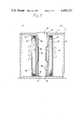
- FIG. 1is a cross-sectional view of a prior art induction heating furnace
- FIGS. 2 to 4are cross-sectional views of various embodiments of the instant induction heating furnace.
- FIG. 1depicts a prior art high temperature induction furnace generally referred to by the numeral 10.
- the furnace 10is comprised of a cylindrical housing 12 having a side wall 14, a top portion 16 and a bottom portion 18.
- the top portion 16has a central opening 22 therein which is vertically aligned with an opening 24 in the bottom portion 18.
- Asilica beaker 26, open at the top 28has a circular aperture 32 in the bottom surface thereof which is axially aligned with the openings 22 and 24.
- a tubular susceptor 34is centrally located within the beaker 26.
- the annular volume between the inside surface of the beaker 26 and the outsidesurface of the susceptor 34is filled with a zirconium dioxide insulating grain 36.
- An RF induction coil 38of circular or rectangular cross section, connected to a power source (not shown) is mounted about the beaker 26.
- the housing 12may be fabricated of copper which is water cooled, or the like, which acts as a shield to reduce stray radio-frequency fields.
- the susceptor 34is 8 weight percent yttria stabilized zirconium dioxide, composition 1372 of Zircoa Company, Solon, Ohio.
- the low temperature resistivity of the zirconium dioxide susceptor 34(>10 4 ohm-cm at room temperature) is too high to directly couple to the alternating electromagnetic field of the activated RF coil 38. For this reason, the zirconium dioxide susceptor 34 is preheated by coupling to a carbon rod (not shown), axially inserted therein, at room temperature. Above 1000° C. the zirconium dioxide susceptor 34 begins to couple to the electromagnetic field, and by approximately 1400° C. the carbon rod can be withdrawn without thermally shockingthe susceptor.
- the temperature of the furnace 10is raised to the operatingtemperature in approximately 60 minutes.
- the temperature of the zirconium dioxide susceptor 34is monitored and controlled with an infrared pyrometer (not shown) to within ⁇ 2° C. of the desired set point.
- Fiber drawing temperatures normally usedare between 1900° C. and 2300° C. depending upon the size of the preform44 and the fiber drawing velocity. During operation at these temperatures typically 7 kilowatts of power are required for maintaining a steady stateoperation. Frequencies on the order of about 4 megahertz are required for efficient operation at those temperatures.
- the RF fielddoes not couple tothe high resistivity grain 36 which is large particle sized and coarse grained. Thus, the grain 36 acts as an insulator to maintain an elevated temperature within the susceptor 34 during operation.
- the grain 36is electrically fused zirconium dioxide (-8 to 14 mesh) manufactured by TAM Ceramics, Niagara Falls, N.Y.
- a solid, substantially cylindrical, silica, lightguide preform 44(shown in phantom) is axially inserted therein until a first end 46 thereof is positioned at a "hot zone" which is located centrally in the susceptor within the RF coil 38.
- the elevated temperatureheats the preform 44 to reflow a small volume 48 at the end thereof from which a lightguide fiber 52 is drawn.
- a portion of the consolidated soot coatingdiffuses into any microcracks in the susceptor 34 to (1) form a seal and (2) act as a bond. Additionally, avery thin layer of the consolidated soot remains on the surface of the susceptor 34 which substantially precludes particles from leaving that surface and undesirably attaching to the preform 44.
- any of the deposited, consolidated soot which leaves the surface of the susceptor 34will not affect the drawn fiber 52 in as much as both the preform 44 and the consolidated soot are the same material.
- FIG. 2depicts a furnace 10 having a susceptor 34 comprised of three stacked zirconium dioxide tubes 53--53 in which a silica soot 54 has been deposited on the inside surface of only the middle tube. Additionally, a zirconium dioxide cylinder 62 is positioned about and in spaced relation to the susceptor tubes 53--53 leaving a space 64 therebetween. The cylinder 62 is sufficiently less dense (e.g., 20 to 30% porosity) than the high density susceptor tubes 53--53 so as not to be inductively coupled to the electromagnetic field ofthe energized coil 38.
- the cylinder 62is comprised of calcium stabilized zirconium dioxide coarse grain composition #1247 manufactured by Zircoa Company, Solon, Ohio.
- the silica soot 54consolidates on the inside of the middle susceptor tube 53 as hereinbeforedescribed to prevent particulate zirconium dioxide from migrating onto the lightguide preform 44. Furthermore, the cylinder 62 acts as a barrier to any microscopic particulate from the grain 36 that might be otherwise drawn through larger, unsealed cracks in the susceptor tubes 53--53.
- the middle tube 53was coated witha porous silica soot 68 on the outside surface in addition to the soot 54 on the inside surface thereof.
- the soot 68is also deposited on the outside surface only of the top and bottom tubes 53--53.
- the distance between the outer surface of the susceptor tubes 34--34 and the inner surface of the cylinder 62is not to scale and is exaggerated for purposesof clarity of exposition.
- the coils 38are energized to bring the furnace 10 up to temperature and the silica soot 54 and 68 consolidates on both sides of the middle susceptor tube 53.
- the glass soot 68 on the outside surface of the top and bottom tubes 53--53remains unconsolidated and tends to maintain a concentric alignment between the susceptor tubes 53--53 and the cylinder 62.
- the silica soot 68was deposited on the inside surface of the cylinder 62 and snugly slipped about the susceptor tubes 53--53.
- the middle tube 53was coated with silica soot 54 on the inside surface thereof.
- the soot 54is consolidated and a portion of the silica soot 68 consolidated on the central, inside surface of the cylinder 62 while the rest of the soot remains porous or unconsolidated to maintain the spaced, concentric alignment between the susceptor tubes 53--53 and the cylinder 62.
Landscapes
- Engineering & Computer Science (AREA)
- Chemical & Material Sciences (AREA)
- Life Sciences & Earth Sciences (AREA)
- General Life Sciences & Earth Sciences (AREA)
- Geochemistry & Mineralogy (AREA)
- Manufacturing & Machinery (AREA)
- Materials Engineering (AREA)
- Organic Chemistry (AREA)
- General Induction Heating (AREA)
- Furnace Details (AREA)
Abstract
Description
Claims (6)
Priority Applications (7)
| Application Number | Priority Date | Filing Date | Title |
|---|---|---|---|
| US06/383,386US4450333A (en) | 1982-05-28 | 1982-05-28 | Zirconia induction furnace |
| DE8383901557TDE3369452D1 (en) | 1982-05-28 | 1983-04-11 | Modified zirconia induction furnace |
| PCT/US1983/000512WO1983004364A1 (en) | 1982-05-28 | 1983-04-11 | Modified zirconia induction furnace |
| EP83901557AEP0110899B1 (en) | 1982-05-28 | 1983-04-11 | Modified zirconia induction furnace |
| CA000426827ACA1187290A (en) | 1982-05-28 | 1983-04-27 | Zirconia induction furnace |
| IT21323/83AIT1171073B (en) | 1982-05-28 | 1983-05-26 | PROCEDURE AND INDUCTION OVEN MODIFIED IN ZIRCONIA |
| GB08314808AGB2121028B (en) | 1982-05-28 | 1983-05-27 | Induction furnace for drawing lightguide fibres from preforms |
Applications Claiming Priority (1)
| Application Number | Priority Date | Filing Date | Title |
|---|---|---|---|
| US06/383,386US4450333A (en) | 1982-05-28 | 1982-05-28 | Zirconia induction furnace |
Publications (1)
| Publication Number | Publication Date |
|---|---|
| US4450333Atrue US4450333A (en) | 1984-05-22 |
Family
ID=23512891
Family Applications (1)
| Application Number | Title | Priority Date | Filing Date |
|---|---|---|---|
| US06/383,386Expired - LifetimeUS4450333A (en) | 1982-05-28 | 1982-05-28 | Zirconia induction furnace |
Country Status (2)
| Country | Link |
|---|---|
| US (1) | US4450333A (en) |
| CA (1) | CA1187290A (en) |
Cited By (26)
| Publication number | Priority date | Publication date | Assignee | Title |
|---|---|---|---|---|
| US4533378A (en)* | 1982-05-28 | 1985-08-06 | At&T Technologies, Inc. | Modified zirconia induction furnace |
| US4547644A (en)* | 1984-02-24 | 1985-10-15 | At&T Technologies, Inc. | Apparatus for heating a preform from which lightguide fiber is drawn |
| US4608473A (en)* | 1982-05-28 | 1986-08-26 | At&T Technologies, Inc. | Modified zirconia induction furnace |
| US4748307A (en)* | 1985-05-04 | 1988-05-31 | Stc Plc | Tube furnace |
| US4857092A (en)* | 1984-11-07 | 1989-08-15 | U.S. Philips Corp. | Method of densifying a preformed porous body of a material the main constituent of which is SiO2 |
| US4952226A (en)* | 1989-02-27 | 1990-08-28 | American Telephone And Telegraph Company | Lightguide coating control |
| US4973349A (en)* | 1989-01-04 | 1990-11-27 | Selas S.A. | Chamber for the thermal treatment of objects |
| US5039325A (en)* | 1990-01-02 | 1991-08-13 | At&T Bell Laboratories | Method for consolidating doped glass using an encapsulating structure |
| US5076824A (en)* | 1990-05-14 | 1991-12-31 | At&T Bell Laboratories | Method of making fiber optical preform with pyrolytic coated mandrel |
| US5106401A (en)* | 1989-06-29 | 1992-04-21 | Sumitomo Electric Industries, Ltd. | Process for thermal treatment of glass fiber preform |
| US5134261A (en)* | 1990-03-30 | 1992-07-28 | The United States Of America As Represented By The Secretary Of The Air Force | Apparatus and method for controlling gradients in radio frequency heating |
| US5199966A (en)* | 1988-04-29 | 1993-04-06 | At&T Bell Laboratories | Optical coupler method |
| US5228893A (en)* | 1991-11-27 | 1993-07-20 | At&T Bell Laboratories | Optical fiber tension monitoring technique |
| US5308947A (en)* | 1992-01-30 | 1994-05-03 | At&T Bell Laboratories | Iridium fiber draw induction furnace |
| US5410567A (en)* | 1992-03-05 | 1995-04-25 | Corning Incorporated | Optical fiber draw furnace |
| US5698124A (en)* | 1995-05-18 | 1997-12-16 | Lucent Technologies Inc. | Magnesia fiber draw furnace |
| US5713979A (en)* | 1992-05-14 | 1998-02-03 | Tsl Group Plc | Heat treatment facility for synthetic vitreous silica bodies |
| US6260386B1 (en) | 1994-03-10 | 2001-07-17 | Lucent Technologies Inc. | Optical fiber preform cleaning method |
| US6326063B1 (en)* | 1998-01-29 | 2001-12-04 | Tocalo Co., Ltd. | Method of production of self-fusing alloy spray coating member |
| US6354113B2 (en) | 1999-01-20 | 2002-03-12 | Alcatel | Fiber optic draw furnace featuring a fiber optic preform heating and fiber drawing programmable logic controller |
| US20020088253A1 (en)* | 1999-05-10 | 2002-07-11 | Roba Giacomo Stefano | Method and induction furnace for drawing large diameter preforms to optical fibres |
| US20020144523A1 (en)* | 2001-04-04 | 2002-10-10 | The Furukawa Electric Co., Ltd. | Optical fiber drawing furnace |
| US20060130524A1 (en)* | 2002-12-05 | 2006-06-22 | Nextrom Holding S.A. | Method and apparatus for making optical fibres |
| US20110052460A1 (en)* | 2006-08-10 | 2011-03-03 | Calvin Thomas Coffey | Apparatus for particle synthesis |
| US20180084609A1 (en)* | 2016-09-19 | 2018-03-22 | Corning Incorporated | Millimeter wave heating of soot preform |
| AT521245A4 (en)* | 2018-08-28 | 2019-12-15 | Ib Eng Gmbh | furnace |
Citations (11)
| Publication number | Priority date | Publication date | Assignee | Title |
|---|---|---|---|---|
| US3362803A (en)* | 1964-03-05 | 1968-01-09 | Fed Republic Of Germany | Method of making glass or ceramic covered wires |
| US3401227A (en)* | 1966-02-09 | 1968-09-10 | Trw Inc | Liner for crucibles |
| US3404973A (en)* | 1963-03-05 | 1968-10-08 | Saint Gobain | Glass sheet forming apparatus with coated silica core roller and roller |
| FR2013820A1 (en)* | 1968-07-26 | 1970-04-10 | Siemens Ag | |
| US3916047A (en)* | 1973-08-21 | 1975-10-28 | Raymond J Niesen | Coated steel form for use in a coreless induction furnace |
| US4029466A (en)* | 1974-08-08 | 1977-06-14 | Denki Kagaku Kogyo Kabushiki Kaisha | Container for evaporation of metal |
| US4052153A (en)* | 1975-03-06 | 1977-10-04 | Prolizenz Ag | Heat resistant crucible |
| US4090851A (en)* | 1976-10-15 | 1978-05-23 | Rca Corporation | Si3 N4 Coated crucible and die means for growing single crystalline silicon sheets |
| US4107450A (en)* | 1974-06-10 | 1978-08-15 | Owens-Corning Fiberglas Corporation | Refractories and methods of making same |
| US4159891A (en)* | 1975-03-12 | 1979-07-03 | Prolizenz Ag | Crucible |
| US4356152A (en)* | 1981-03-13 | 1982-10-26 | Rca Corporation | Silicon melting crucible |
- 1982
- 1982-05-28USUS06/383,386patent/US4450333A/ennot_activeExpired - Lifetime
- 1983
- 1983-04-27CACA000426827Apatent/CA1187290A/ennot_activeExpired
Patent Citations (11)
| Publication number | Priority date | Publication date | Assignee | Title |
|---|---|---|---|---|
| US3404973A (en)* | 1963-03-05 | 1968-10-08 | Saint Gobain | Glass sheet forming apparatus with coated silica core roller and roller |
| US3362803A (en)* | 1964-03-05 | 1968-01-09 | Fed Republic Of Germany | Method of making glass or ceramic covered wires |
| US3401227A (en)* | 1966-02-09 | 1968-09-10 | Trw Inc | Liner for crucibles |
| FR2013820A1 (en)* | 1968-07-26 | 1970-04-10 | Siemens Ag | |
| US3916047A (en)* | 1973-08-21 | 1975-10-28 | Raymond J Niesen | Coated steel form for use in a coreless induction furnace |
| US4107450A (en)* | 1974-06-10 | 1978-08-15 | Owens-Corning Fiberglas Corporation | Refractories and methods of making same |
| US4029466A (en)* | 1974-08-08 | 1977-06-14 | Denki Kagaku Kogyo Kabushiki Kaisha | Container for evaporation of metal |
| US4052153A (en)* | 1975-03-06 | 1977-10-04 | Prolizenz Ag | Heat resistant crucible |
| US4159891A (en)* | 1975-03-12 | 1979-07-03 | Prolizenz Ag | Crucible |
| US4090851A (en)* | 1976-10-15 | 1978-05-23 | Rca Corporation | Si3 N4 Coated crucible and die means for growing single crystalline silicon sheets |
| US4356152A (en)* | 1981-03-13 | 1982-10-26 | Rca Corporation | Silicon melting crucible |
Non-Patent Citations (2)
| Title |
|---|
| "A Zirconia Induction Furnace for Drawing Precision Silica Wave Guides", by R. B. Runk, Optical Fiber Transmission II Technical Digest (Tu B5-1), Feb. 1977. |
| A Zirconia Induction Furnace for Drawing Precision Silica Wave Guides , by R. B. Runk, Optical Fiber Transmission II Technical Digest (Tu B5 1), Feb. 1977.* |
Cited By (31)
| Publication number | Priority date | Publication date | Assignee | Title |
|---|---|---|---|---|
| US4533378A (en)* | 1982-05-28 | 1985-08-06 | At&T Technologies, Inc. | Modified zirconia induction furnace |
| US4608473A (en)* | 1982-05-28 | 1986-08-26 | At&T Technologies, Inc. | Modified zirconia induction furnace |
| US4547644A (en)* | 1984-02-24 | 1985-10-15 | At&T Technologies, Inc. | Apparatus for heating a preform from which lightguide fiber is drawn |
| US4857092A (en)* | 1984-11-07 | 1989-08-15 | U.S. Philips Corp. | Method of densifying a preformed porous body of a material the main constituent of which is SiO2 |
| US4748307A (en)* | 1985-05-04 | 1988-05-31 | Stc Plc | Tube furnace |
| US5199966A (en)* | 1988-04-29 | 1993-04-06 | At&T Bell Laboratories | Optical coupler method |
| US4973349A (en)* | 1989-01-04 | 1990-11-27 | Selas S.A. | Chamber for the thermal treatment of objects |
| US4952226A (en)* | 1989-02-27 | 1990-08-28 | American Telephone And Telegraph Company | Lightguide coating control |
| US5106401A (en)* | 1989-06-29 | 1992-04-21 | Sumitomo Electric Industries, Ltd. | Process for thermal treatment of glass fiber preform |
| US5039325A (en)* | 1990-01-02 | 1991-08-13 | At&T Bell Laboratories | Method for consolidating doped glass using an encapsulating structure |
| US5134261A (en)* | 1990-03-30 | 1992-07-28 | The United States Of America As Represented By The Secretary Of The Air Force | Apparatus and method for controlling gradients in radio frequency heating |
| US5076824A (en)* | 1990-05-14 | 1991-12-31 | At&T Bell Laboratories | Method of making fiber optical preform with pyrolytic coated mandrel |
| US5316562A (en)* | 1991-11-27 | 1994-05-31 | At&T Bell Laboratories | Optical fiber tension monitoring technique |
| US5228893A (en)* | 1991-11-27 | 1993-07-20 | At&T Bell Laboratories | Optical fiber tension monitoring technique |
| US5308947A (en)* | 1992-01-30 | 1994-05-03 | At&T Bell Laboratories | Iridium fiber draw induction furnace |
| US5410567A (en)* | 1992-03-05 | 1995-04-25 | Corning Incorporated | Optical fiber draw furnace |
| US5713979A (en)* | 1992-05-14 | 1998-02-03 | Tsl Group Plc | Heat treatment facility for synthetic vitreous silica bodies |
| US6260386B1 (en) | 1994-03-10 | 2001-07-17 | Lucent Technologies Inc. | Optical fiber preform cleaning method |
| US5698124A (en)* | 1995-05-18 | 1997-12-16 | Lucent Technologies Inc. | Magnesia fiber draw furnace |
| US6326063B1 (en)* | 1998-01-29 | 2001-12-04 | Tocalo Co., Ltd. | Method of production of self-fusing alloy spray coating member |
| US6354113B2 (en) | 1999-01-20 | 2002-03-12 | Alcatel | Fiber optic draw furnace featuring a fiber optic preform heating and fiber drawing programmable logic controller |
| US20020088253A1 (en)* | 1999-05-10 | 2002-07-11 | Roba Giacomo Stefano | Method and induction furnace for drawing large diameter preforms to optical fibres |
| US7814767B2 (en) | 1999-05-10 | 2010-10-19 | Prysmian Cavi E Sistemi Energia S.R.L. | Method and induction furnace for drawing large diameter preforms to optical fibres |
| US20020144523A1 (en)* | 2001-04-04 | 2002-10-10 | The Furukawa Electric Co., Ltd. | Optical fiber drawing furnace |
| US20060130524A1 (en)* | 2002-12-05 | 2006-06-22 | Nextrom Holding S.A. | Method and apparatus for making optical fibres |
| US20110052460A1 (en)* | 2006-08-10 | 2011-03-03 | Calvin Thomas Coffey | Apparatus for particle synthesis |
| US8362407B2 (en)* | 2006-08-10 | 2013-01-29 | Corning Incorporated | Apparatus for particle synthesis |
| US20180084609A1 (en)* | 2016-09-19 | 2018-03-22 | Corning Incorporated | Millimeter wave heating of soot preform |
| US10893577B2 (en)* | 2016-09-19 | 2021-01-12 | Corning Incorporated | Millimeter wave heating of soot preform |
| AT521245A4 (en)* | 2018-08-28 | 2019-12-15 | Ib Eng Gmbh | furnace |
| AT521245B1 (en)* | 2018-08-28 | 2019-12-15 | Ib Eng Gmbh | furnace |
Also Published As
| Publication number | Publication date |
|---|---|
| CA1187290A (en) | 1985-05-21 |
Similar Documents
| Publication | Publication Date | Title |
|---|---|---|
| US4450333A (en) | Zirconia induction furnace | |
| US4547644A (en) | Apparatus for heating a preform from which lightguide fiber is drawn | |
| US4608473A (en) | Modified zirconia induction furnace | |
| CA1212837A (en) | Method of and device for the continuous manufacture of elongate bodies starting from unmolten solid starting material | |
| EP1181255B1 (en) | Method and induction furnace for drawing large diameter preforms to optical fibres | |
| EP0110899B1 (en) | Modified zirconia induction furnace | |
| US4533378A (en) | Modified zirconia induction furnace | |
| JPS593036A (en) | Method and apparatus for manufacturing optical preforms using chemical vapor phase axising method | |
| CA1101164A (en) | Method and apparatus for producing fibers for optical transmission | |
| US5685889A (en) | Method for flame abrasion of glass preform | |
| US5545246A (en) | Method and device for manufacturing an optical fiber | |
| CA2083858C (en) | Iridium fiber draw induction furnace | |
| AU552580B2 (en) | Digital concentrator | |
| GB1521231A (en) | Induction furnace | |
| US4761170A (en) | Method for employing plasma in dehydration and consolidation of preforms | |
| US5698124A (en) | Magnesia fiber draw furnace | |
| Runk | A zirconia induction furnace for drawing precision silica wave guides | |
| US4748307A (en) | Tube furnace | |
| EP0743289B1 (en) | Zirconia induction furnace having magnesia insulation for drawing glass optical fibers | |
| JPH0455984B2 (en) | ||
| US6658897B2 (en) | Optical fiber draw furnace having a SiC or Silicon Nitride tube | |
| EP0112549B1 (en) | Improved sintering of optical fiber preforms | |
| AU734347B2 (en) | Apparatus and method for drawing waveguide fibers | |
| GB2192698A (en) | Tube furnace | |
| EP1461293B1 (en) | A method and a device in the manufacture of an optical fibre |
Legal Events
| Date | Code | Title | Description |
|---|---|---|---|
| AS | Assignment | Owner name:WESTERN ELECTRIC COMPANY, INCORPORATED 222 BROADWA Free format text:ASSIGNMENT OF ASSIGNORS INTEREST.;ASSIGNORS:ANDREJCO, MATTHEW J.;PAEK, UN C.;SCHROEDER, CHARLES M. JR.;REEL/FRAME:003997/0686 Effective date:19820526 | |
| AS | Assignment | Owner name:AT & T TECHNOLOGIES, INC., Free format text:CHANGE OF NAME;ASSIGNOR:WESTERN ELECTRIC COMPANY, INCORPORATED;REEL/FRAME:004251/0868 Effective date:19831229 | |
| STCF | Information on status: patent grant | Free format text:PATENTED CASE | |
| FEPP | Fee payment procedure | Free format text:PAYOR NUMBER ASSIGNED (ORIGINAL EVENT CODE: ASPN); ENTITY STATUS OF PATENT OWNER: LARGE ENTITY | |
| FPAY | Fee payment | Year of fee payment:4 | |
| FPAY | Fee payment | Year of fee payment:8 | |
| FPAY | Fee payment | Year of fee payment:12 | |
| AS | Assignment | Owner name:LUCENT TECHNOLOGIES INC., NEW JERSEY Free format text:ASSIGNMENT OF ASSIGNORS INTEREST;ASSIGNOR:AT&T CORP.;REEL/FRAME:012059/0893 Effective date:19960329 | |
| AS | Assignment | Owner name:FITEL USA CORPORATION, GEORGIA Free format text:ASSIGNMENT OF ASSIGNORS INTEREST;ASSIGNOR:LUCENT TECHNOLOGIES;REEL/FRAME:012946/0578 Effective date:20011116 |