US4447234A - Medication infusion pump - Google Patents
Medication infusion pumpDownload PDFInfo
- Publication number
- US4447234A US4447234AUS06/403,999US40399982AUS4447234AUS 4447234 AUS4447234 AUS 4447234AUS 40399982 AUS40399982 AUS 40399982AUS 4447234 AUS4447234 AUS 4447234A
- Authority
- US
- United States
- Prior art keywords
- compartment
- disposable portion
- disposable
- solenoid
- armature
- Prior art date
- Legal status (The legal status is an assumption and is not a legal conclusion. Google has not performed a legal analysis and makes no representation as to the accuracy of the status listed.)
- Expired - Lifetime
Links
Images


Classifications
- A—HUMAN NECESSITIES
- A61—MEDICAL OR VETERINARY SCIENCE; HYGIENE
- A61M—DEVICES FOR INTRODUCING MEDIA INTO, OR ONTO, THE BODY; DEVICES FOR TRANSDUCING BODY MEDIA OR FOR TAKING MEDIA FROM THE BODY; DEVICES FOR PRODUCING OR ENDING SLEEP OR STUPOR
- A61M5/00—Devices for bringing media into the body in a subcutaneous, intra-vascular or intramuscular way; Accessories therefor, e.g. filling or cleaning devices, arm-rests
- A61M5/14—Infusion devices, e.g. infusing by gravity; Blood infusion; Accessories therefor
- A61M5/142—Pressure infusion, e.g. using pumps
- A61M5/14244—Pressure infusion, e.g. using pumps adapted to be carried by the patient, e.g. portable on the body
- Y—GENERAL TAGGING OF NEW TECHNOLOGICAL DEVELOPMENTS; GENERAL TAGGING OF CROSS-SECTIONAL TECHNOLOGIES SPANNING OVER SEVERAL SECTIONS OF THE IPC; TECHNICAL SUBJECTS COVERED BY FORMER USPC CROSS-REFERENCE ART COLLECTIONS [XRACs] AND DIGESTS
- Y10—TECHNICAL SUBJECTS COVERED BY FORMER USPC
- Y10S—TECHNICAL SUBJECTS COVERED BY FORMER USPC CROSS-REFERENCE ART COLLECTIONS [XRACs] AND DIGESTS
- Y10S128/00—Surgery
- Y10S128/12—Pressure infusion
Definitions
- the present inventionrelates generally to medication infusion devices, and more particularly to a miniature extracorporeal medication infusion device for precisely and conveniently dispensing controlled quantities of a liquid medicine into a human or animal body.
- Liquid medications(which, for purposes of this patent application, means any liquid that is to be injected into a human or animal body for therapeutic or diagnostic purposes) have been traditionally administered by a hypodermic syringe. If multiple doses of the liquid medication are required, the multiple doses are typically administered at timed intervals of several days or several hours.
- the present inventiondeparts from these and other prior art devices by providing an extracorporeal medication infusion device which permits precise control of the dosage of liquid medication that is administered and that provides ease and convenience of use.
- the extracorporeal medication infusion deviceincludes a reusable portion and a disposable portion.
- the reusable portionincludes a rigid case, a battery power supply, and a programmable electronic controller.
- the reusable portion of the infusion devicealso includes an electromagnetic solenoid core and an electromagnetic solenoid coil which receives an electrical signal from the controller and provides a magnetic actuating force.
- the disposable portion of the infusion deviceincludes a collapsable reservoir for storing the liquid medication.
- the disposable portionalso includes a disposable pump for pumping the liquid medication from the reservoir to the human or animal body to which the liquid medication is to be provided.
- the pumpincludes a pumping chamber having inlet and outlet check valves, and an electromagnetic armature provides a means to vary the volume of the chamber in response to the magnetic actuating force of the coil.
- the disposable portion and the reusable portioneach also include precise alignment surfaces arranged in predetermined positions.
- the alignment surfaces of the disposable portionengage corresponding alignment surfaces of the resuable portion.
- the armature on the disposable portionis precisely aligned with and spaced a predetermined distance from the core in the reusable portion.
- This arrangment of applicant's inventionassures that the movement of the armature and corresponding stroke of the pump will always be the same, when the disposable portions are changed on a periodic basis while the device is being used. Additionally, because the pump utilizes the positive action of a leaf spring to return the pump to the rest position at the completion of each pump cycle, the return stroke and output pressure of the pump is also precisely controlled. Still further, the infusion device provided by the instant invention is convenient and easy to use, and provides the option to the user of either filling the reservoir pump from a separate vial of liquid medication or purchasing the disposable portion in a prefilled condition for maximum convenience and ease of use.
- FIG. 1is a perspective view of the extracorporeal medication infusion device according to the principles of the invention
- FIG. 2is a perspective view of the disposable portion of the device shown in FIG. 1;
- FIG. 3is an enlarged cross-sectional view taken along reference view line 3--3 in FIG. 2;
- FIG. 4is a cross-sectional view taken along reference view line 4--4 in FIG. 1;
- FIG. 5is a perspective view of a spring that is used to maintain alignment of the disposable portion and the reusable portion of the device shown in FIG. 1;
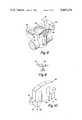
- FIG. 6is an enlarged view of the inlet check valve shown in FIG. 3;
- FIG. 7is a still further enlarged perspective view of the check valve shown in FIG. 6;
- FIG. 8is an enlarged perspective view of the pump housing for the device, with the armature shown in phantom;
- FIG. 9is a side-elevational view of the armature for the disposable portion shown in FIG. 2;
- FIG. 10is an enlarged perspective view of the solenoid core for the reusable portion of the device shown in FIG. 4.
- FIG. 1illustrates an extracorporeal medication infusion device 10.
- the medication infusion device 10is of small size (approximately 21/2 inches long, 1 inch wide, and 1/2 inch thick) and light weight (approximately 21/2 ounces) and is adapted to be carried in the user's pocket or taped or strapped to the user's body.
- the medication infusion device 10as explained in further detail below, carries a reservoir of liquid medication and provides a means for dispensing the liquid medication into the user's body at a programmed rate.
- the medication infusion device 10includes a reusable portion 11 and a disposable portion 12.
- the reusable portion 11is adapted to be utilized repeatedly over a period of several years for dispensing liquid medication to the body of the user.
- the disposable portion 12is adapted to dispense a predetermined quantity of liquid medication which it carries, and to then be discarded and replaced with a new disposable portion carrying a new quantity of the liquid medication.
- the reusable portion 11includes a rigid plastic case 15.
- the case 15includes a top wall 16, a bottom wall 17, end walls 18, and internal dividing walls 19.
- the walls 16-19are all of approximately the same thickness and same material.
- the top wall 16includes a removable panel 20 for providing access to the disposable portion 12 and a removable panel 21 for providing access to a battery 22 which provides a source of electrical power for the medication infusion device 10.
- the removable panels 20 and 21are secured in place by a suitable detent (not shown) in a well known manner.
- the reusable portion 11also includes a programmable electronic controller 23 which receives electrical power from the battery 22 and which provides electrical energy to a solenoid 24.
- the solenoid 24includes a coil 25 which is energized by the controller 23 on a programmed basis and an electromagnetic core 26.
- the core 26, as shown in greater detail in FIG. 10,is made of magnetic material (such as a martensitic stainless steel) and is of a generally E-shaped configuration.
- the core 26includes end walls 27, 28 and 29 which face toward an armature as explained in greater detail below.
- the end walls 27 and 29are coplanar, and the end wall 28 may be recessed slightly from the plane in which the walls 27 and 29 are disposed to facilitate release of the armature after actuation of the coil 25.
- the alignment bars 30are each of non-magnetic material (such as an austenitic stainless steel) and are welded to the core 26 in the position shown in FIG. 10.
- the alignment bars 30each include a precise alignment surface 31, and the alignment surfaces 31 are co-planar.
- the plane in which the alignment surfaces 31 are disposedis spaced a predetermined distance from the plane in which the core surfaces 27 and 29 are disposed, and the perpendicular distance between these two planes is the stroke of the pump, as explained in further detail below.
- the medication infusion device 10also includes a replaceable needle and connecting tube assembly 34.
- the assembly 34is connected to the disposable portion 12 by a threaded connection 35.
- the needle and connecting tube assembly 34may therefore be disconnected from the disposable portion 12 when the disposable portion 12 is to be replaced.
- the disposable portion 12includes a reservoir 41, a pump 42, and an electromagnetic armature 43.
- the reservoir 41includes a collapsable plastic bag 44 that is secured within a cylindrical plastic housing 45 and sealingly attached to a plastic end wall 46.
- the collapsable bag 44is filled by injecting the liquid medicine that is to be dispensed through a septum 47.
- the pump 42includes a pump housing 49 which defines an inlet passage 50, an outlet passage 51, and a pump chamber 52.
- the pump 42also includes check valves 53 placed in the inlet and outlet passages 50 and 51.
- the check valves 53are of one-piece plastic construction and include a base 54.
- the check valvesare of a thermoplastic carbonate linked polymer such as that sold under the trademark "Lexan” by General Electric Co., or of an acrylic polymer resin such as that sold under the trademark "Cryolite G-20" by Cry/Ro Industries.
- An annular seat 55projects from one side of the base 54 to provide sealing engagement with an adjacent surface in the passage.
- a plurality of leaf spring portions 56projects from a central hub of the base 54 and provide a spring force to urge the seat 55 against its adjacent surface.
- a plurality of axially extending stops 57which are disposed between adjacent ones of the springs 56, project from the base 54 in a direction opposite to the seat 55 to control the travel of the seat 55 away from its adjacent surface when the check valve 53 is opened.
- the pump 42further includes a piston 61 which reciprocates in a bore that intersects the pump chamber 52 in a direction perpendicular to the axis of the passages 50 and 51.
- the piston 61is of plastic construction and is sealed against the walls of the bore in which it is dispersed by an o-ring seal 62.
- the o-ring seal 62is dimensioned and arranged so that it is compressed in the groove in the outer peripheral surface of the piston 61 and so that it does not slide relative to either the piston 61 or the bore. Instead, the o-ring 62 is of sufficient elasticity, and the movement of the piston 61 is sufficiently small, that elastic deformation of the o-ring 62 is sufficient to accommodate the full stroke of the piston 61 in the bore.
- the electromagnetic armature 43which is of magnetic material such as martensitic stainless steel, includes a stem portion projecting from its bottom surface which is received with an interference fit in a bore in the piston 61. In this manner, the armature 43 is rigidly connected to the piston 61 so that movement of the armature 43 causes corresponding movement of the piston 61.
- Two suitable spring rests 63project laterally in opposite directions from the aramture 43.
- Two identical leaf springs 64are provided on each lateral side of the pump housing 49 and act between the pump housing 49 and the spring rests 63 to urge the piston 61 to its rest position shown in the drawings.
- the pump housing 49also includes alignment surfaces 67.
- the alignment surfaces 67are co-planar with one another and are co-planar with the top surface of the armature 43.
- this co-planar relationshipmay be accomplished by initially making the alignment surfaces 67 project beyond the top surface of the armature 43, and then, after the armature 43 and springs 64 are installed in the pump housing 49, melting or grinding the surfaces 67 to a co-planar relationship with the top surface of the armature 43.
- the disposable portion 12is releasably assembled in the case 15 by opening th removable panel 20.
- the disposable portion 12is then inserted into the case 15 in a manner such that the alignment surfaces 67 of the pump housing 49 (FIG. 8) contact the alignment surfaces 31 of the core 26 (FIG. 10). This contact is established and maintained by a suitable leaf spring 68 (see FIGS. 4 and 5).
- An elastomeric grommet 69which is frictionally received in an open ended slot in the case 15 when the cover 20 is removed, secures the removable portion 12 against axial movement relative to the reusable portion 11.
- the materials for the reusable portion 11 and disposable portion 12are selected from commercially available thermoplastic materials to provide adequate strength and rigidity, resistance to chemicals, and ease of manufacturing.
- the case 15is of an acrylonitrile-butadiene-styrene copolymer (ABS)
- the reservoir 44is of a suitable flexible thermoplastic urethane resin
- the pump housing 49 and piston 61are of an acrylic polymer resin such as that sold under the trademark "Cryolite G-20" by Cy/Ro Industries.
- the controller 23When it is desired to pump the liquid medication from the collapsable reservoir 44 to the outlet passage 51 and to the needle and tube assembly 34, the controller 23 provides an electrical current to energize the coil 25. This causes the armature 43 to move upwardly as viewed in the drawings until the top surface of the armature 43 engages the surfaces 27 and 29 of the core 26. This causes the piston 61 to move upwardly to increase the volume of the chamber 52. As the volume of the chamber 52 increases, the check valve 53 in the inlet passage 50 opens to permit liquid medication to flow from the reservoir 44 into the pump chamber 52. When this electrical current is interrupted, the coil 25 is de-energized and the springs 64 push the armature 43 and piston 61 downwardly as viewed in the drawings to decrease the volume of the chamber 52.
Landscapes
- Health & Medical Sciences (AREA)
- Vascular Medicine (AREA)
- Engineering & Computer Science (AREA)
- Anesthesiology (AREA)
- Biomedical Technology (AREA)
- Heart & Thoracic Surgery (AREA)
- Hematology (AREA)
- Life Sciences & Earth Sciences (AREA)
- Animal Behavior & Ethology (AREA)
- General Health & Medical Sciences (AREA)
- Public Health (AREA)
- Veterinary Medicine (AREA)
- Infusion, Injection, And Reservoir Apparatuses (AREA)
Abstract
Description
Claims (5)
Priority Applications (1)
| Application Number | Priority Date | Filing Date | Title |
|---|---|---|---|
| US06/403,999US4447234A (en) | 1981-04-10 | 1982-08-02 | Medication infusion pump |
Applications Claiming Priority (2)
| Application Number | Priority Date | Filing Date | Title |
|---|---|---|---|
| US25277981A | 1981-04-10 | 1981-04-10 | |
| US06/403,999US4447234A (en) | 1981-04-10 | 1982-08-02 | Medication infusion pump |
Related Parent Applications (1)
| Application Number | Title | Priority Date | Filing Date |
|---|---|---|---|
| US25277981ADivision | 1981-04-10 | 1981-04-10 |
Publications (1)
| Publication Number | Publication Date |
|---|---|
| US4447234Atrue US4447234A (en) | 1984-05-08 |
Family
ID=26942647
Family Applications (1)
| Application Number | Title | Priority Date | Filing Date |
|---|---|---|---|
| US06/403,999Expired - LifetimeUS4447234A (en) | 1981-04-10 | 1982-08-02 | Medication infusion pump |
Country Status (1)
| Country | Link |
|---|---|
| US (1) | US4447234A (en) |
Cited By (14)
| Publication number | Priority date | Publication date | Assignee | Title |
|---|---|---|---|---|
| US4487603A (en)* | 1982-11-26 | 1984-12-11 | Cordis Corporation | Implantable microinfusion pump system |
| USH150H (en) | 1984-08-03 | 1986-11-04 | Medtronic, Inc. | Accessory module for implantable fluid dispensing device |
| US5009641A (en)* | 1988-12-02 | 1991-04-23 | Pacesetter Infusion, Ltd. | Patient-controlled analgesia security attachment for a medication infusion system |
| US5558639A (en)* | 1993-06-10 | 1996-09-24 | Gangemi; Ronald J. | Ambulatory patient infusion apparatus |
| US5951512A (en)* | 1996-05-28 | 1999-09-14 | Horizon Medical Products, Inc. | Infusion port with modified drug reservoir |
| US20070073250A1 (en)* | 2005-07-08 | 2007-03-29 | Schneiter James A | Implantable port |
| US20080097375A1 (en)* | 2006-08-23 | 2008-04-24 | Medtronic Minimed, Inc. | Infusion pumps and methods and delivery devices and methods with same |
| EP2076298A1 (en)* | 2006-10-07 | 2009-07-08 | Sanofi-Aventis Deutschland GmbH | Micropump-operated drug dosing system |
| US8105269B2 (en) | 2008-10-24 | 2012-01-31 | Baxter International Inc. | In situ tubing measurements for infusion pumps |
| US8137083B2 (en) | 2009-03-11 | 2012-03-20 | Baxter International Inc. | Infusion pump actuators, system and method for controlling medical fluid flowrate |
| US20120209186A1 (en)* | 2006-02-09 | 2012-08-16 | Dean Kamen | Patch-sized fluid delivery systems and methods |
| US8382447B2 (en) | 2009-12-31 | 2013-02-26 | Baxter International, Inc. | Shuttle pump with controlled geometry |
| US8567235B2 (en) | 2010-06-29 | 2013-10-29 | Baxter International Inc. | Tube measurement technique using linear actuator and pressure sensor |
| US8955532B2 (en) | 2009-09-18 | 2015-02-17 | Fluid Automation Systems S.A | Valve with a removable cartridge |
Citations (3)
| Publication number | Priority date | Publication date | Assignee | Title |
|---|---|---|---|---|
| US3051173A (en)* | 1960-05-12 | 1962-08-28 | Alvin P Johnson | Veterinary hypodermic syringe |
| US4274407A (en)* | 1979-11-13 | 1981-06-23 | Med Pump, Inc. | Fluid injection system |
| US4397639A (en)* | 1980-04-24 | 1983-08-09 | Ferring Arzneimittel Gmbh | Device for the intermittent pulsatory application of fluid medicaments |
- 1982
- 1982-08-02USUS06/403,999patent/US4447234A/ennot_activeExpired - Lifetime
Patent Citations (3)
| Publication number | Priority date | Publication date | Assignee | Title |
|---|---|---|---|---|
| US3051173A (en)* | 1960-05-12 | 1962-08-28 | Alvin P Johnson | Veterinary hypodermic syringe |
| US4274407A (en)* | 1979-11-13 | 1981-06-23 | Med Pump, Inc. | Fluid injection system |
| US4397639A (en)* | 1980-04-24 | 1983-08-09 | Ferring Arzneimittel Gmbh | Device for the intermittent pulsatory application of fluid medicaments |
Cited By (18)
| Publication number | Priority date | Publication date | Assignee | Title |
|---|---|---|---|---|
| US4487603A (en)* | 1982-11-26 | 1984-12-11 | Cordis Corporation | Implantable microinfusion pump system |
| USH150H (en) | 1984-08-03 | 1986-11-04 | Medtronic, Inc. | Accessory module for implantable fluid dispensing device |
| US5009641A (en)* | 1988-12-02 | 1991-04-23 | Pacesetter Infusion, Ltd. | Patient-controlled analgesia security attachment for a medication infusion system |
| US5558639A (en)* | 1993-06-10 | 1996-09-24 | Gangemi; Ronald J. | Ambulatory patient infusion apparatus |
| US5951512A (en)* | 1996-05-28 | 1999-09-14 | Horizon Medical Products, Inc. | Infusion port with modified drug reservoir |
| US20070073250A1 (en)* | 2005-07-08 | 2007-03-29 | Schneiter James A | Implantable port |
| US20140207067A1 (en)* | 2006-02-09 | 2014-07-24 | Deka Products Limited Partnership | Adhesive and Peripheral Systems and Methods for Medical Devices |
| US10639418B2 (en)* | 2006-02-09 | 2020-05-05 | Deka Products Limited Partnership | Patch-sized fluid delivery systems and methods |
| US20120209186A1 (en)* | 2006-02-09 | 2012-08-16 | Dean Kamen | Patch-sized fluid delivery systems and methods |
| US20080097375A1 (en)* | 2006-08-23 | 2008-04-24 | Medtronic Minimed, Inc. | Infusion pumps and methods and delivery devices and methods with same |
| US8187228B2 (en)* | 2006-08-23 | 2012-05-29 | Medtronic Minimed, Inc. | Infusion pumps and methods and delivery devices and methods with same |
| EP2076298A1 (en)* | 2006-10-07 | 2009-07-08 | Sanofi-Aventis Deutschland GmbH | Micropump-operated drug dosing system |
| US8105269B2 (en) | 2008-10-24 | 2012-01-31 | Baxter International Inc. | In situ tubing measurements for infusion pumps |
| US8496613B2 (en) | 2008-10-24 | 2013-07-30 | Baxter International Inc. | In situ tubing measurements for infusion pumps |
| US8137083B2 (en) | 2009-03-11 | 2012-03-20 | Baxter International Inc. | Infusion pump actuators, system and method for controlling medical fluid flowrate |
| US8955532B2 (en) | 2009-09-18 | 2015-02-17 | Fluid Automation Systems S.A | Valve with a removable cartridge |
| US8382447B2 (en) | 2009-12-31 | 2013-02-26 | Baxter International, Inc. | Shuttle pump with controlled geometry |
| US8567235B2 (en) | 2010-06-29 | 2013-10-29 | Baxter International Inc. | Tube measurement technique using linear actuator and pressure sensor |
Similar Documents
| Publication | Publication Date | Title |
|---|---|---|
| US4468221A (en) | Medication infusion pump | |
| US4447233A (en) | Medication infusion pump | |
| EP0062974B1 (en) | Medication injection device | |
| US4447234A (en) | Medication infusion pump | |
| CA1303929C (en) | Pump and a fluid dispensing device incorporating a pump | |
| US4487603A (en) | Implantable microinfusion pump system | |
| AU664193B2 (en) | Metering device for implantable delivery system | |
| US4398908A (en) | Insulin delivery system | |
| US4445535A (en) | Medication infusion pump | |
| EP0937475B1 (en) | Low-profile automatic injection device with self-emptying reservoir | |
| US5586868A (en) | Method of delivering liquid to a patient via a disposable pumping cassette having a flow control & pressure monitoring member | |
| EP0387439B1 (en) | Implantable infusion device | |
| US4152098A (en) | Micropump | |
| US4258711A (en) | Infusion apparatus and method | |
| US5304165A (en) | Syringe-filling medication dispenser | |
| AU620536B2 (en) | Appliance for injection of liquid formulations | |
| JP3009468B2 (en) | Infusion pump for medical fluids | |
| JPS59111765A (en) | Injection pump apparatus | |
| JPH0622634B2 (en) | Pulse type liquid injection device | |
| EP0616510A4 (en) | Syringe-filling and medication mixing dispenser. | |
| CA2171591A1 (en) | Apparatus for liquid injection | |
| EP0644784A1 (en) | Medication injecting device and its accessories | |
| US20140276557A1 (en) | Dual rate insulin pump | |
| GB2131496A (en) | Apparatus for dispensing infusate to a mammal body | |
| WO1985004813A1 (en) | A pump |
Legal Events
| Date | Code | Title | Description |
|---|---|---|---|
| STCF | Information on status: patent grant | Free format text:PATENTED CASE | |
| FEPP | Fee payment procedure | Free format text:PAYOR NUMBER ASSIGNED (ORIGINAL EVENT CODE: ASPN); ENTITY STATUS OF PATENT OWNER: SMALL ENTITY | |
| FPAY | Fee payment | Year of fee payment:4 | |
| AS | Assignment | Owner name:PARKER INTANGIBLES INC., A CORP. OF DE, DELAWARE Free format text:ASSIGNMENT OF ASSIGNORS INTEREST.;ASSIGNOR:PARKER-HANNIFIN CORPORATION;REEL/FRAME:005886/0169 Effective date:19881221 | |
| AS | Assignment | Owner name:STRATO MEDICAL CORPORATION, MASSACHUSETTS Free format text:ASSIGNMENT OF ASSIGNORS INTEREST.;ASSIGNOR:PARKER INTANGIBLES INC., A CORP. OF DE;REEL/FRAME:005214/0482 Effective date:19891229 | |
| AS | Assignment | Owner name:NEWORLD BANK, A BANKING CORP. OF MASSACHUSETTS, MA Free format text:SECURITY INTEREST;ASSIGNOR:STRATO MEDICAL CORPORATION, 123 BRIMBAL AVE., BEVERLY, MA., A CORP. OF DE.;REEL/FRAME:005285/0307 Effective date:19900424 | |
| FEPP | Fee payment procedure | Free format text:PAYER NUMBER DE-ASSIGNED (ORIGINAL EVENT CODE: RMPN); ENTITY STATUS OF PATENT OWNER: SMALL ENTITY | |
| FEPP | Fee payment procedure | Free format text:PAYOR NUMBER ASSIGNED (ORIGINAL EVENT CODE: ASPN); ENTITY STATUS OF PATENT OWNER: SMALL ENTITY | |
| AS | Assignment | Owner name:STRATO MEDICAL CORPORATION, A CORPORATION OF DE, M Free format text:RELEASED BY SECURED PARTY;ASSIGNOR:NEWORLD BANK, A CORPORATION OF MA;REEL/FRAME:005755/0024 Effective date:19901019 | |
| FPAY | Fee payment | Year of fee payment:8 | |
| FEPP | Fee payment procedure | Free format text:PAYER NUMBER DE-ASSIGNED (ORIGINAL EVENT CODE: RMPN); ENTITY STATUS OF PATENT OWNER: SMALL ENTITY Free format text:PAYOR NUMBER ASSIGNED (ORIGINAL EVENT CODE: ASPN); ENTITY STATUS OF PATENT OWNER: SMALL ENTITY | |
| FPAY | Fee payment | Year of fee payment:12 | |
| FEPP | Fee payment procedure | Free format text:PAT HOLDER CLAIMS SMALL ENTITY STATUS - SMALL BUSINESS (ORIGINAL EVENT CODE: SM02); ENTITY STATUS OF PATENT OWNER: SMALL ENTITY | |
| AS | Assignment | Owner name:NATIONSCREDIT COMMERCIAL CORPORATION, CONNECTICUT Free format text:PATENT COLLATERAL ASSIGNMENT AGREEMENT;ASSIGNOR:STRATO/INFUSAID, INC.;REEL/FRAME:008876/0188 Effective date:19970715 |