US4446916A - Heat-absorbing heat sink - Google Patents
Heat-absorbing heat sinkDownload PDFInfo
- Publication number
- US4446916A US4446916AUS06/292,639US29263981AUS4446916AUS 4446916 AUS4446916 AUS 4446916AUS 29263981 AUS29263981 AUS 29263981AUS 4446916 AUS4446916 AUS 4446916A
- Authority
- US
- United States
- Prior art keywords
- heat
- compound
- temperature
- heat sink
- absorbing
- Prior art date
- Legal status (The legal status is an assumption and is not a legal conclusion. Google has not performed a legal analysis and makes no representation as to the accuracy of the status listed.)
- Expired - Lifetime
Links
- 150000001875compoundsChemical class0.000claimsabstractdescription40
- 239000000835fiberSubstances0.000claimsabstractdescription14
- 239000004744fabricSubstances0.000claimsabstractdescription9
- 239000000126substanceSubstances0.000claimsabstractdescription6
- 230000005855radiationEffects0.000claimsdescription8
- 230000004927fusionEffects0.000claimsdescription6
- ATJFFYVFTNAWJD-UHFFFAOYSA-NTinChemical compound[Sn]ATJFFYVFTNAWJD-UHFFFAOYSA-N0.000claimsdescription5
- 229910052797bismuthInorganic materials0.000claimsdescription5
- JCXGWMGPZLAOME-UHFFFAOYSA-Nbismuth atomChemical compound[Bi]JCXGWMGPZLAOME-UHFFFAOYSA-N0.000claimsdescription5
- BQCADISMDOOEFD-UHFFFAOYSA-NSilverChemical compound[Ag]BQCADISMDOOEFD-UHFFFAOYSA-N0.000claimsdescription3
- 229910052787antimonyInorganic materials0.000claimsdescription3
- WATWJIUSRGPENY-UHFFFAOYSA-Nantimony atomChemical compound[Sb]WATWJIUSRGPENY-UHFFFAOYSA-N0.000claimsdescription3
- 229910052793cadmiumInorganic materials0.000claimsdescription3
- BDOSMKKIYDKNTQ-UHFFFAOYSA-Ncadmium atomChemical compound[Cd]BDOSMKKIYDKNTQ-UHFFFAOYSA-N0.000claimsdescription3
- 239000000470constituentSubstances0.000claimsdescription3
- 239000006023eutectic alloySubstances0.000claimsdescription3
- PCHJSUWPFVWCPO-UHFFFAOYSA-NgoldChemical compound[Au]PCHJSUWPFVWCPO-UHFFFAOYSA-N0.000claimsdescription3
- 229910052737goldInorganic materials0.000claimsdescription3
- 239000010931goldSubstances0.000claimsdescription3
- QSHDDOUJBYECFT-UHFFFAOYSA-NmercuryChemical compound[Hg]QSHDDOUJBYECFT-UHFFFAOYSA-N0.000claimsdescription3
- 229910052753mercuryInorganic materials0.000claimsdescription3
- 229910052709silverInorganic materials0.000claimsdescription3
- 239000004332silverSubstances0.000claimsdescription3
- 229920000742CottonPolymers0.000claimsdescription2
- 239000004677NylonSubstances0.000claimsdescription2
- 229920001778nylonPolymers0.000claimsdescription2
- 229910052718tinInorganic materials0.000claims4
- 239000000155meltSubstances0.000claims2
- 229910000765intermetallicInorganic materials0.000claims1
- 230000008018meltingEffects0.000abstractdescription10
- 238000002844meltingMethods0.000abstractdescription10
- 238000006243chemical reactionMethods0.000abstractdescription7
- 230000000717retained effectEffects0.000abstractdescription3
- 239000007788liquidSubstances0.000description5
- 229910052751metalInorganic materials0.000description5
- 239000002184metalSubstances0.000description5
- 239000007787solidSubstances0.000description5
- 229910001128Sn alloyInorganic materials0.000description2
- 229910045601alloyInorganic materials0.000description2
- 239000000956alloySubstances0.000description2
- 230000006378damageEffects0.000description2
- 230000002441reversible effectEffects0.000description2
- 239000001993waxSubstances0.000description2
- 229910001152Bi alloyInorganic materials0.000description1
- RYGMFSIKBFXOCR-UHFFFAOYSA-NCopperChemical compound[Cu]RYGMFSIKBFXOCR-UHFFFAOYSA-N0.000description1
- 229910000978Pb alloyInorganic materials0.000description1
- 239000011358absorbing materialSubstances0.000description1
- 238000010521absorption reactionMethods0.000description1
- 230000015556catabolic processEffects0.000description1
- 238000010276constructionMethods0.000description1
- 229910052802copperInorganic materials0.000description1
- 239000010949copperSubstances0.000description1
- 238000006731degradation reactionMethods0.000description1
- 239000012530fluidSubstances0.000description1
- 230000020169heat generationEffects0.000description1
- 229910052500inorganic mineralInorganic materials0.000description1
- 238000000034methodMethods0.000description1
- 239000011707mineralSubstances0.000description1
- 238000007789sealingMethods0.000description1
- 229910000679solderInorganic materials0.000description1
- 230000001052transient effectEffects0.000description1
- 238000009941weavingMethods0.000description1
Images
Classifications
- C—CHEMISTRY; METALLURGY
- C22—METALLURGY; FERROUS OR NON-FERROUS ALLOYS; TREATMENT OF ALLOYS OR NON-FERROUS METALS
- C22C—ALLOYS
- C22C47/00—Making alloys containing metallic or non-metallic fibres or filaments
- C22C47/02—Pretreatment of the fibres or filaments
- C22C47/06—Pretreatment of the fibres or filaments by forming the fibres or filaments into a preformed structure, e.g. using a temporary binder to form a mat-like element
- C22C47/062—Pretreatment of the fibres or filaments by forming the fibres or filaments into a preformed structure, e.g. using a temporary binder to form a mat-like element from wires or filaments only
- C22C47/066—Weaving wires
- C—CHEMISTRY; METALLURGY
- C22—METALLURGY; FERROUS OR NON-FERROUS ALLOYS; TREATMENT OF ALLOYS OR NON-FERROUS METALS
- C22C—ALLOYS
- C22C47/00—Making alloys containing metallic or non-metallic fibres or filaments
- F—MECHANICAL ENGINEERING; LIGHTING; HEATING; WEAPONS; BLASTING
- F28—HEAT EXCHANGE IN GENERAL
- F28D—HEAT-EXCHANGE APPARATUS, NOT PROVIDED FOR IN ANOTHER SUBCLASS, IN WHICH THE HEAT-EXCHANGE MEDIA DO NOT COME INTO DIRECT CONTACT
- F28D20/00—Heat storage plants or apparatus in general; Regenerative heat-exchange apparatus not covered by groups F28D17/00 or F28D19/00
- F28D20/02—Heat storage plants or apparatus in general; Regenerative heat-exchange apparatus not covered by groups F28D17/00 or F28D19/00 using latent heat
- F28D20/023—Heat storage plants or apparatus in general; Regenerative heat-exchange apparatus not covered by groups F28D17/00 or F28D19/00 using latent heat the latent heat storage material being enclosed in granular particles or dispersed in a porous, fibrous or cellular structure
- H—ELECTRICITY
- H01—ELECTRIC ELEMENTS
- H01L—SEMICONDUCTOR DEVICES NOT COVERED BY CLASS H10
- H01L23/00—Details of semiconductor or other solid state devices
- H01L23/34—Arrangements for cooling, heating, ventilating or temperature compensation ; Temperature sensing arrangements
- H01L23/42—Fillings or auxiliary members in containers or encapsulations selected or arranged to facilitate heating or cooling
- H01L23/427—Cooling by change of state, e.g. use of heat pipes
- H01L23/4275—Cooling by change of state, e.g. use of heat pipes by melting or evaporation of solids
- B—PERFORMING OPERATIONS; TRANSPORTING
- B22—CASTING; POWDER METALLURGY
- B22F—WORKING METALLIC POWDER; MANUFACTURE OF ARTICLES FROM METALLIC POWDER; MAKING METALLIC POWDER; APPARATUS OR DEVICES SPECIALLY ADAPTED FOR METALLIC POWDER
- B22F2998/00—Supplementary information concerning processes or compositions relating to powder metallurgy
- H—ELECTRICITY
- H01—ELECTRIC ELEMENTS
- H01L—SEMICONDUCTOR DEVICES NOT COVERED BY CLASS H10
- H01L2924/00—Indexing scheme for arrangements or methods for connecting or disconnecting semiconductor or solid-state bodies as covered by H01L24/00
- H01L2924/0001—Technical content checked by a classifier
- H01L2924/0002—Not covered by any one of groups H01L24/00, H01L24/00 and H01L2224/00
- Y—GENERAL TAGGING OF NEW TECHNOLOGICAL DEVELOPMENTS; GENERAL TAGGING OF CROSS-SECTIONAL TECHNOLOGIES SPANNING OVER SEVERAL SECTIONS OF THE IPC; TECHNICAL SUBJECTS COVERED BY FORMER USPC CROSS-REFERENCE ART COLLECTIONS [XRACs] AND DIGESTS
- Y02—TECHNOLOGIES OR APPLICATIONS FOR MITIGATION OR ADAPTATION AGAINST CLIMATE CHANGE
- Y02E—REDUCTION OF GREENHOUSE GAS [GHG] EMISSIONS, RELATED TO ENERGY GENERATION, TRANSMISSION OR DISTRIBUTION
- Y02E60/00—Enabling technologies; Technologies with a potential or indirect contribution to GHG emissions mitigation
- Y02E60/14—Thermal energy storage
- Y—GENERAL TAGGING OF NEW TECHNOLOGICAL DEVELOPMENTS; GENERAL TAGGING OF CROSS-SECTIONAL TECHNOLOGIES SPANNING OVER SEVERAL SECTIONS OF THE IPC; TECHNICAL SUBJECTS COVERED BY FORMER USPC CROSS-REFERENCE ART COLLECTIONS [XRACs] AND DIGESTS
- Y10—TECHNICAL SUBJECTS COVERED BY FORMER USPC
- Y10S—TECHNICAL SUBJECTS COVERED BY FORMER USPC CROSS-REFERENCE ART COLLECTIONS [XRACs] AND DIGESTS
- Y10S165/00—Heat exchange
- Y10S165/902—Heat storage
Definitions
- Heat sinkhas been the traditional name for devices that transfer heat from a heat generator to lower-temperature surroundings with a design objective of minimizing the temperature rise between the heat generator and the surroundings. The purpose is to keep the temperature of the heat generator low to prevent performance degradation or destruction of the generator. Electronic equipment and components wherein a temperature of 50° C. represents a benign environment, but 120° C. represents complete destruction, use heat sinks in great abundance and variety.
- the heat sinks of this inventionnot only transfer heat, they absorb heat. Obviously heat absorption can only exist in a transient situation and a major purpose of such heat sinks is to delay temperature rise until the equipment is no longer required to operate or until the temperature of the surroundings goes down.
- Delay in temperature risecan be vitally important. Missiles and space vehicles are only subjected to intense heat for periods of several minutes and often their equipment is only required to operate for several minutes. There are a multitude of other examples wherein heat removal for a short time is a key design requirement.
- Two heat-absorbing phenominaare used here.
- the other phenominaoccurs when using a compound in the heat sink that undergoes a chemical change at a specific temperature, absorbing heat. Such a reaction is called an endothermic reaction.
- a major object of this inventionis to provide improved heat sinks that absorb heat, delaying temperature rise, at the melting temperature of a compound embedded within a mesh or fabric of fibers that retains the compound when liquid by capillary action and chemical adhesion. These phenomina are most frequently observed in the way multi-strand wires absorb and retain melted solder.
- the mesh or fabric, with melting compound embeddedcan be used in a variety of ways. It can be wrapped in one or more layers around cylindrical heat generators such as transistors or pipes carrying hot fluids. It can be rolled into cylindrical shapes and installed into round holes in a solid heat sink.
- Another object of this inventionis to provide improved heat sinks that absorb heat, delaying temperature rise, at the temperature of endothermic chemical change or reaction of a compound embedded within a mesh or fabric or fibers that retains the compound both above and below the temperature of change. While this reaction in some applications may be non-reversible (absorbing heat on first temperature rise only), it is an object of this invention to also provide a reversible reaction when heat generation will occur more than once in the application.
- Another object of the inventionis to provide a heat-absorbing mesh of high heat conductivity when the mesh is used in thick sections. Otherwise temperature differentials could exist within the heat sink and temperature rises above the critical temperature could occur without some of the heat-absorbing compound being exposed to the critical temperature.
- high heat conductivity of the meshis not a major concern and the normal criteria of time delay in temperature rise, weight, volume, radiation and convection transfer efficiency, and cost are the predominent criteria.
- Another object of this inventionis to provide heat sinks with improved convection and radiation heat-transfer characteristics.
- the mesh employedcan greatly increase the surface area of the heat sink as compared to the mass or volume of the heat sink.
- the meshmay have frayed fiber ends increasing the radiation surface area and creating micro turbulence in the stream of convection flow. Fibers perpendicular to the mesh surface may be embedded into the mesh further increasing the micro turbulence and the effective surface area.
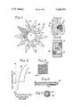
- FIG. 1is a plan view, partly in section, of one embodiment of the heat-absorbing heat sink
- FIG. 2is a plan view of one of the many heat-absorbing portions of the heat sink of FIG. 1;
- FIG. 3is an elevation section view of the heat-absorbing portion of FIG. 2, taken approximately on the line 3--3 of FIG. 2;
- FIG. 4is a graph of temperature versus time for the heat-absorbing heat sink of FIG. 1;
- FIG. 5is a plan view of a mesh or fabric of a multiplicity of fibers containing an embedded heat-absorbing compound
- FIG. 6is a longitudinal view, partly in section, of a metallic yarn made up of a central filament of a heat-absorbing compound twisted and wrapped with many smaller diameter metallic wires;
- FIG. 7is a transverse section view of the yarn of FIG. 6.
- FIG. 1a plan view of a heat sink of one embodiment of this invention is shown.
- a metallic, star-shaped heat sink 10surrounds a heat-generating power transistor to be inserted at 12.
- the star shapeis conventional, aiding in heat transfer by convection and radiation.
- the star-shaped metal piece 14has many cylindrical openings 16 to surround heat-absorbing compound embedded in cylindrical rolls of wire mesh 18.
- FIG. 2shows a plan view of one of the cylindrical rolls of wire mesh 18 with embedded heat absorbing compound.
- the meshis rolled to a diameter approximately equal to the diameter of the opening 16 in the star-shaped metal piece 14 and press fit into the metal. All openings 16 are similarly filled.
- FIG. 3shows a section view of one of the cylindrical rolls of wire mesh 18 in place in an opening 16 in the star-shaped piece 14.
- This embodiment of the inventionuses thick sections of mesh and heat-absorbing compound. It is clear that the mesh fibers must have high heat conductivity to avoid appreciable temperature differentials within the heat sink. Metal fiber is a clear choice. Copper has very high conductivity and also absorbs and retains a wide variety of heat-absorbing materials. A heat-absorbing compound well suited for this application is a tertiary eutectic alloy of Bismuth, Lead and Tin. The melting point can be adjusted, by adjusting the proportions of the elements in the compound, over the appropriate temperature range of 70° C. to 85° C. Copper mesh can absorb and retain these alloys to the extent that the mass of the contained alloy is as great as the mass of the mesh. For Application requiring a higher melting temperature, Cadmium, Silver, Gold, Antimony and Mercury are effective constituents of the heat-absorbing compound.
- FIG. 4Ashows case temperature versus time-after-start for a transistor installed in a heat sink of the type just described.
- the temperature of the surroundingsis 40° C. and the melting temperature of the Bismuth, Lead, Tin alloy is approximately 72° C.
- FIG. 4Bshows case temperature versus time-after-start for the same conditions except that there are no cylindrical openings 16 in the star shaped metal piece 14 and thus no heat-absorbing compound in the heat sink. This curve shows the performance of an equivalent conventional heat sink.
- the transistoris required to operate for 4.5 minutes.
- the transistor case temperaturewould not go above 72° C., FIG. 4A.
- the transistor case temperaturewould go to a dangerous 88° C., FIG. 4B.
- FIG. 5shows a fiber mesh made with frayed ends 20. These frayed ends when exposed as a surface of the heat sink greatly increase radiation surface area and will create micro turbulence in the stream of convection flow. This increases transfer efficiency of the heat sink in the conventional sense.
- the meshmay be woven of multifilament yarn.
- the meshmay be a common cloth made of cotton, nylon, or linen fibers. In these cases waxes, either animal or mineral, have great utility as the heat-absorbing compound. A wide variety of melting points is available. Waxes are retained very well by non-metallic cloth, and have a high latent heat of fusion.
- FIG. 6 and FIG. 7show a preferred metallic yarn for weaving into a mesh for use in the heat sinks of this invention.
- a central filament 30 of heat-absorbing compoundis wrapped with many smaller diameter metallic filaments 32.
- the cross sectional area of the central filamentis essentially equal to the total cross sectional area of the metallic filaments wrapped around it. This method of construction allows a maximum amount of heat-absorbing compound to be effectively absorbed and retained by the metallic filaments.
Landscapes
- Chemical & Material Sciences (AREA)
- Engineering & Computer Science (AREA)
- Mechanical Engineering (AREA)
- Organic Chemistry (AREA)
- Physics & Mathematics (AREA)
- Metallurgy (AREA)
- Materials Engineering (AREA)
- General Physics & Mathematics (AREA)
- Condensed Matter Physics & Semiconductors (AREA)
- Computer Hardware Design (AREA)
- Microelectronics & Electronic Packaging (AREA)
- Power Engineering (AREA)
- Crystallography & Structural Chemistry (AREA)
- General Engineering & Computer Science (AREA)
- Thermal Sciences (AREA)
- Dispersion Chemistry (AREA)
- Woven Fabrics (AREA)
Abstract
Description
Heat sink has been the traditional name for devices that transfer heat from a heat generator to lower-temperature surroundings with a design objective of minimizing the temperature rise between the heat generator and the surroundings. The purpose is to keep the temperature of the heat generator low to prevent performance degradation or destruction of the generator. Electronic equipment and components wherein a temperature of 50° C. represents a benign environment, but 120° C. represents complete destruction, use heat sinks in great abundance and variety.
The heat sinks of this invention not only transfer heat, they absorb heat. Obviously heat absorption can only exist in a transient situation and a major purpose of such heat sinks is to delay temperature rise until the equipment is no longer required to operate or until the temperature of the surroundings goes down.
Delay in temperature rise can be vitally important. Missiles and space vehicles are only subjected to intense heat for periods of several minutes and often their equipment is only required to operate for several minutes. There are a multitude of other examples wherein heat removal for a short time is a key design requirement.
Two heat-absorbing phenomina are used here. One occurs when using a melting compound in the heat sink. Any solid when melting absorbs heat without temperature rise. The quantity of heat absorbed to convert a unit solid mass to liquid mass at the same temperature is called the latent heat of fusion. The other phenomina occurs when using a compound in the heat sink that undergoes a chemical change at a specific temperature, absorbing heat. Such a reaction is called an endothermic reaction.
It is clear that a change of a solid to a liquid creates the problem of containing the liquid that was once a solid. Similar changes occur in endothermic reactions. Melting compounds have been sealed inside cavities in heat sinks so as not to escape in liquid form. This involves sealing problems including allowance for expansion with temperature, and does not improve heat transfer by covection and radiation as is accomplished by the invention here. The use of heat-absorbing compounds in heat sinks does not appear in any known patent.
A major object of this invention is to provide improved heat sinks that absorb heat, delaying temperature rise, at the melting temperature of a compound embedded within a mesh or fabric of fibers that retains the compound when liquid by capillary action and chemical adhesion. These phenomina are most frequently observed in the way multi-strand wires absorb and retain melted solder. The mesh or fabric, with melting compound embedded, can be used in a variety of ways. It can be wrapped in one or more layers around cylindrical heat generators such as transistors or pipes carrying hot fluids. It can be rolled into cylindrical shapes and installed into round holes in a solid heat sink.
Another object of this invention is to provide improved heat sinks that absorb heat, delaying temperature rise, at the temperature of endothermic chemical change or reaction of a compound embedded within a mesh or fabric or fibers that retains the compound both above and below the temperature of change. While this reaction in some applications may be non-reversible (absorbing heat on first temperature rise only), it is an object of this invention to also provide a reversible reaction when heat generation will occur more than once in the application.
Another object of the invention is to provide a heat-absorbing mesh of high heat conductivity when the mesh is used in thick sections. Otherwise temperature differentials could exist within the heat sink and temperature rises above the critical temperature could occur without some of the heat-absorbing compound being exposed to the critical temperature. When the heat-absorbing mesh is used in thin sections, high heat conductivity of the mesh is not a major concern and the normal criteria of time delay in temperature rise, weight, volume, radiation and convection transfer efficiency, and cost are the predominent criteria.
Another object of this invention is to provide heat sinks with improved convection and radiation heat-transfer characteristics. The mesh employed can greatly increase the surface area of the heat sink as compared to the mass or volume of the heat sink. The mesh may have frayed fiber ends increasing the radiation surface area and creating micro turbulence in the stream of convection flow. Fibers perpendicular to the mesh surface may be embedded into the mesh further increasing the micro turbulence and the effective surface area.
The invention will be better understood by reference to the following figures in which:
FIG. 1 is a plan view, partly in section, of one embodiment of the heat-absorbing heat sink;
FIG. 2 is a plan view of one of the many heat-absorbing portions of the heat sink of FIG. 1;
FIG. 3 is an elevation section view of the heat-absorbing portion of FIG. 2, taken approximately on theline 3--3 of FIG. 2;
FIG. 4 is a graph of temperature versus time for the heat-absorbing heat sink of FIG. 1;
FIG. 5 is a plan view of a mesh or fabric of a multiplicity of fibers containing an embedded heat-absorbing compound;
FIG. 6 is a longitudinal view, partly in section, of a metallic yarn made up of a central filament of a heat-absorbing compound twisted and wrapped with many smaller diameter metallic wires; and
FIG. 7 is a transverse section view of the yarn of FIG. 6.
Referring now to FIG. 1, a plan view of a heat sink of one embodiment of this invention is shown. A metallic, star-shaped heat sink 10 surrounds a heat-generating power transistor to be inserted at 12. The star shape is conventional, aiding in heat transfer by convection and radiation. The star-shaped metal piece 14 has manycylindrical openings 16 to surround heat-absorbing compound embedded in cylindrical rolls ofwire mesh 18.
FIG. 2 shows a plan view of one of the cylindrical rolls ofwire mesh 18 with embedded heat absorbing compound. The mesh is rolled to a diameter approximately equal to the diameter of the opening 16 in the star-shaped metal piece 14 and press fit into the metal. Allopenings 16 are similarly filled.
FIG. 3 shows a section view of one of the cylindrical rolls ofwire mesh 18 in place in an opening 16 in the star-shaped piece 14.
This embodiment of the invention uses thick sections of mesh and heat-absorbing compound. It is clear that the mesh fibers must have high heat conductivity to avoid appreciable temperature differentials within the heat sink. Metal fiber is a clear choice. Copper has very high conductivity and also absorbs and retains a wide variety of heat-absorbing materials. A heat-absorbing compound well suited for this application is a tertiary eutectic alloy of Bismuth, Lead and Tin. The melting point can be adjusted, by adjusting the proportions of the elements in the compound, over the appropriate temperature range of 70° C. to 85° C. Copper mesh can absorb and retain these alloys to the extent that the mass of the contained alloy is as great as the mass of the mesh. For Application requiring a higher melting temperature, Cadmium, Silver, Gold, Antimony and Mercury are effective constituents of the heat-absorbing compound.
FIG. 4A shows case temperature versus time-after-start for a transistor installed in a heat sink of the type just described. The temperature of the surroundings is 40° C. and the melting temperature of the Bismuth, Lead, Tin alloy is approximately 72° C.
FIG. 4B shows case temperature versus time-after-start for the same conditions except that there are nocylindrical openings 16 in the star shapedmetal piece 14 and thus no heat-absorbing compound in the heat sink. This curve shows the performance of an equivalent conventional heat sink.
Suppose that in a missile application, the transistor is required to operate for 4.5 minutes. With the heat sink of this invention the transistor case temperature would not go above 72° C., FIG. 4A. With a conventional heat sink of the same size and weight, the transistor case temperature would go to a dangerous 88° C., FIG. 4B.
FIG. 5 shows a fiber mesh made with frayed ends 20. These frayed ends when exposed as a surface of the heat sink greatly increase radiation surface area and will create micro turbulence in the stream of convection flow. This increases transfer efficiency of the heat sink in the conventional sense. The mesh may be woven of multifilament yarn. When the heat-absorbing compound is used in thin sections, and high heat conductivity is not required, the mesh may be a common cloth made of cotton, nylon, or linen fibers. In these cases waxes, either animal or mineral, have great utility as the heat-absorbing compound. A wide variety of melting points is available. Waxes are retained very well by non-metallic cloth, and have a high latent heat of fusion.
FIG. 6 and FIG. 7 show a preferred metallic yarn for weaving into a mesh for use in the heat sinks of this invention. Acentral filament 30 of heat-absorbing compound is wrapped with many smaller diametermetallic filaments 32. The cross sectional area of the central filament is essentially equal to the total cross sectional area of the metallic filaments wrapped around it. This method of construction allows a maximum amount of heat-absorbing compound to be effectively absorbed and retained by the metallic filaments.
Claims (12)
1. An improved heat sink device for transferring heat from a heat generator to lower-temperature surroundings by radiation, covection, and conduction, wherein the improvement comprises: a device-embedded compound that absorbs heat at a specific temperature, delaying temperature rise in the heat generator; and a multiplicity of fibers to absorb and retain said compound within the device, both below and above said specific temperature, said fibers being partially exposed as an outer surface of the device providing heat transfer by radiation and convection.
2. A heat sink as in claim 1 wherein said compound melts at said specific temperature absorbing without temperature rise a quantity of heat proportional to the latent heat of fusion of the compound, and said multiplicity of fibers comprises metallic wire structured as a mesh of one or more layers.
3. A heat sink as in claim 2 wherein the constituents of said compound are selected from the group consisting of lead, tin, bismuth, gold, silver, cadmium, antimony, and mercury.
4. A heat sink as in claim 3 wherein said compound is a tertiary eutectic alloy comprising bismuth, lead, and tin.
5. A heat sink as in claim 1 wherein said compound is a wax that melts at said specific temperature absorbing without temperature rise a quantity of heat proportional to the latent heat of fusion of the wax and said multiplicity of fibers are structured as a cloth of one or more layers.
6. A heat sink as in claim 5 wherein said cloth is selected from the group consisting of cotton, nylon, and linen.
7. A heat sink as in claim 1 wherein said compound undergoes an endothermic chemical change at the said specific temperature absorbing heat without appreciable temperature rise.
8. A heat sink as in claim 7 wherein said compound can undergo repeated endothermic chemical change when temperature-cycled above and below said specific temperature.
9. An improved heat sink device for transferring heat from a heat generator to lower-temperature surroundings, wherein the improvement comprises: a device-embedded compound formed in filaments that melt at a specific temperature absorbing without temperature rise a quantity of heat proportional to the latent heat of fusion of said compound delaying temperature rise in the heat generator, said filaments first being wrapped and twisted with many smaller diameter metallic wires to form yarn which is then woven into a mesh used in at least one layer, said metallic wires absorbing and retaining said compound within the device, both below and above said specific temperature.
10. An improved heat sink device for transferring heat from a heat generator to lower-temperature surroundings, wherein the improvement comprises: a device-embedded metallic compound formed in filaments that melt at a specific temperature absorbing without temperature rise a quantity of heat proportional to the latent heat of fusion of said compound delaying temperature rise in the heat generator, said filaments first being wrapped and twisted with many smaller diameter metallic wires to form yarn which is then woven into a mesh used in at least one layer, said metallic wires absorbing and retaining said compound within the device, both below and above said specific temperature.
11. A heat sink as in claim 10 wherein the constituents of said compound are selected from the group consisting of lead, tin, bismuth, gold, silver, cadmium, antimony, and mercury.
12. A heat sink as in claim 11 wherein said compound is a tertiary eutectic alloy comprising bismuth, lead, and tin.
Priority Applications (1)
| Application Number | Priority Date | Filing Date | Title |
|---|---|---|---|
| US06/292,639US4446916A (en) | 1981-08-13 | 1981-08-13 | Heat-absorbing heat sink |
Applications Claiming Priority (1)
| Application Number | Priority Date | Filing Date | Title |
|---|---|---|---|
| US06/292,639US4446916A (en) | 1981-08-13 | 1981-08-13 | Heat-absorbing heat sink |
Publications (1)
| Publication Number | Publication Date |
|---|---|
| US4446916Atrue US4446916A (en) | 1984-05-08 |
Family
ID=23125529
Family Applications (1)
| Application Number | Title | Priority Date | Filing Date |
|---|---|---|---|
| US06/292,639Expired - LifetimeUS4446916A (en) | 1981-08-13 | 1981-08-13 | Heat-absorbing heat sink |
Country Status (1)
| Country | Link |
|---|---|
| US (1) | US4446916A (en) |
Cited By (50)
| Publication number | Priority date | Publication date | Assignee | Title |
|---|---|---|---|---|
| FR2551619A1 (en)* | 1983-09-07 | 1985-03-08 | Sundstrand Data Control | HEAT PROTECTED MEMORY UNIT FOR AN AIRCRAFT FLIGHT DATA RECORDER |
| US4694119A (en)* | 1983-09-07 | 1987-09-15 | Sundstrand Data Control, Inc. | Heat shielded memory unit for an aircraft flight data recorder |
| EP0264892A3 (en)* | 1986-10-20 | 1988-07-27 | Fujitsu Limited | Cooling objects, for example semiconductor devices |
| US4940480A (en)* | 1987-10-19 | 1990-07-10 | Vitro Tec Fideicomiso | Molding cooling system for the manufacture of glass articles or similar materials |
| US5225630A (en)* | 1991-06-18 | 1993-07-06 | Cooper Power Systems, Inc. | Transformer assembly having cooling fins and method of providing same |
| US5268815A (en)* | 1992-02-14 | 1993-12-07 | International Business Machines Corporation | High density, high performance memory circuit package |
| US5486937A (en)* | 1991-10-18 | 1996-01-23 | Nippon Sheet Glass Co., Ltd. | Latex containment means for a liquid crystal window |
| US5505121A (en)* | 1994-12-09 | 1996-04-09 | Spector; Donald | Composite cup stand and oven unit |
| US5516345A (en)* | 1994-06-30 | 1996-05-14 | Iowa State University Research Foundation, Inc. | Latent heat-ballasted gasifier method |
| US5528463A (en)* | 1993-07-16 | 1996-06-18 | Dallas Semiconductor Corp. | Low profile sockets and modules for surface mountable applications |
| FR2732361A1 (en)* | 1995-03-29 | 1996-10-04 | Serole Bernard | Retarding flow of metal body, e.g. sputtering target |
| US5579206A (en)* | 1993-07-16 | 1996-11-26 | Dallas Semiconductor Corporation | Enhanced low profile sockets and module systems |
| US5709914A (en)* | 1994-01-18 | 1998-01-20 | Hayes; Claude Q. C. | Thermal storage and transfer device |
| US5783862A (en)* | 1992-03-20 | 1998-07-21 | Hewlett-Packard Co. | Electrically conductive thermal interface |
| US5853045A (en)* | 1995-03-31 | 1998-12-29 | Patry; Jean | Accumulator-exchanger device |
| WO1999011455A1 (en)* | 1997-09-04 | 1999-03-11 | Hayes, Claude, Q., C. | A thermal storage and transfer device |
| US5913552A (en)* | 1993-06-09 | 1999-06-22 | Dallas Semiconductor Corporation | Method of providing thermal protection of electrical elements |
| US5932839A (en)* | 1997-11-04 | 1999-08-03 | Ren; Jane | Method for dissipating heat away from a heat sensitive device using bicarbonate compositions |
| WO2000033628A1 (en)* | 1998-12-02 | 2000-06-08 | Intel Corporation | A fibrous thermal interface adaptor |
| US6077597A (en)* | 1997-11-14 | 2000-06-20 | Outlast Technologies, Inc. | Interactive thermal insulating system having a layer treated with a coating of energy absorbing phase change material adjacent a layer of fibers containing energy absorbing phase change material |
| US6121680A (en)* | 1999-02-16 | 2000-09-19 | Intel Corporation | Mesh structure to avoid thermal grease pump-out in integrated circuit heat sink attachments |
| US6153720A (en)* | 1998-04-02 | 2000-11-28 | Alliedsignal Inc. | Data and cockpit voice recorder enclosure |
| US6365244B1 (en)* | 1997-11-04 | 2002-04-02 | Honeywell International, Inc. | Method for heat absorption using polyoxymethylene polymer compositions |
| WO2002011504A3 (en)* | 2000-07-31 | 2002-07-18 | Intel Corp | Thermal interface material on a mesh carrier |
| US6733697B2 (en) | 2002-07-22 | 2004-05-11 | Michael S. Rhodes | Activated flame retardants and their applications |
| US20040253397A1 (en)* | 1995-09-07 | 2004-12-16 | Hayes Claude Q.C. | Heat absorbing temperature control devices that include hydroxide |
| US20050141194A1 (en)* | 2003-12-29 | 2005-06-30 | International Business Machines Corporation | Acoustic and thermal energy management system |
| US6959753B1 (en)* | 1995-03-17 | 2005-11-01 | Raytheon Company | Construction of phase change material embedded electronic circuit boards and electronic circuit board assemblies using porous and fibrous media |
| US7069975B1 (en) | 1999-09-16 | 2006-07-04 | Raytheon Company | Method and apparatus for cooling with a phase change material and heat pipes |
| US7135424B2 (en) | 2001-01-25 | 2006-11-14 | Outlast Technologies, Inc. | Coated articles having enhanced reversible thermal properties and exhibiting improved flexibility, softness, air permeability, or water vapor transport properties |
| US20090059531A1 (en)* | 2007-08-31 | 2009-03-05 | Hayes & Associates | Endotherm Systems and Methods Utilizing Carbohydrate In Non-Oxidizing Environment |
| US20090301562A1 (en)* | 2008-06-05 | 2009-12-10 | Stion Corporation | High efficiency photovoltaic cell and manufacturing method |
| US20100032221A1 (en)* | 2008-08-07 | 2010-02-11 | Charles Robert Storey | Electrolysis system for hydrogen and oxygen production |
| EP2154462A1 (en)* | 2008-08-13 | 2010-02-17 | BAE Systems PLC | Latent heat storage body |
| US20100038053A1 (en)* | 2008-08-15 | 2010-02-18 | Maxik Fredric S | Sustainable endothermic heat stripping method and apparatus |
| US20100059205A1 (en)* | 2002-04-29 | 2010-03-11 | Kauppila Richard W | Cooling arrangement for conveyors and other applications |
| US20100229921A1 (en)* | 2009-03-16 | 2010-09-16 | Stion Corporation | Tandem photovoltaic cell and method using three glass substrate configuration |
| US20110011622A1 (en)* | 2009-07-17 | 2011-01-20 | Searete Llc, A Limited Liability Corporation | Maintaining insulators in power transmission systems |
| US20110013327A1 (en)* | 2009-07-17 | 2011-01-20 | Searete Llc | Smart link coupled to power line |
| US20110012615A1 (en)* | 2009-07-17 | 2011-01-20 | Searete Llc, A Limited Liability Corporation | Systems and methods for assessing standoff capabilities of in-sevice power line insulators |
| US20110012583A1 (en)* | 2009-07-17 | 2011-01-20 | Searete Llc, A Limited Liability Corporation Of The State Of Delaware | Use pairs of transformers to increase transmission line voltage |
| US20110017257A1 (en)* | 2008-08-27 | 2011-01-27 | Stion Corporation | Multi-junction solar module and method for current matching between a plurality of first photovoltaic devices and second photovoltaic devices |
| US20110101989A1 (en)* | 2009-07-17 | 2011-05-05 | Searete Llc, A Limited Liability Corporation Of The State Of Delaware | Systems and methods for testing the standoff capability of an overhead power transmission line |
| US20110168245A1 (en)* | 2008-08-28 | 2011-07-14 | Stion Corporation | Four Terminal Multi-Junction Thin Film Photovoltaic Device and Method |
| US8569613B1 (en) | 2008-09-29 | 2013-10-29 | Stion Corporation | Multi-terminal photovoltaic module including independent cells and related system |
| US20140352932A1 (en)* | 2012-07-18 | 2014-12-04 | Honeywell International Inc. | Systems and methods for a protective casing |
| US8907206B2 (en) | 2007-11-14 | 2014-12-09 | Stion Corporation | Multi-junction solar cell devices |
| US9041195B2 (en) | 2012-12-31 | 2015-05-26 | International Business Machines Corporation | Phase changing on-chip thermal heat sink |
| US9449440B2 (en) | 2014-09-17 | 2016-09-20 | Honeywell International Inc. | Wireless crash survivable memory unit |
| US20180149437A1 (en)* | 2016-11-30 | 2018-05-31 | The Boeing Company | Thermal Management Device and Method Using Phase Change Material |
Citations (13)
| Publication number | Priority date | Publication date | Assignee | Title |
|---|---|---|---|---|
| US2677367A (en)* | 1951-04-25 | 1954-05-04 | Telkes Maria | Heat storage unit |
| FR1153115A (en)* | 1955-04-07 | 1958-03-03 | Bendix Aviat Corp | Heat-insulating material, its manufacturing processes and its applications, in particular in aeronautics |
| CA600823A (en)* | 1960-06-28 | Canadian General Electric Company | Mounting device for semiconductor devices and the like | |
| US2964688A (en)* | 1959-08-03 | 1960-12-13 | Int Electronic Res Corp | Heat dissipators for transistors |
| US3780356A (en)* | 1969-02-27 | 1973-12-18 | Laing Nikolaus | Cooling device for semiconductor components |
| US3972821A (en)* | 1973-04-30 | 1976-08-03 | Amchem Products, Inc. | Heat transfer composition and method of making |
| US4003426A (en)* | 1975-05-08 | 1977-01-18 | The Dow Chemical Company | Heat or thermal energy storage structure |
| US4057101A (en)* | 1976-03-10 | 1977-11-08 | Westinghouse Electric Corporation | Heat sink |
| US4135371A (en)* | 1976-05-18 | 1979-01-23 | Fritz Kesselring | Storage element for a sorption heat storage system |
| US4187189A (en)* | 1978-05-02 | 1980-02-05 | American Technological University | Phase change thermal storage materials with crust forming stabilizers |
| US4233645A (en)* | 1978-10-02 | 1980-11-11 | International Business Machines Corporation | Semiconductor package with improved conduction cooling structure |
| US4299715A (en)* | 1978-04-14 | 1981-11-10 | Whitfield Fred J | Methods and materials for conducting heat from electronic components and the like |
| US4341262A (en)* | 1980-05-05 | 1982-07-27 | Alspaugh Thomas R | Energy storage system and method |
- 1981
- 1981-08-13USUS06/292,639patent/US4446916A/ennot_activeExpired - Lifetime
Patent Citations (13)
| Publication number | Priority date | Publication date | Assignee | Title |
|---|---|---|---|---|
| CA600823A (en)* | 1960-06-28 | Canadian General Electric Company | Mounting device for semiconductor devices and the like | |
| US2677367A (en)* | 1951-04-25 | 1954-05-04 | Telkes Maria | Heat storage unit |
| FR1153115A (en)* | 1955-04-07 | 1958-03-03 | Bendix Aviat Corp | Heat-insulating material, its manufacturing processes and its applications, in particular in aeronautics |
| US2964688A (en)* | 1959-08-03 | 1960-12-13 | Int Electronic Res Corp | Heat dissipators for transistors |
| US3780356A (en)* | 1969-02-27 | 1973-12-18 | Laing Nikolaus | Cooling device for semiconductor components |
| US3972821A (en)* | 1973-04-30 | 1976-08-03 | Amchem Products, Inc. | Heat transfer composition and method of making |
| US4003426A (en)* | 1975-05-08 | 1977-01-18 | The Dow Chemical Company | Heat or thermal energy storage structure |
| US4057101A (en)* | 1976-03-10 | 1977-11-08 | Westinghouse Electric Corporation | Heat sink |
| US4135371A (en)* | 1976-05-18 | 1979-01-23 | Fritz Kesselring | Storage element for a sorption heat storage system |
| US4299715A (en)* | 1978-04-14 | 1981-11-10 | Whitfield Fred J | Methods and materials for conducting heat from electronic components and the like |
| US4187189A (en)* | 1978-05-02 | 1980-02-05 | American Technological University | Phase change thermal storage materials with crust forming stabilizers |
| US4233645A (en)* | 1978-10-02 | 1980-11-11 | International Business Machines Corporation | Semiconductor package with improved conduction cooling structure |
| US4341262A (en)* | 1980-05-05 | 1982-07-27 | Alspaugh Thomas R | Energy storage system and method |
Non-Patent Citations (2)
| Title |
|---|
| Chip Cooling Employing a Conformable Alloy, Hassan et al., I.B.M. Technical Disclosure Bulletin, vol. 24, No. 11A, pp. 5595 5597.* |
| Chip Cooling Employing a Conformable Alloy, Hassan et al., I.B.M. Technical Disclosure Bulletin, vol. 24, No. 11A, pp. 5595-5597. |
Cited By (93)
| Publication number | Priority date | Publication date | Assignee | Title |
|---|---|---|---|---|
| US4694119A (en)* | 1983-09-07 | 1987-09-15 | Sundstrand Data Control, Inc. | Heat shielded memory unit for an aircraft flight data recorder |
| FR2551619A1 (en)* | 1983-09-07 | 1985-03-08 | Sundstrand Data Control | HEAT PROTECTED MEMORY UNIT FOR AN AIRCRAFT FLIGHT DATA RECORDER |
| EP0264892A3 (en)* | 1986-10-20 | 1988-07-27 | Fujitsu Limited | Cooling objects, for example semiconductor devices |
| US5012858A (en)* | 1986-10-20 | 1991-05-07 | Fujitsu Limited | Method of cooling a semiconductor device with a cooling unit, using metal sherbet between the device and the cooling unit |
| US4940480A (en)* | 1987-10-19 | 1990-07-10 | Vitro Tec Fideicomiso | Molding cooling system for the manufacture of glass articles or similar materials |
| US5225630A (en)* | 1991-06-18 | 1993-07-06 | Cooper Power Systems, Inc. | Transformer assembly having cooling fins and method of providing same |
| US5486937A (en)* | 1991-10-18 | 1996-01-23 | Nippon Sheet Glass Co., Ltd. | Latex containment means for a liquid crystal window |
| US5268815A (en)* | 1992-02-14 | 1993-12-07 | International Business Machines Corporation | High density, high performance memory circuit package |
| US5783862A (en)* | 1992-03-20 | 1998-07-21 | Hewlett-Packard Co. | Electrically conductive thermal interface |
| US6021046A (en)* | 1993-06-09 | 2000-02-01 | Dallas Semiconductor Corporation | Thermal protection of electrical elements systems |
| US5913552A (en)* | 1993-06-09 | 1999-06-22 | Dallas Semiconductor Corporation | Method of providing thermal protection of electrical elements |
| US5528463A (en)* | 1993-07-16 | 1996-06-18 | Dallas Semiconductor Corp. | Low profile sockets and modules for surface mountable applications |
| US5579206A (en)* | 1993-07-16 | 1996-11-26 | Dallas Semiconductor Corporation | Enhanced low profile sockets and module systems |
| US5709914A (en)* | 1994-01-18 | 1998-01-20 | Hayes; Claude Q. C. | Thermal storage and transfer device |
| US5711771A (en)* | 1994-06-30 | 1998-01-27 | Iowa State University Research Foundation, Inc. | Latent heat-ballasted gasifier |
| US5516345A (en)* | 1994-06-30 | 1996-05-14 | Iowa State University Research Foundation, Inc. | Latent heat-ballasted gasifier method |
| US5505121A (en)* | 1994-12-09 | 1996-04-09 | Spector; Donald | Composite cup stand and oven unit |
| US6959753B1 (en)* | 1995-03-17 | 2005-11-01 | Raytheon Company | Construction of phase change material embedded electronic circuit boards and electronic circuit board assemblies using porous and fibrous media |
| FR2732361A1 (en)* | 1995-03-29 | 1996-10-04 | Serole Bernard | Retarding flow of metal body, e.g. sputtering target |
| US5853045A (en)* | 1995-03-31 | 1998-12-29 | Patry; Jean | Accumulator-exchanger device |
| US7566484B2 (en) | 1995-09-07 | 2009-07-28 | Hayes And Associates | Heat absorbing temperature control devices that include hydroxide |
| US20040253397A1 (en)* | 1995-09-07 | 2004-12-16 | Hayes Claude Q.C. | Heat absorbing temperature control devices that include hydroxide |
| CZ299714B6 (en)* | 1997-09-04 | 2008-10-29 | Thermal storage and transfer device | |
| WO1999011455A1 (en)* | 1997-09-04 | 1999-03-11 | Hayes, Claude, Q., C. | A thermal storage and transfer device |
| US5932839A (en)* | 1997-11-04 | 1999-08-03 | Ren; Jane | Method for dissipating heat away from a heat sensitive device using bicarbonate compositions |
| US6365244B1 (en)* | 1997-11-04 | 2002-04-02 | Honeywell International, Inc. | Method for heat absorption using polyoxymethylene polymer compositions |
| US6077597A (en)* | 1997-11-14 | 2000-06-20 | Outlast Technologies, Inc. | Interactive thermal insulating system having a layer treated with a coating of energy absorbing phase change material adjacent a layer of fibers containing energy absorbing phase change material |
| US6217993B1 (en) | 1997-11-14 | 2001-04-17 | Outlast Technologies, Inc. | Interactive thermal insulating system having a layer treated with a coating of energy absorbing phase change material adjacent a layer of fibers containing energy absorbing phase change material |
| US6153720A (en)* | 1998-04-02 | 2000-11-28 | Alliedsignal Inc. | Data and cockpit voice recorder enclosure |
| WO2000033628A1 (en)* | 1998-12-02 | 2000-06-08 | Intel Corporation | A fibrous thermal interface adaptor |
| US6150195A (en)* | 1999-02-16 | 2000-11-21 | Intel Corporation | Method for an integrated circuit thermal grease mesh structure |
| US6121680A (en)* | 1999-02-16 | 2000-09-19 | Intel Corporation | Mesh structure to avoid thermal grease pump-out in integrated circuit heat sink attachments |
| US7069975B1 (en) | 1999-09-16 | 2006-07-04 | Raytheon Company | Method and apparatus for cooling with a phase change material and heat pipes |
| US20060293086A1 (en)* | 1999-09-16 | 2006-12-28 | Raytheon Company | Method and apparatus for cooling with a phase change material and heat pipes |
| US7416017B2 (en) | 1999-09-16 | 2008-08-26 | Raytheon Company | Method and apparatus for cooling with a phase change material and heat pipes |
| US6523608B1 (en) | 2000-07-31 | 2003-02-25 | Intel Corporation | Thermal interface material on a mesh carrier |
| WO2002011504A3 (en)* | 2000-07-31 | 2002-07-18 | Intel Corp | Thermal interface material on a mesh carrier |
| US7135424B2 (en) | 2001-01-25 | 2006-11-14 | Outlast Technologies, Inc. | Coated articles having enhanced reversible thermal properties and exhibiting improved flexibility, softness, air permeability, or water vapor transport properties |
| US8579014B2 (en)* | 2002-04-29 | 2013-11-12 | Richard W. Kauppila | Cooling arrangement for conveyors and other applications |
| US20100059205A1 (en)* | 2002-04-29 | 2010-03-11 | Kauppila Richard W | Cooling arrangement for conveyors and other applications |
| US6733697B2 (en) | 2002-07-22 | 2004-05-11 | Michael S. Rhodes | Activated flame retardants and their applications |
| US7116555B2 (en)* | 2003-12-29 | 2006-10-03 | International Business Machines Corporation | Acoustic and thermal energy management system |
| US20050141194A1 (en)* | 2003-12-29 | 2005-06-30 | International Business Machines Corporation | Acoustic and thermal energy management system |
| US20090059531A1 (en)* | 2007-08-31 | 2009-03-05 | Hayes & Associates | Endotherm Systems and Methods Utilizing Carbohydrate In Non-Oxidizing Environment |
| US9546312B2 (en) | 2007-08-31 | 2017-01-17 | Hayes & Associates | Endotherm systems and methods utilizing carbohydrate in non-oxidizing environment |
| US8907206B2 (en) | 2007-11-14 | 2014-12-09 | Stion Corporation | Multi-junction solar cell devices |
| US20090301562A1 (en)* | 2008-06-05 | 2009-12-10 | Stion Corporation | High efficiency photovoltaic cell and manufacturing method |
| US20100032221A1 (en)* | 2008-08-07 | 2010-02-11 | Charles Robert Storey | Electrolysis system for hydrogen and oxygen production |
| EP2154462A1 (en)* | 2008-08-13 | 2010-02-17 | BAE Systems PLC | Latent heat storage body |
| US20100038053A1 (en)* | 2008-08-15 | 2010-02-18 | Maxik Fredric S | Sustainable endothermic heat stripping method and apparatus |
| US8631855B2 (en) | 2008-08-15 | 2014-01-21 | Lighting Science Group Corporation | System for dissipating heat energy |
| US20110017257A1 (en)* | 2008-08-27 | 2011-01-27 | Stion Corporation | Multi-junction solar module and method for current matching between a plurality of first photovoltaic devices and second photovoltaic devices |
| US20110168245A1 (en)* | 2008-08-28 | 2011-07-14 | Stion Corporation | Four Terminal Multi-Junction Thin Film Photovoltaic Device and Method |
| US8569613B1 (en) | 2008-09-29 | 2013-10-29 | Stion Corporation | Multi-terminal photovoltaic module including independent cells and related system |
| US20100229921A1 (en)* | 2009-03-16 | 2010-09-16 | Stion Corporation | Tandem photovoltaic cell and method using three glass substrate configuration |
| US8563850B2 (en) | 2009-03-16 | 2013-10-22 | Stion Corporation | Tandem photovoltaic cell and method using three glass substrate configuration |
| US20110013327A1 (en)* | 2009-07-17 | 2011-01-20 | Searete Llc | Smart link coupled to power line |
| US20110011622A1 (en)* | 2009-07-17 | 2011-01-20 | Searete Llc, A Limited Liability Corporation | Maintaining insulators in power transmission systems |
| US20110101989A1 (en)* | 2009-07-17 | 2011-05-05 | Searete Llc, A Limited Liability Corporation Of The State Of Delaware | Systems and methods for testing the standoff capability of an overhead power transmission line |
| US20110012583A1 (en)* | 2009-07-17 | 2011-01-20 | Searete Llc, A Limited Liability Corporation Of The State Of Delaware | Use pairs of transformers to increase transmission line voltage |
| US20110215790A1 (en)* | 2009-07-17 | 2011-09-08 | Searete Llc | Use pairs of transformers to increase transmission line voltage |
| US8174270B2 (en) | 2009-07-17 | 2012-05-08 | The Invention Science Fund I, Llc | Systems and methods for assessing standoff capabilities of in-service power line insulators |
| US8248080B2 (en) | 2009-07-17 | 2012-08-21 | The Invention Science Fund I, Llc | Systems and methods for assessing standoff capabilities of in-service power line insulators |
| US8253525B2 (en)* | 2009-07-17 | 2012-08-28 | The Invention Science Fund I, Llc | Smart link coupled to power line |
| US8426736B2 (en) | 2009-07-17 | 2013-04-23 | The Invention Science Fund I Llc | Maintaining insulators in power transmission systems |
| US8427800B2 (en) | 2009-07-17 | 2013-04-23 | The Invention Science Fund I Llc | Smart link coupled to power line |
| US8456168B2 (en) | 2009-07-17 | 2013-06-04 | The Invention Science Fund I Llc | Systems and methods for testing the standoff capability of an overhead power transmission line |
| US20110012706A1 (en)* | 2009-07-17 | 2011-01-20 | Searete Llc | Smart link coupled to power line |
| US8563867B2 (en) | 2009-07-17 | 2013-10-22 | The Invention Science Fund I, Llc | Smart link coupled to power line |
| US20110011623A1 (en)* | 2009-07-17 | 2011-01-20 | Searete Llc | Smart link coupled to power line |
| US20110012615A1 (en)* | 2009-07-17 | 2011-01-20 | Searete Llc, A Limited Liability Corporation | Systems and methods for assessing standoff capabilities of in-sevice power line insulators |
| US20110011621A1 (en)* | 2009-07-17 | 2011-01-20 | Searete Llc, A Limited Liability Corporation Of The State Of Delaware | Smart link coupled to power line |
| US8692537B2 (en) | 2009-07-17 | 2014-04-08 | The Invention Science Fund I, Llc | Use pairs of transformers to increase transmission line voltage |
| US20110011624A1 (en)* | 2009-07-17 | 2011-01-20 | Searete Llc | Smart link coupled to power line |
| US8907529B2 (en) | 2009-07-17 | 2014-12-09 | The Invention Science Fund I, Llc | Smart link coupled to power line |
| US20110012437A1 (en)* | 2009-07-17 | 2011-01-20 | Searete Llc | Maintaining insulators in power transmission systems |
| US9225170B2 (en) | 2009-07-17 | 2015-12-29 | The Invention Science Fund I, Llc | Use pairs of transformers to increase transmission line voltage |
| US9505550B2 (en)* | 2012-07-18 | 2016-11-29 | Honeywell International Inc. | Systems and methods for a protective casing |
| US20140352932A1 (en)* | 2012-07-18 | 2014-12-04 | Honeywell International Inc. | Systems and methods for a protective casing |
| US10157816B2 (en) | 2012-12-31 | 2018-12-18 | International Business Machines Corporation | Phase changing on-chip thermal heat sink |
| US9984954B2 (en) | 2012-12-31 | 2018-05-29 | International Business Machines Corporation | Phase changing on-chip thermal heat sink |
| US11004770B2 (en) | 2012-12-31 | 2021-05-11 | International Business Machines Corporation | Phase changing on-chip thermal heat sink |
| US9287141B2 (en) | 2012-12-31 | 2016-03-15 | International Business Machines Corporation | Phase changing on-chip thermal heat sink |
| US9041195B2 (en) | 2012-12-31 | 2015-05-26 | International Business Machines Corporation | Phase changing on-chip thermal heat sink |
| US9704778B2 (en) | 2012-12-31 | 2017-07-11 | International Business Machines Corporation | Phase changing on-chip thermal heat sink |
| US9911682B2 (en) | 2012-12-31 | 2018-03-06 | International Business Machines Corporation | Phase changing on-chip thermal heat sink |
| US9312147B2 (en) | 2012-12-31 | 2016-04-12 | International Business Machines Corporation | Phase changing on-chip thermal heat sink |
| US10177071B2 (en) | 2012-12-31 | 2019-01-08 | International Business Machines Corporation | Phase changing on-chip thermal heat sink |
| US10032691B2 (en) | 2012-12-31 | 2018-07-24 | International Business Machines Corporation | Phase changing on-chip thermal heat sink |
| US9059130B2 (en) | 2012-12-31 | 2015-06-16 | International Business Machines Corporation | Phase changing on-chip thermal heat sink |
| US9449440B2 (en) | 2014-09-17 | 2016-09-20 | Honeywell International Inc. | Wireless crash survivable memory unit |
| US20180149437A1 (en)* | 2016-11-30 | 2018-05-31 | The Boeing Company | Thermal Management Device and Method Using Phase Change Material |
| US10828853B2 (en)* | 2016-11-30 | 2020-11-10 | The Boeing Company | Thermal management device and method using phase change material |
Similar Documents
| Publication | Publication Date | Title |
|---|---|---|
| US4446916A (en) | Heat-absorbing heat sink | |
| US5000252A (en) | Thermal energy storage system | |
| US5224356A (en) | Method of using thermal energy absorbing and conducting potting materials | |
| US5315154A (en) | Electronic assembly including heat absorbing material for limiting temperature through isothermal solid-solid phase transition | |
| US5290904A (en) | Heat shield | |
| US7213637B2 (en) | Heat pipe operating fluid, heat pipe, and method for manufacturing the heat pipe | |
| US4116266A (en) | Apparatus for heat transfer | |
| US20030141045A1 (en) | Heat pipe and method of manufacturing the same | |
| US3780356A (en) | Cooling device for semiconductor components | |
| US4901790A (en) | Self-heated diffuser assembly for a heat pipe | |
| US5325913A (en) | Module cooling system | |
| WO2005114084A1 (en) | Integrated circuit heat pipe heat spreader with through mounting holes | |
| US5831831A (en) | Bonding material and phase change material system for heat burst dissipation | |
| US4313492A (en) | Micro helix thermo capsule | |
| US4683940A (en) | Unidirectional heat pipe | |
| KR900017721A (en) | Low melting temperature solder composition | |
| Colvin et al. | Enhanced heat transport in environmental systems using microencapsulated phase change materials | |
| DE202007014238U1 (en) | Device for heat transfer of a heatpipe condenser | |
| DE1601226A1 (en) | Heating pipes | |
| DE3027711A1 (en) | DEVICE FOR USING SOLAR ENERGY | |
| Gupta et al. | A review on augmentation in thermal performance of solar water heater using phase change material | |
| JP4069301B2 (en) | Composite plate heat pipe | |
| DE2015518A1 (en) | Cooling device for heat generating equipment | |
| JPS5938513B2 (en) | Heat pipe with fins for waste heat recovery | |
| DE10334433B4 (en) | Device for interrupting the flow of current to or from a semiconductor body of a semiconductor device |
Legal Events
| Date | Code | Title | Description |
|---|---|---|---|
| STCF | Information on status: patent grant | Free format text:PATENTED CASE | |
| FEPP | Fee payment procedure | Free format text:PAYOR NUMBER ASSIGNED (ORIGINAL EVENT CODE: ASPN); ENTITY STATUS OF PATENT OWNER: SMALL ENTITY | |
| FPAY | Fee payment | Year of fee payment:4 | |
| FPAY | Fee payment | Year of fee payment:8 | |
| FPAY | Fee payment | Year of fee payment:12 |