US4445741A - Double-plug seismic connector - Google Patents
Double-plug seismic connectorDownload PDFInfo
- Publication number
- US4445741A US4445741AUS06/310,387US31038781AUS4445741AUS 4445741 AUS4445741 AUS 4445741AUS 31038781 AUS31038781 AUS 31038781AUS 4445741 AUS4445741 AUS 4445741A
- Authority
- US
- United States
- Prior art keywords
- plug
- pair
- male
- female
- electric
- Prior art date
- Legal status (The legal status is an assumption and is not a legal conclusion. Google has not performed a legal analysis and makes no representation as to the accuracy of the status listed.)
- Expired - Lifetime
Links
Images


Classifications
- H—ELECTRICITY
- H01—ELECTRIC ELEMENTS
- H01R—ELECTRICALLY-CONDUCTIVE CONNECTIONS; STRUCTURAL ASSOCIATIONS OF A PLURALITY OF MUTUALLY-INSULATED ELECTRICAL CONNECTING ELEMENTS; COUPLING DEVICES; CURRENT COLLECTORS
- H01R25/00—Coupling parts adapted for simultaneous co-operation with two or more identical counterparts, e.g. for distributing energy to two or more circuits
- H01R25/003—Coupling parts adapted for simultaneous co-operation with two or more identical counterparts, e.g. for distributing energy to two or more circuits the coupling part being secured only to wires or cables
Definitions
- This inventionrelates to the art of geophone stringing and more particularly to a double-plug seismic connector or takeout clip having a cable adapted to connect a geophone across the male and female contacts in each plug of the connector.
- "spread” cablesare used to interconnect "strings" of geophones to seismic recording instruments.
- Each stringhas one or more single-plug connectors with “leader” cables that connect two or more geophones.
- the leader cableshave T-couplers for making electric junctions therealong.
- the geophone stringsare connected to a connector coupled to a pair of conductor wires in the multi-wire spread cable.
- the geophonesare electrically interconnected with leader cables at spaced intervals in various networks consisting of series and parallel combinations.
- the process of interconnecting geophonesis commonly referred to as "stringing".
- the art of geophone stringinghas been plagued with numerous problems which are described, for example, in U.S. Pat. No. 3,956,575. This patent relates to a hybrid seismic takeout clip which has exposed takeout contacts.
- single-plug connectors and T-type couplersare used for interconnecting geophones and leader cables.
- One type of commercially known T-coupleris a completely molded T around the leader cables' junction; another type is a fastened T formed from two members which are clamped together around the junction, and then the inside of the T is filled with a suitable potting compound.
- Both known T-couplersprovide a waterproof junction, but the molded T is impossible to repair in the field because the seismic crew has no injection molding equipment, while the fastened T requires considerable skill and time to first dismantle and remove the potting compound and then to reassemble and to reshoot the compound into the T.
- T-couplersbecome frequently damaged by physical objects and their outer jackets and housings may be eaten up by rodents, or they become damaged by rough handling. If trouble shooting is very time-consuming or costly, sometimes a very expensive entire geophone string may have to be discarded because the fault cannot be easily located and may lie in a T-coupler.
- the inventionreduces considerably the amount of labor required and hence the cost of stringing geophones.
- the double-plug seismic electric connector or clipcomprises an elongated insulating body.
- a male connector plugis at one end of the body and a female connector plug is at the opposite end of the body.
- the female plughas a sleeve for captivating a cooperable male plug of another double-plug connector.
- Each plughas a pair of male and female contacts.
- a pair of spaced axial conductorsis embedded within the insulating body. Each conductor establishes a conductive path between the male contact in each one of the plugs and the female contact in the opposite plug.
- a cablehaving a pair of conductor wires.
- the inner end of the cableis embedded within the insulating body and each wire inner end is connected to one of the conductors.
- the outer end of the cableextends outwardly of the body of the connector.
- each conductoris a tubular member having at one end an axial bore forming the female contact and at its opposite end having a threaded axial bore for threadedly accepting the male contact.
- An insulating supportis embedded in the body. The support has a pair of axial bores, and each bore accepts a conductor therethrough. The support has another two pairs of auxiliary axial bores. Each pair of auxiliary bores accepts therethrough for anchoring the inner end of one of the wires in the cable.
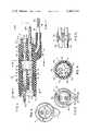
- FIG. 1is a longitudinal sectional view of the double-plug seismic clip of this invention
- FIGS. 2, 3 and 4are views taken on lines 2--2, 3--3 and 4--4, respectively, of FIG. 1;
- FIG. 5is a side view of the pair of embedded conductors showing the knurls thereon;
- FIGS. 6 and 6Aare perspective views of two fully assembled double-plug seismic connectors: in FIG. 6 the leader cable exits near the male plug, and in FIG. 6A it exits near the female plug, otherwise the electric connections in both connectors shown in FIGS. 6, 6A are the same;
- FIG. 7illustrates a prior art method of connecting a geophone or other such device to the connector of a multiwire spread cable with the use of a T-coupler and a pair of conventional male and female single-plug seismic connectors;
- FIG. 8illustrates for comparison with FIG. 7 the use of a double-plug seismic connector of this invention for connecting the geophone of FIG. 7 with the connector of the spread cable without the use of a T-coupler;
- FIG. 9shows a plurality of double-plug seismic connectors interconnected with a pair of prior art single-plug connectors for stringing geophones to the cables protruding outwardly of the double-plug connectors.
- FIGS. 1-6there is shown a double-plug seismic electric takeout connector or clip, generally designated as 10, which comprises an elongated body 11 of generally cylindrical configuration.
- Body 11is made of an insulating elastic material such as a neoprene compound 60 Dur.
- Body 11carries a pair of connector plugs at the opposite ends thereof: a male plug 12 and a female plug 13.
- a frusto-conical support 14preferably made of a rigid block of insulating material such as nylon.
- Support 14has a pair of spaced, axial bores 14a, 14b (FIG. 4), an auxiliary pair of axial bores of smaller diameter 14c, 14'c, and another auxiliary pair of axial bores of smaller diameter 14d, 14'd.
- first electric conductor means 15aSecurely mounted inside bore 14a is a first electric conductor means 15a.
- second electric conductor means 15bSecurely mounted inside bore 14b is a second electric conductor means 15b.
- Each conductor meansis preferably made of a solid brass tube 16. Tubes 16 are of equal length but are axially displaced from each other (FIG. 5) by about 0.65 cm. One end of tube 16 (FIGS. 2, 3) is provided with an unthreaded bore 16a, and the opposite end is provided with a threaded bore 16b. Approximately midway between bores 16a, 16b are provided knurls 16c which serve to anchor each tube 16 to the support 14.
- the inner wall of bore 16aforms a female contact 16'a for accepting therein a male connector part, such as a "banana" pin 16'b (FIG. 6), of an adjacent mating cooperable connector plug.
- a male connector partsuch as a "banana" pin 16'b (FIG. 6)
- Bore 16bthreadedly receives the inner portion of pin 16'b.
- the right-ended side (as viewed in FIG. 1) of body 11has a reduced diameter portion 11a defining a shoulder 11b and an O-ring 11c.
- the left-end side of body 11defines a cylindrical sleeve portion 11d having in the center thereof an annular groove 11e for accepting the O-ring 11c of a mating adjacent male plug 12 (FIG. 9).
- Sleeve 11d of an adjacent female plug 13fits over and captures male plug 12.
- leader cable 18having a pair of insulated conductor wires 18a, 18b.
- the inner end of wire 18apasses through auxiliary bores 14c, 14'c in opposite axial directions so as to form a U-bend 19 with support 14.
- the free end of wire 18ais soldered to conductor 15a at point 19a.
- wire 18bpasses through auxiliary bores 14d, 14'd to form a U-bend 19 and to become soldered at a point 19b on conductor 15b.
- wires 18a, 18bare electrically connected to the contacts 16'a, 16'b of the male and female plugs 12, 13, respectively, and are anchored to support 14 by the U-bends 19 and the soldered joints 19a, 19b.
- Body 11makes the soldered joints 19a, 19b waterproof, while the wires 18a, 18b and the conductors 15a, 15b are anchored to the rigid nylon support 14.
- Connector 10is adapted to become coupled to a female plug and to a male plug at its opposite ends. It also serves as a junction between conductor wires 18a, 18b and the contacts 16'a and 16'b in each of plugs 12 and 13.
- FIG. 7shows a typical prior art method of stringing geophones 20 (only one is shown for simplicity) to a conventional male plug 22 which is connected to a pair of wires 21 inside a spread cable 24 carrying a plurality of conductors 25.
- the typical arrangementincludes a female single-plug connector 23 which cooperatively engages with a male single-plug connector 22.
- a T-coupler 26Utilizing a T-coupler 26, the leader cable 18 connected to female plug 23 is coupled to the leader cable 18 of another male plug 22a and to the leader cable 18 connected to geophone 20.
- T-couplers 26are employed as described in said U.S. Pat. No. 3,956,575 for making a geophone string which interconnects a plurality of geophones 20.
- the other connector plug 22aconnects the geophone string to another string or to a recording instrument.
- FIG. 8illustrates how the arrangement shown in FIG. 7, following prior art practice, can be greatly simplified with only a single double-plug connector 10 of this invention.
- the conventional male plug 22is connected to the female plug 13 of connector 10.
- Leader cable 18 forming part of connector 10is connected to geophone 20 directly instead of through a T-coupler 26 as is required by the prior art arrangement shown in FIG. 7.
- FIG. 9illustrates how a plurality of double-plug connectors 10 of this invention can be interconnected between a conventional male single-plug connector 22 and a conventional female single-plug connector 23.
- the leader cables 18are available for direct connection to geophones 20 or to other connectors.
- the double-plug connectors 10 of this inventionit is possible to interconnect individual geophones 20 in series, parallel, or any combinations thereof. This practice will facilitate the making of the required electrical connections between the conductor wires of the leader cables 18 and the geophones' terminals. It has been found that the soldering of the wires 18a, 18b of the leader cable 18 to the conductors 15a, 15b serves a double function: that of making the desired electrical connections, and that of anchoring the conductor wires to the support 14 and to the conductors 15a, 15b.
- a connector 10 of this inventioncan combine the functions of a pair of prior art male and female single-plug connector plugs 22, 23 (FIGS. 7,8) and of a T-coupler 26.
- the elimination of the T-couplersavoids a considerable amount of labor as well as human error.
- the connectors 10 of this inventionare believed to be superior from the standpoint of both cost and reliability.
Landscapes
- Details Of Connecting Devices For Male And Female Coupling (AREA)
Abstract
Description
Claims (5)
Priority Applications (1)
| Application Number | Priority Date | Filing Date | Title |
|---|---|---|---|
| US06/310,387US4445741A (en) | 1981-10-13 | 1981-10-13 | Double-plug seismic connector |
Applications Claiming Priority (1)
| Application Number | Priority Date | Filing Date | Title |
|---|---|---|---|
| US06/310,387US4445741A (en) | 1981-10-13 | 1981-10-13 | Double-plug seismic connector |
Publications (2)
| Publication Number | Publication Date |
|---|---|
| US4445741Atrue US4445741A (en) | 1984-05-01 |
| US4445741B1 US4445741B1 (en) | 1991-06-04 |
Family
ID=23202271
Family Applications (1)
| Application Number | Title | Priority Date | Filing Date |
|---|---|---|---|
| US06/310,387Expired - LifetimeUS4445741A (en) | 1981-10-13 | 1981-10-13 | Double-plug seismic connector |
Country Status (1)
| Country | Link |
|---|---|
| US (1) | US4445741A (en) |
Cited By (28)
| Publication number | Priority date | Publication date | Assignee | Title |
|---|---|---|---|---|
| US4609247A (en)* | 1983-07-11 | 1986-09-02 | Houston Geophysical Products, Inc. | Connector having two seal-rings of different diameters |
| EP0203671A1 (en)* | 1985-05-29 | 1986-12-03 | Halliburton Geophysical Services, Inc. | Connector with internal electrical connections to be made optionally |
| US4707043A (en)* | 1986-11-03 | 1987-11-17 | Reed Charlie C | Electrical connector |
| US4917632A (en)* | 1989-05-15 | 1990-04-17 | Shaw Industries Ltd. | Seismic takeout connector |
| US5151047A (en)* | 1991-08-08 | 1992-09-29 | Amp Incorporated | Connector for connecton to a celluar telephone |
| US5224879A (en)* | 1992-10-07 | 1993-07-06 | Casco Products Corporation | Electric power outlet |
| US5417592A (en)* | 1994-05-16 | 1995-05-23 | Houston Geophysical Products, Inc. | Cable-fixed takeout |
| US5542856A (en)* | 1994-04-11 | 1996-08-06 | Tescorp Seismic Products, Inc. | Field repairable electrical connector |
| US5595497A (en)* | 1995-03-01 | 1997-01-21 | Tescorp Seismic Products, Inc. | Underwater electrical connector |
| US5605468A (en)* | 1995-11-22 | 1997-02-25 | Tescorp Seismic Products, Inc. | Electrical connector assembly having replaceable sleeve seal |
| US5704799A (en)* | 1994-04-11 | 1998-01-06 | Tescorp Seismic Products, Inc. | Field repairable electrical connector |
| US5711685A (en)* | 1996-01-23 | 1998-01-27 | Tescorp Seismic Products, Inc. | Electrical connector having removable seal at cable entry end |
| USD395282S (en) | 1996-08-21 | 1998-06-16 | Tri-Star Electronics International, Inc. | Hermaphroditic electrical connector |
| USD410625S (en) | 1998-04-01 | 1999-06-08 | Tri-Star Electronics International, Inc. | Hermaphroditic electrical connector terminator unit |
| EP0993084A1 (en)* | 1998-10-07 | 2000-04-12 | Jean-Marie Prieur | Mehrstufige elektrische Steckdose |
| US6457988B1 (en)* | 2000-12-21 | 2002-10-01 | Richard S. Eisen | Electrical connector |
| US6475032B1 (en) | 2001-06-07 | 2002-11-05 | Houston Connector, Inc. | Geophysical connector |
| WO2003009001A3 (en)* | 2001-07-16 | 2003-12-24 | Input Output Inc | Apparatus and method for seismic data acquisition |
| US6692311B1 (en)* | 1999-10-25 | 2004-02-17 | Omron Corporation | Sensor system and connector used therefor |
| US20060084310A1 (en)* | 2004-10-19 | 2006-04-20 | Shawn Kondas | Jumper assembly for an electrical distribution system |
| US20060133201A1 (en)* | 2004-12-11 | 2006-06-22 | Geo-X Systems, Ltd, | Universal seismic cable connector |
| US20070077798A1 (en)* | 2005-09-30 | 2007-04-05 | Yazaki Corporation | Connector |
| US20070184678A1 (en)* | 2006-01-06 | 2007-08-09 | Nik Codling | Connector |
| US20140094053A1 (en)* | 2012-09-30 | 2014-04-03 | Apple Inc. | Tight bend-radius cable structures and methods for making the same |
| US9112322B2 (en) | 2012-08-27 | 2015-08-18 | Thomas & Betts International, Llc | Electrical connector with multiple interfaces |
| US20150236494A1 (en)* | 2012-09-14 | 2015-08-20 | Yazaki Corporation | Terminal-formed wire and manufacturing method thereof |
| US20220393373A1 (en)* | 2021-06-08 | 2022-12-08 | Schott Ag | Electrical feedthrough |
| US20250276783A1 (en)* | 2024-02-29 | 2025-09-04 | Airbus Operations Limited | Sleeve for a pair of wiring harnesses |
Citations (14)
| Publication number | Priority date | Publication date | Assignee | Title |
|---|---|---|---|---|
| US877383A (en)* | 1907-03-15 | 1908-01-21 | Frederick A Swan | Means for securing cords to lamp-sockets. |
| US995674A (en)* | 1907-08-23 | 1911-06-20 | Economy Electric Company | Multiple-wire plug. |
| DE362766C (en)* | 1922-10-31 | Paul Arnouil | Multiple plugs with conductive pins | |
| GB254836A (en)* | 1925-05-06 | 1926-07-15 | George Forster | Means of removing plug in coils and like components as used in wireless apparatus, from their holders |
| GB275225A (en)* | 1926-07-30 | 1927-11-03 | Richard Hoffmann | |
| DE495193C (en)* | 1927-01-25 | 1930-04-03 | Henri Kappeler | Socket for iron |
| FR769973A (en)* | 1933-05-30 | 1934-09-05 | Device for connecting current supply wires or cables to household or other electrical appliances | |
| US2279341A (en)* | 1938-09-17 | 1942-04-14 | Robert V Powell | Light for electric razors |
| DE802822C (en)* | 1949-12-13 | 1951-02-26 | Telefunken Gmbh | Adapter for radio receiver |
| US3093434A (en)* | 1960-01-04 | 1963-06-11 | Gen Electric | Molded plug |
| US3493915A (en)* | 1968-05-17 | 1970-02-03 | Lyall Electric | Safety plug for electrical devices |
| US3907393A (en)* | 1974-06-28 | 1975-09-23 | Walker Hall Sears Inc | Hybrid takeout clip |
| US3953099A (en)* | 1973-12-10 | 1976-04-27 | Bunker Ramo Corporation | One-piece environmental removable contact connector |
| US3956575A (en)* | 1974-08-30 | 1976-05-11 | Walker, Hall, Sears, Inc. | Coupler for joining three cables |
- 1981
- 1981-10-13USUS06/310,387patent/US4445741A/ennot_activeExpired - Lifetime
Patent Citations (14)
| Publication number | Priority date | Publication date | Assignee | Title |
|---|---|---|---|---|
| DE362766C (en)* | 1922-10-31 | Paul Arnouil | Multiple plugs with conductive pins | |
| US877383A (en)* | 1907-03-15 | 1908-01-21 | Frederick A Swan | Means for securing cords to lamp-sockets. |
| US995674A (en)* | 1907-08-23 | 1911-06-20 | Economy Electric Company | Multiple-wire plug. |
| GB254836A (en)* | 1925-05-06 | 1926-07-15 | George Forster | Means of removing plug in coils and like components as used in wireless apparatus, from their holders |
| GB275225A (en)* | 1926-07-30 | 1927-11-03 | Richard Hoffmann | |
| DE495193C (en)* | 1927-01-25 | 1930-04-03 | Henri Kappeler | Socket for iron |
| FR769973A (en)* | 1933-05-30 | 1934-09-05 | Device for connecting current supply wires or cables to household or other electrical appliances | |
| US2279341A (en)* | 1938-09-17 | 1942-04-14 | Robert V Powell | Light for electric razors |
| DE802822C (en)* | 1949-12-13 | 1951-02-26 | Telefunken Gmbh | Adapter for radio receiver |
| US3093434A (en)* | 1960-01-04 | 1963-06-11 | Gen Electric | Molded plug |
| US3493915A (en)* | 1968-05-17 | 1970-02-03 | Lyall Electric | Safety plug for electrical devices |
| US3953099A (en)* | 1973-12-10 | 1976-04-27 | Bunker Ramo Corporation | One-piece environmental removable contact connector |
| US3907393A (en)* | 1974-06-28 | 1975-09-23 | Walker Hall Sears Inc | Hybrid takeout clip |
| US3956575A (en)* | 1974-08-30 | 1976-05-11 | Walker, Hall, Sears, Inc. | Coupler for joining three cables |
Cited By (41)
| Publication number | Priority date | Publication date | Assignee | Title |
|---|---|---|---|---|
| US4609247A (en)* | 1983-07-11 | 1986-09-02 | Houston Geophysical Products, Inc. | Connector having two seal-rings of different diameters |
| EP0203671A1 (en)* | 1985-05-29 | 1986-12-03 | Halliburton Geophysical Services, Inc. | Connector with internal electrical connections to be made optionally |
| US4720267A (en)* | 1985-05-29 | 1988-01-19 | Jong Siegfried A De | Connector with internal electrical connections to be made optionally |
| US4707043A (en)* | 1986-11-03 | 1987-11-17 | Reed Charlie C | Electrical connector |
| US4917632A (en)* | 1989-05-15 | 1990-04-17 | Shaw Industries Ltd. | Seismic takeout connector |
| US5151047A (en)* | 1991-08-08 | 1992-09-29 | Amp Incorporated | Connector for connecton to a celluar telephone |
| US5224879A (en)* | 1992-10-07 | 1993-07-06 | Casco Products Corporation | Electric power outlet |
| US5542856A (en)* | 1994-04-11 | 1996-08-06 | Tescorp Seismic Products, Inc. | Field repairable electrical connector |
| US5704799A (en)* | 1994-04-11 | 1998-01-06 | Tescorp Seismic Products, Inc. | Field repairable electrical connector |
| US5417592A (en)* | 1994-05-16 | 1995-05-23 | Houston Geophysical Products, Inc. | Cable-fixed takeout |
| US5595497A (en)* | 1995-03-01 | 1997-01-21 | Tescorp Seismic Products, Inc. | Underwater electrical connector |
| US5605468A (en)* | 1995-11-22 | 1997-02-25 | Tescorp Seismic Products, Inc. | Electrical connector assembly having replaceable sleeve seal |
| US5711685A (en)* | 1996-01-23 | 1998-01-27 | Tescorp Seismic Products, Inc. | Electrical connector having removable seal at cable entry end |
| USD395282S (en) | 1996-08-21 | 1998-06-16 | Tri-Star Electronics International, Inc. | Hermaphroditic electrical connector |
| USD410625S (en) | 1998-04-01 | 1999-06-08 | Tri-Star Electronics International, Inc. | Hermaphroditic electrical connector terminator unit |
| EP0993084A1 (en)* | 1998-10-07 | 2000-04-12 | Jean-Marie Prieur | Mehrstufige elektrische Steckdose |
| FR2784512A1 (en)* | 1998-10-07 | 2000-04-14 | Jean Michel Prieur | ELECTRIC SOCKET GIGOGNE |
| US6692311B1 (en)* | 1999-10-25 | 2004-02-17 | Omron Corporation | Sensor system and connector used therefor |
| US6945828B2 (en) | 1999-10-25 | 2005-09-20 | Omron Corporation | Sensor system and connector used therefor |
| US20040142602A1 (en)* | 1999-10-25 | 2004-07-22 | Omron Corporation | Sensor system and connector used therefor |
| US6457988B1 (en)* | 2000-12-21 | 2002-10-01 | Richard S. Eisen | Electrical connector |
| US6475032B1 (en) | 2001-06-07 | 2002-11-05 | Houston Connector, Inc. | Geophysical connector |
| US7643375B2 (en) | 2001-07-16 | 2010-01-05 | Ion Geophysical Corporation | Apparatus and method for seismic data acquisition |
| US7158445B2 (en) | 2001-07-16 | 2007-01-02 | Input/Output, Inc. | Apparatus and method for seismic data acquisition |
| US20050196985A1 (en)* | 2001-07-16 | 2005-09-08 | Input/Output, Inc. | Apparatus and method for seismic data acquisition |
| US20070177459A1 (en)* | 2001-07-16 | 2007-08-02 | Input/Output, Inc. | Apparatus and Method for Seismic Data Acquisition |
| WO2003009001A3 (en)* | 2001-07-16 | 2003-12-24 | Input Output Inc | Apparatus and method for seismic data acquisition |
| US20060084310A1 (en)* | 2004-10-19 | 2006-04-20 | Shawn Kondas | Jumper assembly for an electrical distribution system |
| US7201593B2 (en)* | 2004-10-19 | 2007-04-10 | Pent Technologies, Inc. | Jumper assembly for an electrical distribution system |
| US7333391B2 (en) | 2004-12-11 | 2008-02-19 | Aram Systems, Ltd | Universal seismic cable connector |
| US20060133201A1 (en)* | 2004-12-11 | 2006-06-22 | Geo-X Systems, Ltd, | Universal seismic cable connector |
| US20070077798A1 (en)* | 2005-09-30 | 2007-04-05 | Yazaki Corporation | Connector |
| US7381072B2 (en)* | 2005-09-30 | 2008-06-03 | Yazaki Corporation | Connector having a strain relief structure |
| US20070184678A1 (en)* | 2006-01-06 | 2007-08-09 | Nik Codling | Connector |
| US9112322B2 (en) | 2012-08-27 | 2015-08-18 | Thomas & Betts International, Llc | Electrical connector with multiple interfaces |
| US20150236494A1 (en)* | 2012-09-14 | 2015-08-20 | Yazaki Corporation | Terminal-formed wire and manufacturing method thereof |
| US9368953B2 (en)* | 2012-09-14 | 2016-06-14 | Yazaki Corporation | Terminal-formed wire and manufacturing method thereof |
| US20140094053A1 (en)* | 2012-09-30 | 2014-04-03 | Apple Inc. | Tight bend-radius cable structures and methods for making the same |
| US9071010B2 (en)* | 2012-09-30 | 2015-06-30 | Apple Inc. | Tight bend-radius cable structures and methods for making the same |
| US20220393373A1 (en)* | 2021-06-08 | 2022-12-08 | Schott Ag | Electrical feedthrough |
| US20250276783A1 (en)* | 2024-02-29 | 2025-09-04 | Airbus Operations Limited | Sleeve for a pair of wiring harnesses |
Also Published As
| Publication number | Publication date |
|---|---|
| US4445741B1 (en) | 1991-06-04 |
Similar Documents
| Publication | Publication Date | Title |
|---|---|---|
| US4445741A (en) | Double-plug seismic connector | |
| US4571018A (en) | Seismic marsh T-coupler with removable polarized connectors | |
| US4790765A (en) | Connector shunt structure | |
| US4397516A (en) | Cable termination apparatus | |
| US4609247A (en) | Connector having two seal-rings of different diameters | |
| US4710593A (en) | Geophone cable splice and method | |
| USH113H (en) | Waterblock and strain relief for electrical connectors | |
| US3956575A (en) | Coupler for joining three cables | |
| US3383642A (en) | Wire splice | |
| US4917632A (en) | Seismic takeout connector | |
| US3997230A (en) | Connector for small diameter towed sonar array | |
| GB1167515A (en) | Improvements in or relating to Connectors for Retaining Electrical Conductors in Mutual Contact | |
| US4477136A (en) | Takeout connector | |
| US2981787A (en) | Insulated connector | |
| US6475032B1 (en) | Geophysical connector | |
| US4964807A (en) | Electrical connector and dual purpose test jack | |
| US3377422A (en) | Splice assembly to connect cable ends together | |
| US4594698A (en) | Printed-circuit disc for stringing geophones | |
| US3343122A (en) | Junction device for electric cable of the coaxial type, more particularly for high-tension coaxial cable | |
| US4745239A (en) | Multiple wire joining device and method | |
| US3177458A (en) | Connector system and method of making wire connections | |
| KR100453645B1 (en) | Waterproof Cable Connector | |
| US4809245A (en) | Seismic detector housing assembly | |
| US4133593A (en) | Pressure sensitive seal for wire and interface sealing of individual contacts in and between electrical connectors | |
| US3119978A (en) | Device for connecting cables to geophones |
Legal Events
| Date | Code | Title | Description |
|---|---|---|---|
| AS | Assignment | Owner name:HOUSTON GEOPHYSICAL PRODUCTS, INC., PASADENA, TX A Free format text:ASSIGNMENT OF ASSIGNORS INTEREST.;ASSIGNOR:ANNOOT, IRA R.;REEL/FRAME:003944/0475 Effective date:19811007 | |
| STCF | Information on status: patent grant | Free format text:PATENTED CASE | |
| FPAY | Fee payment | Year of fee payment:4 | |
| RR | Request for reexamination filed | Effective date:19890620 | |
| B1 | Reexamination certificate first reexamination | ||
| FPAY | Fee payment | Year of fee payment:8 | |
| FEPP | Fee payment procedure | Free format text:PAYOR NUMBER ASSIGNED (ORIGINAL EVENT CODE: ASPN); ENTITY STATUS OF PATENT OWNER: LARGE ENTITY | |
| FEPP | Fee payment procedure | Free format text:PAT HLDR NO LONGER CLAIMS SMALL ENT STAT AS INDIV INVENTOR (ORIGINAL EVENT CODE: LSM1); ENTITY STATUS OF PATENT OWNER: LARGE ENTITY | |
| FPAY | Fee payment | Year of fee payment:12 | |
| AS | Assignment | Owner name:GEO SPACE, L.P., TEXAS Free format text:MERGER;ASSIGNOR:GEO SPACE CORPORATION;REEL/FRAME:012002/0672 Effective date:20000919 Owner name:GEO SPACE CORPORATION, TEXAS Free format text:MERGER;ASSIGNOR:HOUSTON GEOPHYSICAL PRODUCTS, INC.;REEL/FRAME:012002/0696 Effective date:19990610 |