US4443662A - Filters comprising reactive components, and a method of determining impedances thereof - Google Patents
Filters comprising reactive components, and a method of determining impedances thereofDownload PDFInfo
- Publication number
- US4443662A US4443662AUS06/333,665US33366581AUS4443662AUS 4443662 AUS4443662 AUS 4443662AUS 33366581 AUS33366581 AUS 33366581AUS 4443662 AUS4443662 AUS 4443662A
- Authority
- US
- United States
- Prior art keywords
- filter
- impedances
- impedance
- zout
- zin
- Prior art date
- Legal status (The legal status is an assumption and is not a legal conclusion. Google has not performed a legal analysis and makes no representation as to the accuracy of the status listed.)
- Expired - Lifetime
Links
- 238000000034methodMethods0.000titleclaimsdescription11
- 238000013461designMethods0.000abstractdescription22
- 239000003990capacitorSubstances0.000description17
- 230000008878couplingEffects0.000description7
- 238000010168coupling processMethods0.000description7
- 238000005859coupling reactionMethods0.000description7
- 238000004804windingMethods0.000description6
- 230000003044adaptive effectEffects0.000description4
- 230000005540biological transmissionEffects0.000description4
- 230000003139buffering effectEffects0.000description3
- 230000004044responseEffects0.000description3
- 238000012546transferMethods0.000description3
- 230000002238attenuated effectEffects0.000description2
- 239000000872bufferSubstances0.000description2
- 230000002411adverseEffects0.000description1
- 230000003321amplificationEffects0.000description1
- 230000002457bidirectional effectEffects0.000description1
- 230000015572biosynthetic processEffects0.000description1
- 238000004590computer programMethods0.000description1
- 230000001419dependent effectEffects0.000description1
- 238000010586diagramMethods0.000description1
- 230000000694effectsEffects0.000description1
- 238000001914filtrationMethods0.000description1
- 238000012986modificationMethods0.000description1
- 230000004048modificationEffects0.000description1
- 238000003199nucleic acid amplification methodMethods0.000description1
- 238000005457optimizationMethods0.000description1
- 230000008569processEffects0.000description1
- 238000011160researchMethods0.000description1
Images


Classifications
- H—ELECTRICITY
- H03—ELECTRONIC CIRCUITRY
- H03H—IMPEDANCE NETWORKS, e.g. RESONANT CIRCUITS; RESONATORS
- H03H7/00—Multiple-port networks comprising only passive electrical elements as network components
- H03H7/01—Frequency selective two-port networks
- H03H7/17—Structural details of sub-circuits of frequency selective networks
- H03H7/1741—Comprising typical LC combinations, irrespective of presence and location of additional resistors
- H03H7/175—Series LC in series path
- H—ELECTRICITY
- H03—ELECTRONIC CIRCUITRY
- H03H—IMPEDANCE NETWORKS, e.g. RESONANT CIRCUITS; RESONATORS
- H03H7/00—Multiple-port networks comprising only passive electrical elements as network components
- H03H7/01—Frequency selective two-port networks
- H03H7/0115—Frequency selective two-port networks comprising only inductors and capacitors
- H—ELECTRICITY
- H03—ELECTRONIC CIRCUITRY
- H03H—IMPEDANCE NETWORKS, e.g. RESONANT CIRCUITS; RESONATORS
- H03H7/00—Multiple-port networks comprising only passive electrical elements as network components
- H03H7/01—Frequency selective two-port networks
- H03H7/17—Structural details of sub-circuits of frequency selective networks
- H03H7/1741—Comprising typical LC combinations, irrespective of presence and location of additional resistors
- H03H7/1758—Series LC in shunt or branch path
- H—ELECTRICITY
- H03—ELECTRONIC CIRCUITRY
- H03H—IMPEDANCE NETWORKS, e.g. RESONANT CIRCUITS; RESONATORS
- H03H7/00—Multiple-port networks comprising only passive electrical elements as network components
- H03H7/38—Impedance-matching networks
- H—ELECTRICITY
- H04—ELECTRIC COMMUNICATION TECHNIQUE
- H04M—TELEPHONIC COMMUNICATION
- H04M11/00—Telephonic communication systems specially adapted for combination with other electrical systems
- H04M11/06—Simultaneous speech and data transmission, e.g. telegraphic transmission over the same conductors
- H04M11/062—Simultaneous speech and data transmission, e.g. telegraphic transmission over the same conductors using different frequency bands for speech and other data
Definitions
- This inventionrelates to filters comprising reactive components, and to a method of determining impedances of such components.
- the inventionis particularly, but not exclusively, concerned with low pass filters for connection to telephone subscriber lines for passing voice frequency signals on such lines.
- Prior art filtershave been designed to provide a desired attenuation-frequency characteristic when terminated with predetermined source and load impedances. Although known design procedures result in filters which perform in accordance with their design characteristics when properly terminated with the predetermined impedances, the design characteristics generally will not be satisfied if the termination impedances differ or vary from the predetermined values.
- a filter for use with variable termination impedancespresents a problem.
- This problemis particularly significant if the terminations of the filter may have widely variable impedances, such as is the case for a filter to be connected to a telephone subscriber line.
- Such lineshave a nominal resistive impedance of typically 600 ohms, but in fact individual subscriber lines may have a complex impedance which is substantially different from this.
- a filter designed for termination with resistive impedances of 600 ohms, when connected to an actual subscriber line of different impedance,will not necessarily satisfy its design characteristics.
- the actual impedance of an individual subscriber linecan be measured or otherwise determined and a filter can be designed specifically for this line impedance. This is obviously time consuming and inconvenient, and the resulting filter is not usable on arbitrary subscriber lines.
- bufferscan be provided so that the filter can be terminated with the nominal impedances for which it is designed. Because the subscriber line must transmit signals in both directions, this necessitates the use of 2-wire/4-wire hybrid circuits and separate filters and buffers for the two transmission directions, resulting in increased cost and complexity.
- adaptive filterscan be used, again with the disadvantages of increased cost and complexity.
- An object of this inventionis to provide a filter, and a method of determining impedances of reactive components of a filter, which enable these needs to be fulfilled.
- this inventionprovides a filter comprising reactive components which define a pass band and a stop band of the filter, said filter having an input port of input impedance Zin for termination with a source impedance Z1, and having an output port of output impedance Zout for termination with a load impedance Z2, wherein the impedances of said reactive components are selected to minimize the quantities
- the impedances of said reactive componentsare selected to minimize the sum
- the filteris a low pass filter for connection to a telephone subscriber line for passing voice frequency signals on said subscriber line.
- the filteris a 5th order filter wherein, for nominal source and load impedances Z1 and Z2 of 600 ohms, said reactive components comprise in turn a shunt capacitance of about 30.88 nF, a series inductance of about 24.96 mH, a shunt capacitance of about 80.54 nF in series with an inductance of about 0.399 mH, a series inductance of about 24.96 mH, and a shunt capacitance of about 30.88 nF.
- the filtermay be balanced by dividing each of the series inductances substantially equally between the two wires of the filter.
- the inventionalso extends to the combination of a low pass filter having an input port and an output port, telephone equipment of nominal impedance Z1 coupled to the input port of the filter, and a telephone subscriber line of nominal impedance Z2 coupled to the output port of the filter, wherein the filter comprises reactive components which define a pass band for voice frequency signals and a stop band for higher frequencies, and wherein the impedances of said reactive components are selected to minimize the sum
- the inventionprovides a method of determining impedances of reactive components of a filter, having characteristics including a pass band with a predetermined maximum attenuation variation and a stop band with a predetermined minimum attenuation, for termination with a nominal source impedance Z1 and a nominal load impedance Z2, said method comprising determining said impedances to provide said characteristics and to minimize the quantities
- the design of filters in accordance with the inventionrenders them substantially independent of the impedances with which they are terminated so that the filter design characteristics are satisfied with various termination impedances without any buffering of the filters and without requiring the filters to be individually adjusted or to be of an adaptive type.
- the filters as described beloware relatively simple and bidirectional so that they can be used conveniently, particularly on telephone subscriber lines.
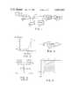
- FIG. 1illustrates in a block diagram a telephone subscriber line including at each end of the line a low pass filter for separating voice frequency signals from higher frequency data signals on the line;
- FIG. 2illustrates an attenuation versus frequency characteristic of the low pass filter
- FIG. 3is an equivalent circuit of the connections of the low pass filter
- FIG. 4illustrates a low pass filter designed in accordance with the prior art
- FIG. 5is a graph
- FIG. 6is an illustration of filter responses in the pass band, with reference to which the disadvantages of the prior art low pass filter and the advantages of a low pass filter according to this invention are explained;
- FIGS. 7 and 8illustrate two alternative forms of a low pass filter according to this invention.
- FIG. 9illustrates a modified form of the low pass filter of FIG. 8, also illustrating the form of a coupling network for coupling data signals to and from the telephone subscriber line.
- a subscriber's telephone 10is coupled to a telephone central office 11 via a conventional two-wire subscriber line 12.
- Modems 13 and 14are also connected to the subscriber line 12 for transmitting data via the subscriber line between the locations of the telephone 10 and the central office 11, at a frequency, of for example 21 kHz, which is above the voice frequency band.
- theseare coupled to the subscriber line 12 via low pass filters 15 and 16.
- FIG. 2illustrates the attenuation of a low pass filter as a function of frequency.
- Each of the filters 15 and 16is required to have a characteristic including a pass band up to a frequency fp in which the filter has a maximum attenuation ripple, or variation, Ap, and a stop band from a frequency fs in which the filter has a minimum attenuation As.
- fs21 kHz
- As60 dB
- fp3200 Hz
- Ap⁇ 0.1 dB relative to the attenuation at 1000 Hz.
- the low pass filter 15is effectively driven by a voltage source 17 in series with an impedance Z1 connected to an input port of the filter, and is loaded by an impedance Z2.
- the source 17 and impedance Z1correspond to the telephone 10, while the impedance Z2 corresponds to the subscriber line 12, both typically having nominal impedances of 600 ohms.
- This programis used in known manner, initially being supplied with the desired characteristic values and resistive termination impedances Z1 and Z2 to determine a transfer function of the filter, and from this and the desired configuration of the filter to derive the form of a filter which satisfies the characteristic values and which is matched to the resistive termination impedances Z1 and Z2.
- Thistypically results in the form of filter shown in FIG. 4, which is a 3rd order filter having series inductors 18, 19 and a shunt path including a capacitor 20 in series with an inductor 21.
- the elements 18 to 21have values of 50.41 mH, 50.41 mH, 95.79 nF, and 0.497 mH respectively, as indicated in FIG. 4.
- FIG. 5is a complex impedance graph, for a frequency of 3000 Hz, illustrating the resistance R and reactance X of various points A to E.
- the point Aof zero reactance and 600 ohm resistance, corresponds to the nominal termination impedances Z1 and Z2 for which the filter of FIG. 4 is designed as described above.
- the subscriber line 12is in practice not a purely resistive and accurately known impedance but a capacitive impedance which typically falls anywhere within the shaded area of FIG. 5, bounded by the points B, C, D, and E.
- FIG. 6illustrates the attenuation of the filter of FIG. 4 in its passband up to 3000 Hz, relative to its attenuation at 1000 Hz, when the filter of FIG. 4 is terminated with impedances corresponding to each of the points A to E in FIG. 5.
- the filter attenuation in the passbandchanges as shown by the curves B to E respectively in FIG. 6, becoming much more variable so that the ripple greatly exceeds the design limit Ap.
- a filter such as that of FIG. 4, designed according to the prior artcan not be used with arbitrary subscriber lines 12 whose impedances fall anywhere within the shaded area of FIG. 5, if the design characteristics of the filter are to be satisfied.
- prior art filtersmust be individually designed for and/or matched to the subscriber lines with which they are to be used, in order to meet the required design characteristics.
- This individual design or matchingis a great disadvantage because it is costly and time consuming and the filters are not readily interchangeable.
- much more complex and costly adaptive filters or buffered filtersmust be used.
- this disadvantageis very largely avoided or substantially eliminated by designing each of the low pass filters 15 and 16 in accordance with the desired characteristics already discussed, but with the additional constraint that the quantities
- Z1 and Z2are the nominal input and output, respectively, termination impedances of the filter as shown in FIG. 3 (which may in this case be complex impedances rather than purely resistive impedances as in the prior art)
- Zinis the input impedance of the filter at its input port
- Zoutis the output impedance of the filter at its output port.
- the desired characteristic values fs, As, fp, and Ap and the nominal termination impedances Z1 and Z2are used in the computer design program FILSYN to determine the transfer function of the filter, and from this and the desired configuration of the filter to determine a form of filter as in the prior art.
- the resultis a 3rd order filter as already described.
- This determined form of filteris then optimized, preferably using the computer aided design program SCAMPER (see Telesis, Volume 7, Number 3, 1980, pages 2 to 9, published by Bell-Northern Research Ltd.), to provide the best possible filter response.
- the program SCAMPERis used with the additional constraint imposed in this program that the sum
- the SCAMPER programindicates that this can not be achieved with the number of variables provided by the determined form of the 3rd order filter. Accordingly, the FILSYN program is used again with the desired characteristic values and the nominal termination impedances with the additional requirement (not necessary in the prior art) that the filter be a higher order filter, e.g. a 5th order filter.
- a more restrictive pass band ripple Apcould be imposed upon the filter design using the FILSYN program, with a similar result.
- the resulting determined form of 5th order filteris then optimized using the SCAMPER program, again with the additional constraint imposed that the sum
- the resulting 5th order filteris typically as shown in FIG. 7, comprising shunt capacitors 22, 23, series inductors 24, 25, and a shunt path including a capacitor 26 in series with an inductor 27. Using the characteristic values and nominal terminating impedances discussed above and as used to determine the filter of FIG.
- the elements 22 to 27have values of 30.88 nF, 30.88 nF, 24.96 mH, 24.96 mH, 30.54 nF, and 0.399 mH respectively, as indicated in FIG. 7.
- the filter of FIG. 7may be modified by providing the series inductances equally in the two wires of the filter, thereby balancing the filter.
- the series inductancesare provided by four 12.48 mH inductors.
- a solid line 28illustrates the attenuation of the filter of FIG. 7 or 8, relative to its attenuation at a frequency of 1000 Hz, in the pass band up to 3000 Hz.
- this attenuationis substantially the same throughout the passband regardless of the complex impedance, within the quadrant of the complex impedance graph of FIG. 5, with which the filter is terminated.
- the line 28 in FIG. 6represents the filter attenuation in the passband for all of the points A to E in FIG. 5.
- the filter of FIG. 7 or 8can be used as each of the low pass filters 15 and 16 in FIG. 1 to provide the desired filter characteristics regardless of the nature of the particular subscriber line 12 which is used.
- this relatively simple filtercan be used interchangeably, without requiring expensive buffering or adjustment, on arbitrary subscriber lines 12, the desired low pass filter characteristics always being satisfied.
- FIG. 9illustrates a modified form of the low pass filter of FIG. 8 and also illustrates the form of a coupling network which meets these requirements. This arrangement is described in greater detail in, and forms the subject of, the application by R.T. Carsten et al. already referred to and incorporated herein by reference.
- the arrangement shown in FIG. 9serves to couple frequency-shift-keyed (FSK) data at a center frequency of 36 kHz from the modem 14 at the central office end of the line 12 to the line for transmission to the subscriber end modem 13, and serves to couple FSK data at a center frequency of 22 kHz received from the modem 13 via the line 12 to the modem 14.
- FSKfrequency-shift-keyed
- the low pass filtercomprising the components 22 to 27 is the same as described above with reference to FIGS. 7 and 8, except for the arrangement of the inductors 24 and 25 and the connections of the shunt capacitor 22 on the line 12 side of the filter.
- the components of the filterhave the same reactances as described above to provide the same filter characteristics.
- each of the inductors 24 and 25is divided equally between the two wires of the filter.
- the divided inductances of each inductor 24 and 25are coupled with phases as indicated by dots in FIG. 9, to provide improved longitudinal balance and to reduce their physical size.
- each inductor 24 and 25are bifilar wound, the inductance of each individual coil, measured with the coil to which it is coupled open-circuit, being 6.24 mH to provide the desired total inductance of 24.96 mH for each inductor.
- the windingsare phased as shown by dots in FIG. 9, to couple between unbalanced signals on a line 29 and balanced signals on the line 12.
- the transformer 28has a turns ratio from the primary to the secondaries of 2.11 to 1.
- the primary winding 28cis coupled to the line 29 via a resistor 30, which together with series-connected oppositely-poled zener diodes 31 coupled between the line 29 and circuit ground provide lightning protection for the circuitry coupled to the line 29.
- FSK data from the modem 14 at the 22 kHz center frequencyis conducted from a wire 32 to the line 29 via a 22 kHz passive bandpass filter and amplifier 33, a parallel resonant circuit comprising an inductor 34 and a capacitor 35, and a series resistor 36.
- This datais coupled from the line 29 to the line 12 via the resistor 30 and the transformer 28.
- FSK data received via the line 12 at the 36 kHz center frequencyis coupled to the line 29 via the transformer 28 and the resistor 30.
- This datais coupled from the line 29 to a wire 37, leading to the modem 14, via a series resistor 38, a shunt resistor 39, and a 36 kHz passive bandpass filter 40.
- a parallel resonant circuitcomprising an inductor 41 and a capacitor 42 is also connected between the line 29 and circuit ground. The magnitudes of the various components 34, 35, 36, 38, 39, 41, and 42 are shown in FIG. 9.
- the inductor 34 and the capacitor 35are parallel resonant at 36 kHz, so that they inhibit any 36 kHz component of the 22 kHz transmit data signals reaching the line 29 and thence being coupled to the wire 37.
- the inductor 41 and the capacitor 42are parallel resonant at 22 kHz, so that they are an effective open circuit at this frequency and do not shunt the transmit data signals to ground.
- the inductor 34, and the capacitor 22 of the low pass filter, as reflected through the transformer 28,are series resonant at 22 kHz. Consequently the transmit data signals at this frequency are coupled from the wire 32 to the line 12 without significant attenuation by the low pass filter.
- the series resistor 36reduces impulse noise effects on the output of the filter and amplifier 33.
- Receive data signals on the line 12 at a frequency of 36 kHzare coupled via the transformer 28 to the line 29, and thence via the filter 40 to the wire 37.
- these signalsare attenuated by the parallel resonant circuit comprising the inductor 41 and the capacitor 42, and by the voltage divider formed by the resistors 38 and 39 which serve to properly terminate the filter 40 and avoid unduly loading the line 12, this attenuation can be compensated for by subsequent amplification of the signals.
- the attenuation of the receive data signals by the parallel resonant circuit 41, 42could be reduced by providing a more complicated circuit which is parallel resonant at 36 kHz as well as at 22 kHz.
- the data coupling network at the subscriber end of the line 12can be similar to that described above and shown in FIG. 9, except that it serves to receive FSK data at 22 kHz and to transmit FSK data at 36 kHz.
- this networkcan include a 2.81 mH series inductor in the transmit data signal path to series resonate with the relevant 30.88 nF filter capacitor at 36 kHz, this inductor corresponding to the inductor 34 in FIG. 9.
- the higher transmit frequency and the lower receive frequencyin this case precludes using simply a parallel capacitor, corresponding to the capacitor 35 in FIG. 9, to trap transmit data signal components at the receive frequency, but these can be separately filtered, for example using an active transmit filter.
- the parallel resonant circuit, corresponding to the circuit 41, 42 in FIG. 9,can be constituted by a 4.6 mH inductor in parallel with a 4.12 nF capacitor to resonate at the transmit frequency of 36 kHz.
- the inventionhas been described in its application to a low pass filter for connection to a telephone subscriber line, it is not limited in its application thereto, nor is it limited to the types of filter to which it may be applied.
- the principles of the inventioncan be applied to other than low pass filters, e.g. to high pass and band pass filters, for connection to telephone subscriber lines, and can be applied to the design of low pass or other filters for use in other applications where variable or unknown termination impedances may be present.
- each modemcould be designed in accordance with the invention to have the sum
- the form and order of the filtermay vary from those described above, and in any event the particular impedances of the reactive components of the filter will be dependent upon the particular filter characteristics which are desired.
- the filter design described aboveuses the computer programs FILSYN and SCAMPER to determine the impedances of the reactive components of the filter, this being the preferred manner of effecting the filter design, the invention is not limited in this respect and other computer or manual design techniques may be used instead. Accordingly, the invention is not limited to the preferred embodiments described above, and numerous changes may be made without departing from the scope of the invention, which is defined in the claims.
Landscapes
- Engineering & Computer Science (AREA)
- Power Engineering (AREA)
- Computer Networks & Wireless Communication (AREA)
- Signal Processing (AREA)
- Filters And Equalizers (AREA)
Abstract
Description
Claims (9)
Priority Applications (1)
| Application Number | Priority Date | Filing Date | Title |
|---|---|---|---|
| US06/333,665US4443662A (en) | 1981-04-10 | 1981-12-23 | Filters comprising reactive components, and a method of determining impedances thereof |
Applications Claiming Priority (2)
| Application Number | Priority Date | Filing Date | Title |
|---|---|---|---|
| US25292581A | 1981-04-10 | 1981-04-10 | |
| US06/333,665US4443662A (en) | 1981-04-10 | 1981-12-23 | Filters comprising reactive components, and a method of determining impedances thereof |
Related Parent Applications (1)
| Application Number | Title | Priority Date | Filing Date |
|---|---|---|---|
| US25292581AContinuation-In-Part | 1981-04-10 | 1981-04-10 |
Publications (1)
| Publication Number | Publication Date |
|---|---|
| US4443662Atrue US4443662A (en) | 1984-04-17 |
Family
ID=26942795
Family Applications (1)
| Application Number | Title | Priority Date | Filing Date |
|---|---|---|---|
| US06/333,665Expired - LifetimeUS4443662A (en) | 1981-04-10 | 1981-12-23 | Filters comprising reactive components, and a method of determining impedances thereof |
Country Status (1)
| Country | Link |
|---|---|
| US (1) | US4443662A (en) |
Cited By (37)
| Publication number | Priority date | Publication date | Assignee | Title |
|---|---|---|---|---|
| US4764922A (en)* | 1985-08-21 | 1988-08-16 | Siemens Aktiengesellschaft | Data terminal interface circuit to a telephone transmission line |
| US4985892A (en)* | 1984-06-01 | 1991-01-15 | Xerox Corporation | Baseband local area network using ordinary telephone wiring |
| US5150365A (en)* | 1986-11-18 | 1992-09-22 | Hitachi, Ltd. | Communication system for coexistent base band and broad band signals |
| US5301208A (en)* | 1992-02-25 | 1994-04-05 | The United States Of America As Represented By The Secretary Of The Air Force | Transformer bus coupler |
| US5404388A (en)* | 1993-03-03 | 1995-04-04 | Northern Telecom Limited | Digital measurement of amplitude and phase of a sinusoidal signal and detection of load coil based on said measurement |
| EP0677938A1 (en)* | 1994-04-14 | 1995-10-18 | ALCATEL BELL Naamloze Vennootschap | Signal coupler |
| US20010019608A1 (en)* | 2000-01-27 | 2001-09-06 | Bengt Gustav Lofmark | Method and arrangement for filtering of signals |
| US20020071531A1 (en)* | 1989-07-14 | 2002-06-13 | Inline Connections Corporation, A Virginia Corporation | Video transmission and control system utilizing internal telephone lines |
| US20030031312A1 (en)* | 1999-02-15 | 2003-02-13 | Nokia Networks Oy | Multiplexing and demultiplexing of narrowband and broadband services in a transmission connection |
| US20030147513A1 (en)* | 1999-06-11 | 2003-08-07 | Goodman David D. | High-speed data communication over a residential telephone wiring network |
| US20030165220A1 (en)* | 1989-07-14 | 2003-09-04 | Goodman David D. | Distributed splitter for data transmission over twisted wire pairs |
| US20040199909A1 (en)* | 1999-07-27 | 2004-10-07 | Inline Connection Corporation | Universal serial bus adapter with automatic installation |
| US20040230710A1 (en)* | 1999-07-27 | 2004-11-18 | Inline Connection Corporation | System and method of automatic installation of computer peripherals |
| US20050047431A1 (en)* | 2001-10-11 | 2005-03-03 | Serconet Ltd. | Outlet with analog signal adapter, a method for use thereof and a network using said outlet |
| US20050249245A1 (en)* | 2004-05-06 | 2005-11-10 | Serconet Ltd. | System and method for carrying a wireless based signal over wiring |
| US20050277328A1 (en)* | 2000-04-19 | 2005-12-15 | Serconet Ltd | Network combining wired and non-wired segments |
| WO2006018376A3 (en)* | 2004-08-11 | 2006-07-27 | Bsh Bosch Siemens Hausgeraete | Circuit arrangement for suppressing interference signals in the receive branch of a modem of a household appliance |
| US20060268487A1 (en)* | 2002-03-14 | 2006-11-30 | Ambient Corporation | Protecting medium voltage inductive coupled device from electrical transients |
| US20070173202A1 (en)* | 2006-01-11 | 2007-07-26 | Serconet Ltd. | Apparatus and method for frequency shifting of a wireless signal and systems using frequency shifting |
| US7274688B2 (en) | 2000-04-18 | 2007-09-25 | Serconet Ltd. | Telephone communication system over a single telephone line |
| US7317793B2 (en) | 2003-01-30 | 2008-01-08 | Serconet Ltd | Method and system for providing DC power on local telephone lines |
| US7483524B2 (en) | 1999-07-20 | 2009-01-27 | Serconet, Ltd | Network for telephony and data communication |
| US7522714B2 (en) | 2000-03-20 | 2009-04-21 | Serconet Ltd. | Telephone outlet for implementing a local area network over telephone lines and a local area network using such outlets |
| US7542554B2 (en) | 2001-07-05 | 2009-06-02 | Serconet, Ltd | Telephone outlet with packet telephony adapter, and a network using same |
| US7686653B2 (en) | 2003-09-07 | 2010-03-30 | Mosaid Technologies Incorporated | Modular outlet |
| US20100099451A1 (en)* | 2008-06-20 | 2010-04-22 | Mobileaccess Networks Ltd. | Method and System for Real Time Control of an Active Antenna Over a Distributed Antenna System |
| US20100244983A1 (en)* | 2009-03-31 | 2010-09-30 | 2Wire, Inc. | Constant impedance filter |
| US20100309931A1 (en)* | 2007-10-22 | 2010-12-09 | Mobileaccess Networks Ltd. | Communication system using low bandwidth wires |
| US7873058B2 (en) | 2004-11-08 | 2011-01-18 | Mosaid Technologies Incorporated | Outlet with analog signal adapter, a method for use thereof and a network using said outlet |
| US20110170476A1 (en)* | 2009-02-08 | 2011-07-14 | Mobileaccess Networks Ltd. | Communication system using cables carrying ethernet signals |
| US8005206B1 (en) | 2007-03-15 | 2011-08-23 | Bh Electronics, Inc. | VDSL splitter |
| US8238328B2 (en) | 2003-03-13 | 2012-08-07 | Mosaid Technologies Incorporated | Telephone system having multiple distinct sources and accessories therefor |
| US8270430B2 (en) | 1998-07-28 | 2012-09-18 | Mosaid Technologies Incorporated | Local area network of serial intelligent cells |
| US9184960B1 (en) | 2014-09-25 | 2015-11-10 | Corning Optical Communications Wireless Ltd | Frequency shifting a communications signal(s) in a multi-frequency distributed antenna system (DAS) to avoid or reduce frequency interference |
| US9338823B2 (en) | 2012-03-23 | 2016-05-10 | Corning Optical Communications Wireless Ltd | Radio-frequency integrated circuit (RFIC) chip(s) for providing distributed antenna system functionalities, and related components, systems, and methods |
| US10986165B2 (en) | 2004-01-13 | 2021-04-20 | May Patents Ltd. | Information device |
| US20220399717A1 (en)* | 2021-06-11 | 2022-12-15 | Semiconductor Components Industries, Llc | Interference filter and electrostatic discharge / electrical surge protection circuit and device |
Citations (3)
| Publication number | Priority date | Publication date | Assignee | Title |
|---|---|---|---|---|
| US1752461A (en)* | 1925-07-24 | 1930-04-01 | Western Electric Co | Transmission network |
| US3132313A (en)* | 1959-08-13 | 1964-05-05 | Alford Andrew | Impedance matching filter |
| US3987375A (en)* | 1975-03-25 | 1976-10-19 | Stromberg-Carlson Corporation | Transmission bridge exhibiting reduced distortion |
- 1981
- 1981-12-23USUS06/333,665patent/US4443662A/ennot_activeExpired - Lifetime
Patent Citations (3)
| Publication number | Priority date | Publication date | Assignee | Title |
|---|---|---|---|---|
| US1752461A (en)* | 1925-07-24 | 1930-04-01 | Western Electric Co | Transmission network |
| US3132313A (en)* | 1959-08-13 | 1964-05-05 | Alford Andrew | Impedance matching filter |
| US3987375A (en)* | 1975-03-25 | 1976-10-19 | Stromberg-Carlson Corporation | Transmission bridge exhibiting reduced distortion |
Non-Patent Citations (8)
| Title |
|---|
| "FILSYN-A General Purpose Filter Synthesis Program" by G. Szentirmai, Proc. IEEE, vol. 65, No. 10, Oct. 1977, pp. 1443 to 1458. |
| "SCAMPER"-Telesis, vol. 7, No. 3, 1980, pp. 2 to 9. |
| Electrical Communication , vol. 36, No. 1, 1959, pp. 3 26, Gaussian Response Filter Design , Dishal.* |
| Electrical Communication, vol. 36, No. 1, 1959, pp. 3-26, "Gaussian Response Filter Design", Dishal. |
| FILSYN A General Purpose Filter Synthesis Program by G. Szentirmai, Proc. IEEE, vol. 65, No. 10, Oct. 1977, pp. 1443 to 1458.* |
| IRE Transactions on Circuit Theory , pp. 284 327, Dec. 1958, On The Design of Filters by Synthesis , Saal and Ulbrich.* |
| IRE Transactions on Circuit Theory, pp. 284-327, Dec. 1958, "On The Design of Filters by Synthesis", Saal and Ulbrich. |
| SCAMPER Telesis, vol. 7, No. 3, 1980, pp. 2 to 9.* |
Cited By (110)
| Publication number | Priority date | Publication date | Assignee | Title |
|---|---|---|---|---|
| US4985892A (en)* | 1984-06-01 | 1991-01-15 | Xerox Corporation | Baseband local area network using ordinary telephone wiring |
| US4764922A (en)* | 1985-08-21 | 1988-08-16 | Siemens Aktiengesellschaft | Data terminal interface circuit to a telephone transmission line |
| US5150365A (en)* | 1986-11-18 | 1992-09-22 | Hitachi, Ltd. | Communication system for coexistent base band and broad band signals |
| US6970537B2 (en) | 1989-07-14 | 2005-11-29 | Inline Connection Corporation | Video transmission and control system utilizing internal telephone lines |
| US20050117722A1 (en)* | 1989-07-14 | 2005-06-02 | Inline Connection Corporation | Video transmission and control system utilizing internal telephone lines |
| US20050117721A1 (en)* | 1989-07-14 | 2005-06-02 | Goodman David D. | Video transmission and control system utilizing internal telephone lines |
| US7577240B2 (en) | 1989-07-14 | 2009-08-18 | Inline Connection Corporation | Two-way communication over a single transmission line between one or more information sources and a group of telephones, computers, and televisions |
| US7227932B2 (en) | 1989-07-14 | 2007-06-05 | Inline Connection Corporation | Multi-band data over voice communication system and method |
| US20020071531A1 (en)* | 1989-07-14 | 2002-06-13 | Inline Connections Corporation, A Virginia Corporation | Video transmission and control system utilizing internal telephone lines |
| US7224780B2 (en) | 1989-07-14 | 2007-05-29 | Inline Connection Corporation | Multichannel transceiver using redundant encoding and strategic channel spacing |
| US7149289B2 (en) | 1989-07-14 | 2006-12-12 | Inline Connection Corporation | Interactive data over voice communication system and method |
| US20030165220A1 (en)* | 1989-07-14 | 2003-09-04 | Goodman David D. | Distributed splitter for data transmission over twisted wire pairs |
| US20080284840A1 (en)* | 1991-12-05 | 2008-11-20 | Inline Connection Corporation | Method, System and Apparatus for Voice and Data Transmission Over A Conductive Path |
| US5301208A (en)* | 1992-02-25 | 1994-04-05 | The United States Of America As Represented By The Secretary Of The Air Force | Transformer bus coupler |
| US5404388A (en)* | 1993-03-03 | 1995-04-04 | Northern Telecom Limited | Digital measurement of amplitude and phase of a sinusoidal signal and detection of load coil based on said measurement |
| US5627501A (en)* | 1994-04-14 | 1997-05-06 | Alcatel N.V. | Signal coupler with automatic common line attenuation compensation |
| EP0677938A1 (en)* | 1994-04-14 | 1995-10-18 | ALCATEL BELL Naamloze Vennootschap | Signal coupler |
| US8270430B2 (en) | 1998-07-28 | 2012-09-18 | Mosaid Technologies Incorporated | Local area network of serial intelligent cells |
| US8885659B2 (en) | 1998-07-28 | 2014-11-11 | Conversant Intellectual Property Management Incorporated | Local area network of serial intelligent cells |
| US8885660B2 (en) | 1998-07-28 | 2014-11-11 | Conversant Intellectual Property Management Incorporated | Local area network of serial intelligent cells |
| US8867523B2 (en) | 1998-07-28 | 2014-10-21 | Conversant Intellectual Property Management Incorporated | Local area network of serial intelligent cells |
| US8908673B2 (en) | 1998-07-28 | 2014-12-09 | Conversant Intellectual Property Management Incorporated | Local area network of serial intelligent cells |
| US8325636B2 (en) | 1998-07-28 | 2012-12-04 | Mosaid Technologies Incorporated | Local area network of serial intelligent cells |
| US6937719B2 (en) | 1999-02-15 | 2005-08-30 | Nokia Networks Oy | Multiplexing and demultiplexing of narrowband and broadband services in a transmission connection |
| US20030031312A1 (en)* | 1999-02-15 | 2003-02-13 | Nokia Networks Oy | Multiplexing and demultiplexing of narrowband and broadband services in a transmission connection |
| US7145990B2 (en) | 1999-06-11 | 2006-12-05 | Inline Connection Corporation | High-speed data communication over a residential telephone wiring network |
| US20030147513A1 (en)* | 1999-06-11 | 2003-08-07 | Goodman David D. | High-speed data communication over a residential telephone wiring network |
| US7483524B2 (en) | 1999-07-20 | 2009-01-27 | Serconet, Ltd | Network for telephony and data communication |
| US8929523B2 (en) | 1999-07-20 | 2015-01-06 | Conversant Intellectual Property Management Inc. | Network for telephony and data communication |
| US7522713B2 (en) | 1999-07-20 | 2009-04-21 | Serconet, Ltd. | Network for telephony and data communication |
| US7492875B2 (en) | 1999-07-20 | 2009-02-17 | Serconet, Ltd. | Network for telephony and data communication |
| US8351582B2 (en) | 1999-07-20 | 2013-01-08 | Mosaid Technologies Incorporated | Network for telephony and data communication |
| US20040199909A1 (en)* | 1999-07-27 | 2004-10-07 | Inline Connection Corporation | Universal serial bus adapter with automatic installation |
| US20040230710A1 (en)* | 1999-07-27 | 2004-11-18 | Inline Connection Corporation | System and method of automatic installation of computer peripherals |
| US20010019608A1 (en)* | 2000-01-27 | 2001-09-06 | Bengt Gustav Lofmark | Method and arrangement for filtering of signals |
| US7447305B2 (en) | 2000-01-27 | 2008-11-04 | Telefonaktiebolaget Lm Ericsson (Publ) | Method and arrangement for filtering of signals |
| US8363797B2 (en) | 2000-03-20 | 2013-01-29 | Mosaid Technologies Incorporated | Telephone outlet for implementing a local area network over telephone lines and a local area network using such outlets |
| US7715534B2 (en) | 2000-03-20 | 2010-05-11 | Mosaid Technologies Incorporated | Telephone outlet for implementing a local area network over telephone lines and a local area network using such outlets |
| US8855277B2 (en) | 2000-03-20 | 2014-10-07 | Conversant Intellectual Property Managment Incorporated | Telephone outlet for implementing a local area network over telephone lines and a local area network using such outlets |
| US7522714B2 (en) | 2000-03-20 | 2009-04-21 | Serconet Ltd. | Telephone outlet for implementing a local area network over telephone lines and a local area network using such outlets |
| US7466722B2 (en) | 2000-04-18 | 2008-12-16 | Serconet Ltd | Telephone communication system over a single telephone line |
| US8559422B2 (en) | 2000-04-18 | 2013-10-15 | Mosaid Technologies Incorporated | Telephone communication system over a single telephone line |
| US20080043646A1 (en)* | 2000-04-18 | 2008-02-21 | Serconet Ltd. | Telephone communication system over a single telephone line |
| US7274688B2 (en) | 2000-04-18 | 2007-09-25 | Serconet Ltd. | Telephone communication system over a single telephone line |
| US8000349B2 (en) | 2000-04-18 | 2011-08-16 | Mosaid Technologies Incorporated | Telephone communication system over a single telephone line |
| US7593394B2 (en) | 2000-04-18 | 2009-09-22 | Mosaid Technologies Incorporated | Telephone communication system over a single telephone line |
| US7397791B2 (en) | 2000-04-18 | 2008-07-08 | Serconet, Ltd. | Telephone communication system over a single telephone line |
| US8223800B2 (en) | 2000-04-18 | 2012-07-17 | Mosaid Technologies Incorporated | Telephone communication system over a single telephone line |
| US8873586B2 (en) | 2000-04-19 | 2014-10-28 | Conversant Intellectual Property Management Incorporated | Network combining wired and non-wired segments |
| US8848725B2 (en) | 2000-04-19 | 2014-09-30 | Conversant Intellectual Property Management Incorporated | Network combining wired and non-wired segments |
| US8982904B2 (en) | 2000-04-19 | 2015-03-17 | Conversant Intellectual Property Management Inc. | Network combining wired and non-wired segments |
| US8873575B2 (en) | 2000-04-19 | 2014-10-28 | Conversant Intellectual Property Management Incorporated | Network combining wired and non-wired segments |
| US8867506B2 (en) | 2000-04-19 | 2014-10-21 | Conversant Intellectual Property Management Incorporated | Network combining wired and non-wired segments |
| US7633966B2 (en) | 2000-04-19 | 2009-12-15 | Mosaid Technologies Incorporated | Network combining wired and non-wired segments |
| US20050277328A1 (en)* | 2000-04-19 | 2005-12-15 | Serconet Ltd | Network combining wired and non-wired segments |
| US7680255B2 (en) | 2001-07-05 | 2010-03-16 | Mosaid Technologies Incorporated | Telephone outlet with packet telephony adaptor, and a network using same |
| US7769030B2 (en) | 2001-07-05 | 2010-08-03 | Mosaid Technologies Incorporated | Telephone outlet with packet telephony adapter, and a network using same |
| US8472593B2 (en) | 2001-07-05 | 2013-06-25 | Mosaid Technologies Incorporated | Telephone outlet with packet telephony adaptor, and a network using same |
| US7542554B2 (en) | 2001-07-05 | 2009-06-02 | Serconet, Ltd | Telephone outlet with packet telephony adapter, and a network using same |
| US8761186B2 (en) | 2001-07-05 | 2014-06-24 | Conversant Intellectual Property Management Incorporated | Telephone outlet with packet telephony adapter, and a network using same |
| US20050047431A1 (en)* | 2001-10-11 | 2005-03-03 | Serconet Ltd. | Outlet with analog signal adapter, a method for use thereof and a network using said outlet |
| US7436842B2 (en) | 2001-10-11 | 2008-10-14 | Serconet Ltd. | Outlet with analog signal adapter, a method for use thereof and a network using said outlet |
| US7889720B2 (en) | 2001-10-11 | 2011-02-15 | Mosaid Technologies Incorporated | Outlet with analog signal adapter, a method for use thereof and a network using said outlet |
| US7860084B2 (en) | 2001-10-11 | 2010-12-28 | Mosaid Technologies Incorporated | Outlet with analog signal adapter, a method for use thereof and a network using said outlet |
| US7953071B2 (en) | 2001-10-11 | 2011-05-31 | Mosaid Technologies Incorporated | Outlet with analog signal adapter, a method for use thereof and a network using said outlet |
| US7453895B2 (en) | 2001-10-11 | 2008-11-18 | Serconet Ltd | Outlet with analog signal adapter, a method for use thereof and a network using said outlet |
| US7529073B2 (en)* | 2002-03-14 | 2009-05-05 | Ambient Corporation | Protecting medium voltage inductive coupled device from electrical transients |
| US20060268487A1 (en)* | 2002-03-14 | 2006-11-30 | Ambient Corporation | Protecting medium voltage inductive coupled device from electrical transients |
| US8787562B2 (en) | 2003-01-30 | 2014-07-22 | Conversant Intellectual Property Management Inc. | Method and system for providing DC power on local telephone lines |
| US7317793B2 (en) | 2003-01-30 | 2008-01-08 | Serconet Ltd | Method and system for providing DC power on local telephone lines |
| US8107618B2 (en) | 2003-01-30 | 2012-01-31 | Mosaid Technologies Incorporated | Method and system for providing DC power on local telephone lines |
| US7702095B2 (en) | 2003-01-30 | 2010-04-20 | Mosaid Technologies Incorporated | Method and system for providing DC power on local telephone lines |
| US8238328B2 (en) | 2003-03-13 | 2012-08-07 | Mosaid Technologies Incorporated | Telephone system having multiple distinct sources and accessories therefor |
| US7867035B2 (en) | 2003-07-09 | 2011-01-11 | Mosaid Technologies Incorporated | Modular outlet |
| US8591264B2 (en) | 2003-09-07 | 2013-11-26 | Mosaid Technologies Incorporated | Modular outlet |
| US8235755B2 (en) | 2003-09-07 | 2012-08-07 | Mosaid Technologies Incorporated | Modular outlet |
| US8360810B2 (en) | 2003-09-07 | 2013-01-29 | Mosaid Technologies Incorporated | Modular outlet |
| US7686653B2 (en) | 2003-09-07 | 2010-03-30 | Mosaid Technologies Incorporated | Modular outlet |
| US8092258B2 (en) | 2003-09-07 | 2012-01-10 | Mosaid Technologies Incorporated | Modular outlet |
| US10986165B2 (en) | 2004-01-13 | 2021-04-20 | May Patents Ltd. | Information device |
| US11095708B2 (en) | 2004-01-13 | 2021-08-17 | May Patents Ltd. | Information device |
| US11032353B2 (en) | 2004-01-13 | 2021-06-08 | May Patents Ltd. | Information device |
| US10986164B2 (en) | 2004-01-13 | 2021-04-20 | May Patents Ltd. | Information device |
| US8325759B2 (en) | 2004-05-06 | 2012-12-04 | Corning Mobileaccess Ltd | System and method for carrying a wireless based signal over wiring |
| US20050249245A1 (en)* | 2004-05-06 | 2005-11-10 | Serconet Ltd. | System and method for carrying a wireless based signal over wiring |
| WO2006018376A3 (en)* | 2004-08-11 | 2006-07-27 | Bsh Bosch Siemens Hausgeraete | Circuit arrangement for suppressing interference signals in the receive branch of a modem of a household appliance |
| US7873058B2 (en) | 2004-11-08 | 2011-01-18 | Mosaid Technologies Incorporated | Outlet with analog signal adapter, a method for use thereof and a network using said outlet |
| US7587001B2 (en) | 2006-01-11 | 2009-09-08 | Serconet Ltd. | Apparatus and method for frequency shifting of a wireless signal and systems using frequency shifting |
| US7813451B2 (en) | 2006-01-11 | 2010-10-12 | Mobileaccess Networks Ltd. | Apparatus and method for frequency shifting of a wireless signal and systems using frequency shifting |
| US20070173202A1 (en)* | 2006-01-11 | 2007-07-26 | Serconet Ltd. | Apparatus and method for frequency shifting of a wireless signal and systems using frequency shifting |
| US8184681B2 (en) | 2006-01-11 | 2012-05-22 | Corning Mobileaccess Ltd | Apparatus and method for frequency shifting of a wireless signal and systems using frequency shifting |
| US8005206B1 (en) | 2007-03-15 | 2011-08-23 | Bh Electronics, Inc. | VDSL splitter |
| US20100309931A1 (en)* | 2007-10-22 | 2010-12-09 | Mobileaccess Networks Ltd. | Communication system using low bandwidth wires |
| US8594133B2 (en) | 2007-10-22 | 2013-11-26 | Corning Mobileaccess Ltd. | Communication system using low bandwidth wires |
| US9813229B2 (en) | 2007-10-22 | 2017-11-07 | Corning Optical Communications Wireless Ltd | Communication system using low bandwidth wires |
| US9549301B2 (en) | 2007-12-17 | 2017-01-17 | Corning Optical Communications Wireless Ltd | Method and system for real time control of an active antenna over a distributed antenna system |
| US20100099451A1 (en)* | 2008-06-20 | 2010-04-22 | Mobileaccess Networks Ltd. | Method and System for Real Time Control of an Active Antenna Over a Distributed Antenna System |
| US8175649B2 (en) | 2008-06-20 | 2012-05-08 | Corning Mobileaccess Ltd | Method and system for real time control of an active antenna over a distributed antenna system |
| US20110170476A1 (en)* | 2009-02-08 | 2011-07-14 | Mobileaccess Networks Ltd. | Communication system using cables carrying ethernet signals |
| US8897215B2 (en) | 2009-02-08 | 2014-11-25 | Corning Optical Communications Wireless Ltd | Communication system using cables carrying ethernet signals |
| US8154362B2 (en)* | 2009-03-31 | 2012-04-10 | 2Wire, Inc. | Constant impedance filter |
| US20100244983A1 (en)* | 2009-03-31 | 2010-09-30 | 2Wire, Inc. | Constant impedance filter |
| US9338823B2 (en) | 2012-03-23 | 2016-05-10 | Corning Optical Communications Wireless Ltd | Radio-frequency integrated circuit (RFIC) chip(s) for providing distributed antenna system functionalities, and related components, systems, and methods |
| US9948329B2 (en) | 2012-03-23 | 2018-04-17 | Corning Optical Communications Wireless, LTD | Radio-frequency integrated circuit (RFIC) chip(s) for providing distributed antenna system functionalities, and related components, systems, and methods |
| US10141959B2 (en) | 2012-03-23 | 2018-11-27 | Corning Optical Communications Wireless Ltd | Radio-frequency integrated circuit (RFIC) chip(s) for providing distributed antenna system functionalities, and related components, systems, and methods |
| US9515855B2 (en) | 2014-09-25 | 2016-12-06 | Corning Optical Communications Wireless Ltd | Frequency shifting a communications signal(s) in a multi-frequency distributed antenna system (DAS) to avoid or reduce frequency interference |
| US9253003B1 (en) | 2014-09-25 | 2016-02-02 | Corning Optical Communications Wireless Ltd | Frequency shifting a communications signal(S) in a multi-frequency distributed antenna system (DAS) to avoid or reduce frequency interference |
| US9184960B1 (en) | 2014-09-25 | 2015-11-10 | Corning Optical Communications Wireless Ltd | Frequency shifting a communications signal(s) in a multi-frequency distributed antenna system (DAS) to avoid or reduce frequency interference |
| US20220399717A1 (en)* | 2021-06-11 | 2022-12-15 | Semiconductor Components Industries, Llc | Interference filter and electrostatic discharge / electrical surge protection circuit and device |
| US12316105B2 (en)* | 2021-06-11 | 2025-05-27 | Semiconductor Components Industries, Llc | Interference filter and electrostatic discharge / electrical surge protection circuit and device |
Similar Documents
| Publication | Publication Date | Title |
|---|---|---|
| US4443662A (en) | Filters comprising reactive components, and a method of determining impedances thereof | |
| US4456985A (en) | Apparatus for coupling signals to or from a two-wire line | |
| US4456986A (en) | Apparatus for coupling signals to or from a two-wire line | |
| US4800344A (en) | Balun | |
| US4717896A (en) | Balun | |
| AU695672B2 (en) | Erasure detection in data streams | |
| US5705974A (en) | Power line communications system and coupling circuit for power line communications system | |
| US4764922A (en) | Data terminal interface circuit to a telephone transmission line | |
| US4878244A (en) | Electronic hybrid circuit | |
| US7386119B1 (en) | Filtered transmit cancellation in a full-duplex modem data access arrangement (DAA) | |
| US4074087A (en) | Bidirectional voice frequency repeater | |
| EP1006673B1 (en) | Load coil device | |
| EP0746117A2 (en) | Transmitter/receiver interface apparatus and method for a bi-directional transmission path | |
| EP0062442B1 (en) | Apparatus for coupling signals to or from a two-wire line | |
| US4003005A (en) | Bidirectional constant impedance low pass/high pass filter circuit | |
| US6917682B2 (en) | Method and device for echo cancelling | |
| EP0063414B1 (en) | Apparatus for coupling signals to or from a two-wire line | |
| CA1158789A (en) | Filters comprising reactive components, and a method of determining impedances thereof | |
| US6947529B2 (en) | DSL compatible load coil | |
| US7447305B2 (en) | Method and arrangement for filtering of signals | |
| US2029014A (en) | Wave transmission network | |
| US4899365A (en) | Apparatus and method for adaptive amplitude equalization | |
| CA1165914A (en) | Apparatus for coupling signals to or from a two-wire line | |
| CA1165913A (en) | Apparatus for coupling signals to or from a two-wire line | |
| WO1999067880A1 (en) | Transmission of power and signals over coaxial cable, twisted pair cable, and other electric cables |
Legal Events
| Date | Code | Title | Description |
|---|---|---|---|
| AS | Assignment | Owner name:NORTHERN TELECOM LIMITED, P. O. BOX 6123, MONTREAL Free format text:ASSIGNMENT OF ASSIGNORS INTEREST.;ASSIGNOR:BELL CANADA;REEL/FRAME:003973/0126 Effective date:19820126 Owner name:BELL CANADA, 1050 BEAVER HALL HILL, MONTREAL, QUEB Free format text:ASSIGNMENT OF ASSIGNORS INTEREST.;ASSIGNOR:BELL-NORTHERN RESEARCH LTD.;REEL/FRAME:003973/0125 Effective date:19811221 Owner name:BELL-NORTHERN RESEARCH LTD., P. O. BOX 3511, STATI Free format text:ASSIGNMENT OF ASSIGNORS INTEREST.;ASSIGNOR:NAKHLA, MICHAEL S.;REEL/FRAME:003973/0124 Effective date:19811218 | |
| STCF | Information on status: patent grant | Free format text:PATENTED CASE | |
| FEPP | Fee payment procedure | Free format text:PAYOR NUMBER ASSIGNED (ORIGINAL EVENT CODE: ASPN); ENTITY STATUS OF PATENT OWNER: LARGE ENTITY | |
| FPAY | Fee payment | Year of fee payment:4 | |
| FPAY | Fee payment | Year of fee payment:8 | |
| FPAY | Fee payment | Year of fee payment:12 | |
| AS | Assignment | Owner name:NORTEL NETWORKS CORPORATION, CANADA Free format text:CHANGE OF NAME;ASSIGNOR:NORTHERN TELECOM LIMITED;REEL/FRAME:010567/0001 Effective date:19990429 | |
| AS | Assignment | Owner name:NORTEL NETWORKS LIMITED, CANADA Free format text:CHANGE OF NAME;ASSIGNOR:NORTEL NETWORKS CORPORATION;REEL/FRAME:011195/0706 Effective date:20000830 Owner name:NORTEL NETWORKS LIMITED,CANADA Free format text:CHANGE OF NAME;ASSIGNOR:NORTEL NETWORKS CORPORATION;REEL/FRAME:011195/0706 Effective date:20000830 |