US4443407A - Analysis system - Google Patents
Analysis systemDownload PDFInfo
- Publication number
- US4443407A US4443407AUS06/391,102US39110282AUS4443407AUS 4443407 AUS4443407 AUS 4443407AUS 39110282 AUS39110282 AUS 39110282AUS 4443407 AUS4443407 AUS 4443407A
- Authority
- US
- United States
- Prior art keywords
- sensing
- cell
- sample
- port
- flow
- Prior art date
- Legal status (The legal status is an assumption and is not a legal conclusion. Google has not performed a legal analysis and makes no representation as to the accuracy of the status listed.)
- Expired - Fee Related
Links
- 238000004458analytical methodMethods0.000titleclaimsabstractdescription26
- 239000012530fluidSubstances0.000claimsabstractdescription61
- WYTGDNHDOZPMIW-RCBQFDQVSA-NalstonineNatural productsC1=CC2=C3C=CC=CC3=NC2=C2N1C[C@H]1[C@H](C)OC=C(C(=O)OC)[C@H]1C2WYTGDNHDOZPMIW-RCBQFDQVSA-N0.000claimsabstractdescription8
- 238000007789sealingMethods0.000claimsabstractdescription8
- 239000000523sampleSubstances0.000claimsdescription103
- 210000004027cellAnatomy0.000claimsdescription75
- 238000004891communicationMethods0.000claimsdescription10
- 239000007788liquidSubstances0.000claimsdescription8
- 230000003750conditioning effectEffects0.000claimsdescription6
- 239000012780transparent materialSubstances0.000claimsdescription5
- 239000003792electrolyteSubstances0.000claimsdescription4
- 238000002955isolationMethods0.000claimsdescription4
- 230000013011matingEffects0.000claimsdescription4
- 238000010438heat treatmentMethods0.000claimsdescription3
- 229910052751metalInorganic materials0.000claimsdescription3
- 239000002184metalSubstances0.000claimsdescription3
- 230000000087stabilizing effectEffects0.000claims2
- 239000007789gasSubstances0.000description15
- 239000008280bloodSubstances0.000description12
- 210000004369bloodAnatomy0.000description12
- CURLTUGMZLYLDI-UHFFFAOYSA-NCarbon dioxideChemical compoundO=C=OCURLTUGMZLYLDI-UHFFFAOYSA-N0.000description9
- 238000005070samplingMethods0.000description9
- 238000005259measurementMethods0.000description7
- 229910002092carbon dioxideInorganic materials0.000description5
- 229910052782aluminiumInorganic materials0.000description4
- XAGFODPZIPBFFR-UHFFFAOYSA-NaluminiumChemical compound[Al]XAGFODPZIPBFFR-UHFFFAOYSA-N0.000description4
- 239000001569carbon dioxideSubstances0.000description4
- 238000010586diagramMethods0.000description4
- 239000000243solutionSubstances0.000description4
- NIXOWILDQLNWCW-UHFFFAOYSA-Nacrylic acid groupChemical groupC(C=C)(=O)ONIXOWILDQLNWCW-UHFFFAOYSA-N0.000description3
- 239000000872bufferSubstances0.000description3
- 238000004868gas analysisMethods0.000description3
- XLYOFNOQVPJJNP-UHFFFAOYSA-NwaterSubstancesOXLYOFNOQVPJJNP-UHFFFAOYSA-N0.000description3
- QVGXLLKOCUKJST-UHFFFAOYSA-Natomic oxygenChemical compound[O]QVGXLLKOCUKJST-UHFFFAOYSA-N0.000description2
- 239000007853buffer solutionSubstances0.000description2
- 210000005056cell bodyAnatomy0.000description2
- 238000004140cleaningMethods0.000description2
- 239000000470constituentSubstances0.000description2
- 229920001971elastomerPolymers0.000description2
- 239000000806elastomerSubstances0.000description2
- 238000011067equilibrationMethods0.000description2
- 239000000463materialSubstances0.000description2
- 229910052760oxygenInorganic materials0.000description2
- 239000001301oxygenSubstances0.000description2
- 229910001220stainless steelInorganic materials0.000description2
- 239000010935stainless steelSubstances0.000description2
- 230000000712assemblyEffects0.000description1
- 238000000429assemblyMethods0.000description1
- 238000004159blood analysisMethods0.000description1
- 239000003914blood derivativeSubstances0.000description1
- 230000005587bubblingEffects0.000description1
- 239000011248coating agentSubstances0.000description1
- 238000000576coating methodMethods0.000description1
- 230000006835compressionEffects0.000description1
- 238000007906compressionMethods0.000description1
- 238000006073displacement reactionMethods0.000description1
- 239000002001electrolyte materialSubstances0.000description1
- 229920006334epoxy coatingPolymers0.000description1
- 239000011152fibreglassSubstances0.000description1
- 238000011010flushing procedureMethods0.000description1
- 239000011521glassSubstances0.000description1
- 230000006698inductionEffects0.000description1
- 239000012212insulatorSubstances0.000description1
- 238000012986modificationMethods0.000description1
- 230000004048modificationEffects0.000description1
- 239000000615nonconductorSubstances0.000description1
- 238000013021overheatingMethods0.000description1
- 230000002572peristaltic effectEffects0.000description1
- 239000004033plasticSubstances0.000description1
- 230000001105regulatory effectEffects0.000description1
- 230000011664signalingEffects0.000description1
- 238000012546transferMethods0.000description1
- 239000002699waste materialSubstances0.000description1
Images


Classifications
- G—PHYSICS
- G01—MEASURING; TESTING
- G01N—INVESTIGATING OR ANALYSING MATERIALS BY DETERMINING THEIR CHEMICAL OR PHYSICAL PROPERTIES
- G01N33/00—Investigating or analysing materials by specific methods not covered by groups G01N1/00 - G01N31/00
- G01N33/48—Biological material, e.g. blood, urine; Haemocytometers
- G01N33/483—Physical analysis of biological material
- G01N33/487—Physical analysis of biological material of liquid biological material
- G01N33/49—Blood
- G01N33/4915—Blood using flow cells
- Y—GENERAL TAGGING OF NEW TECHNOLOGICAL DEVELOPMENTS; GENERAL TAGGING OF CROSS-SECTIONAL TECHNOLOGIES SPANNING OVER SEVERAL SECTIONS OF THE IPC; TECHNICAL SUBJECTS COVERED BY FORMER USPC CROSS-REFERENCE ART COLLECTIONS [XRACs] AND DIGESTS
- Y10—TECHNICAL SUBJECTS COVERED BY FORMER USPC
- Y10T—TECHNICAL SUBJECTS COVERED BY FORMER US CLASSIFICATION
- Y10T436/00—Chemistry: analytical and immunological testing
- Y10T436/11—Automated chemical analysis
- Y10T436/117497—Automated chemical analysis with a continuously flowing sample or carrier stream
Definitions
- This inventionrelates to apparatus for the analysis of fluid samples and has particular application to apparatus for the analysis of parameters of precious fluids such as blood.
- an accurate measurement of two or more constituents of a fluid sample of small volumeis desired.
- the values of particular constituents of a blood samplemay be useful in providing diagnostic information or for the control of life support devices.
- pH, pCO 2 , and pO 2 values of blood specimensprovide important clinical information, and analysis systems employing electrochemical electrodes have been developed for such analysis. Examples of such blood analysis systems are shown in Spergel U.S. Pat. No. 3,658,478 and Zindler U.S. Pat. No. 3,961,498.
- the fluid to be analyzedmust be brought to and maintained at a desired stable measuring temperature as the measurement electrode systems in such systems are temperature sensitive.
- blood samples to be analyzedare frequently refrigerated. Exposure of electrode assemblies to different calibrating media or to different temperatures or to reference electrolyte materials may degrade the response of the sensing electrode.
- a fluid analysis systemthat provides improved performance in terms of sample size, accuracy, and precision with a constant temperature environment for the measuring electrodes, sampling cuvette and ancillary components.
- an analysis system for measuring a plurality of parameters of a fluid samplethat comprises a housing, with a flow-through cell in the housing.
- the flow-through cellhas opposed faces with at least one sensing cavity in each face.
- a sample flow pathincludes a serpentine portion in the flow-through cell that serially connects the sensing cavities and extends from an inlet port to a cavity in one surface, then to a sensing cavity in the opposite surface and then to an outlet port.
- the portion of the serpentine flow path connecting the two sensing cavitiesis a straight passage segment that extends from the top of one sensing cavity to the bottom of the sensing cavity in the opposed surface.
- a sensoris disposed in sealing engagement with each face with a bulb-type projection disposed with the sensing cavity to provide an analysis chamber in which the fluid sample to be analyzed flows over the bulb-type projection.
- the opposed cell facesare planar and spaced less than five centimeters apart, and the volume of the serpentine flow path between the inlet and outlet ports is less than two houndred microliters.
- the systemprovides a small sample volume arrangement that permits accurate measurment of two or more constitutents of the sample to be analyzed.
- an analysis system for measuring a parameter of a fluid samplethat includes a flow-through cell with a generally vertically extending face.
- a sensing cavity of generally hemispherical configurationhas a port in that face and a sensing electrode is seated against the face of the flow-though cell with a bulb-like sensing projection in the hemispherical sensing cavity to define a sensing chamber.
- the sensing chamberhas an inlet port at the bottom and an inlet passage slopes upwardly to the inlet port, and an outlet port at the top of the chamber has an outlet passage sloping upwardly away from that port.
- This sample chamber configurationdisposes the entire sensitive surface of the sensing electrode (e.g., a pH sensitive glass portion) in the chamber for exposure to the sample with a minimal sample volume in an arrangement which minimizes the tendency to bubble entrapment.
- the inlet and outlet passageshave a diameter of about 0.7 millimeter
- the hemispherical cavityhas a diameter of less than five millimeters and a depth of less than five millimeters with the end surface of the bulb-like projection spaced less than two millimeters from the end wall of the cavity.
- the outlet port from the cavityadvantageously may be slightly enlarged to enhance optimum flow characteristics and sample integrity in the analysis chamber.
- the flow-through cellis of transparent material so that the fluid sample in the serpentine flow path may be visually observed
- the serpentine flow path portionincludes a plurality of straight passage segments, each of which extends through the flow-through cell from a hemispherical sensing cavity in one face to a hemispherical sensing cavity in the opposite face, with each passage segment extending from the top of the cavity in one face to the bottom of the cavity in the opposed face, the passage segments being disposed at an angle of at least fifteen degrees to the horizontal.
- Each passage segmentis of capillary dimension (less than one millimeter in diameter), the opposed cell surfaces are planar and spaced less than 11/2 centimeters apart, and the volume of the serpentine flow path in the flow cell between the inlet and outlet ports is about 55 microliters that includes fluid control structure which permits selective introduction of calibration fluids into the flow path.
- That fluid controlhas a first mode in which the sensing ports are connected in series with the inlet port so that fluid from the same sample may be flowed serially from the inlet port to the sensing ports for concurrent sensing by the sensors, and a second mode in which a first sensing port is in fluid communication with a first calibrating fluid inlet, a second sensing port is in fluid communication with a second calibrating fluid input, and the sensing ports are in fluid isolation from one another so that the sensors may be calibrated concurrently and independently of one another.
- the flow path in the flow-through cellextends in a generally vertical direction with the sample to be analyzed being flowed upwardly through the flow path by pump means connected to the outlet port and a flush solution being flowed downwardly (in the reverse direction) through the flow path.
- a reference port in one of the cell surfacesis in communication with the flow path and a crest or loop type of trap portion is provided in the flow path for preventing reference electrolyte from flowing from the reference port to a sensing cavity.
- an analysis system for measuring a parameter of a fluid samplethat includes two heat sink members with a flow-through cell between them.
- the flow-through cellhas opposed faces and each heat sink member has a surface in mating heat exchange contact with a corresponding face of the cell.
- a flow passage through the cellhas an inlet port, an outlet port, and at least one sensing cavity.
- Heater structureis provided on each heat sink member for maintaining a stable temperature of the heat sink members and the flow-through cell.
- a sample analysis electrodeextends through a bore in a heat sink member with a sensing tip disposed in sealing engagement in the sensing cavity and forming a portion of the flow path so that the fluid sample to be analyzed contacts the tip surface of the sensor.
- the heat sink membersare electrically grounded metal blocks with planar surfaces in mating heat exchange contact with corresponding planar opposed cell faces in a sandwich array.
- the flow-through cellis of transparent material and a transparent front wall member is seated against the front surfaces of the heat sink members.
- Two chambers in that front wall memberhold calibrating gas conditioning liquids so that the temperature of the conditioning liquids is stabilized at essentially the stable system temperature established by the two heat sink members and permitting flow rates of the calibrating gases to be adjusted by observing bubble rates in the chambers.
- Flow-through heat exchange structuresare mounted on the top and bottom surfaces of the heat sink members for flow of calibrating and flush fluids to bring those fluids to the system temperature as they are flowed into the system.
- the sample to be analyzedis introduced through a preheater through passage in one of the heat sink blocks in alignment with the inlet port of the flow-through cell.
- a first sensoris connected to measure a gaseous parameter of the fluid sample at a first sensing cavity
- a second sensoris connected to measure an ionic parameter of the fluid sample at a second sensing cavity
- the fluid controlis connected between the first and second sensing cavities.
- the systemfurther includes a series of sample detectors disposed at spaced points along the length of the sample path for detecting the presence of sample fluid at spaced points along that path, the sample detectors being components of a sample position sensing system of the electrical conductivity type.
- the sample detectorsbeing components of a sample position sensing system of the electrical conductivity type. In one operational mode, three parameters of a 120 microliter sample are measured concurrently, and in a second operational mode parameters of a 65 microliter sample are measured serially with the sample position being monitored by the sample position detectors.
- a preferred embodiment of the inventionis designed for measuring an ionic parameter and partial pressures of gases of blood and blood derivatives
- the inventionis not limited to blood gas measurements and may be used with other sensing systems.
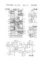
- FIG. 1is a perspective view of a blood gas analysis module in accordance with the invention
- FIG. 2is a perspective view showing the rear of the module shown in FIG. 1;
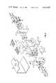
- FIG. 3is an exploded front view of components of the module of FIG. 1;
- FIG. 4is a perspective front view of a subassembly of the cell member and electrode sleeves
- FIG. 5Ais a side view of the cell member
- FIG. 5Bis a diagrammatic sectional view showing the sample flow path through the cell member
- FIG. 6is a sectional view showing the rotary spool valve 66 in a calibration position
- FIG. 7Ais an exploded rear view of the heater blocks 100, 102 and assembly plate 110;
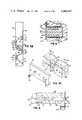
- FIG. 7Bis a circuit diagram of heater circuitry
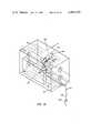
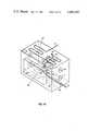
- FIG. 8is a sectional view through a heater block showing details of the sample preheater
- FIG. 9is an exploded front view of components of the module of FIG. 1 with cell member 30 and heater blocks 100, 102 assemble together;
- FIG. 10Ais a sectional view showing the sample flow path through the cell member
- FIG. 10Bis an enlarged sectional view of a portion of the sample flow path shown in FIG. 10A;
- FIG. 11is a diagrammatic view showing location of position sensors in the sample flow path in the module of FIG. 1;
- FIGS. 12 and 13are diagrammatic views similar to FIG. 11 showing two locations of a smaller sample (65 microliter volume) for analysis;
- FIG. 14is a diagram similar to FIG. 11 showing the flush flow path.
- FIG. 15is a diagram similar to FIG. 11 showing the flow path of calibration fluids in one of the calibration modes.
- FIG. 1A blood gas analysis module for use in a blood gas analysis system in accordance with the invention is shown in FIG. 1.
- That moduleincludes a housing 10 that has a front viewing window 12 and that receives a pO 2 electrode assembly 14 and a pH electrode assembly 16 at one end. As indicated in the rear perspective view of the module in FIG. 2, the housing receives a pCO 2 electrode assembly 18 and a reference electrode assembly 20 at the other end.
- the modulehas a sample inlet port 22 at one end surface below carbon dioxide assembly 18 and an outlet port 24 in its rear face.
- a valve shaft 26also projects from the rear face of the module.
- a window 28for admitting light to the flow-through sample cell 30 within module 10.
- a chamberOn either side of viewing window 12 is a chamber that is closed by a fill cap 32 and which contains water for humidifying calibration gases for calibration of each gas electrode. Ports 34, 35, 36, and 37 for connection to sources of calibration fluids are at the left end of the analysis module.
- Flow-through cell 30as fabricated from a clear colorless (acrylic) material and has four sleeves 40, 42, 44, 46 of the same material bonded to the cell body 30 to provide a leakproof unit.
- the rear surface 48 of cell body 30has a reflective coating that in combination with the light admitting top window 28 and the wide aperture of viewing window 12 enhances the visibility of the sample to be analyzed in the flow path 50 that extends through cell 30.
- the ports of sensor cavities 56 and 72open towards planar cell face 84 while ports 60 and 70 open towards opposed planar face 86.
- the diameter of each passage segmentis about 0.7 millimeter; the distance between cell surfaces 84 and 86 is about thirteen millimeters; and the volumetric displacement of the sample flow path between inlet port 52 and exit port 83 at the rear face of cell 30 is about 55 microliters.
- a suitable fluid controlis the rotary valve disclosed in copending application Ser. No. 104,296 filed Dec. 17, 1979, and entitled SPOOL VALVE and assigned to the same assignee as this application, the disclosure of which is incorporated herein by reference. As indicated in FIG.
- the spool 66 of the valvehas a through passage 68. Also formed in the spool 66 are for calibration passages 88, two of which are shown in the sectional view of FIG. 6. Each calibration passage 88 extends to a port 90 in the cylindrical surface of spool 66. Each port 90 is sealed by a captivated O-ring 92 and retainer plate 94 is secured with fastener 96.
- an aluminum heater block 100, 102each of which has a planar surface 104 that is clamped in heat transfer engagement with the corresponding planar surfaces 84, 86 of cell 30.
- a heater pad 106Secured to the front surface of each heater block is a heater pad 106 with a terminal connection 108.
- Common assembly plate 110as indicated in FIG. 7 is bolted to the rear of heater blocks 100, 102.
- a temperature control probe 112is mounted in recess 114 of block 102 between the electrode sleeve bores 116 and 118. Similar electrode sleeve bores 120 and 122 are formed in heater block 100. As indicated in FIG.
- sensing thermistor 112is connected in a bridge circuit 113 to which a regulated voltage is applied from voltage reference circuit 111.
- Balanced voltage amplifiers 115A, 115Bfeed current amplifier circuitry 117 to control power transistor 119 which in turn controls the flow of current through heater pads 106.
- a feedback loopis provided through resistor 121 and a reference is established by coarse adjustment 123 and fine adjustment 125.
- a temperature monitor 127is connected to the circuit by electronic switch 129. Heater pads 106 are wired in parallel to the proportional controller which regulates the temperature of the heater blocks 100 and 102, and thermal cutout 124 provides protection against overheating.
- a sample preheater 130Disposed in bore 126 of heater block 102 (see FIG. 8) is a sample preheater 130 which includes an aluminum sleeve 132, a stainless steel taper fitting 134, and a through stainless steel tube 136.
- a high electrical resistance epoxy coating on outer surface of aluminum sleeve 132isolates that sleeve from heater block 102.
- An elastomer seal 138is received in heater block 102 and in turn, the tapered end of fitting 134 is seatingly sealed in elastomer seal 138.
- Clamp plate 142engages an uncoated surface 144 of heater sleeve 132 and provides an electrical connection through fastener 146 to sensor lead 148 as a component of the electrical conductivity sample position sensing system.
- the front wall of the moduleincludes a clear plastic (acrylic) member 150 in which is formed viewing window 12, on either side of which is a humidifier chamber 152, 154 that is closed by cap 32.
- Calibration gas from inlet 37is flowed through conduit 156 into chamber 152 and out through conduit 158 which is disposed in bore 160 of heater block 100.
- a second calibration gas from inlet 36is flowed through conduit 162 to humdifier chamber 154 and out through conduit 164 which is disposed in bore 166 of heater block 102.
- the temperature of the humidifying water in each chamber 152, 154is maintained at essentially the stable system temperature (as determined by the temperature of heater blocks 100 and 102) as the acrylic member 150 is seated against the front surfaces of the heater blocks, and the gas flow rate through each chamber may be controlled by observation of bubbles through each water reservoir 152, 154.
- sleeves 40 and 42are inserted through bores 120 and 122 in heater block 100, and sleeves 44 and 46 are similarly inserted through bores 116 and 118 in heater block 102.
- the O 2 electrode assembly 14, together with retainer 170 and elastometer seal 172are inserted through sleeve 40 and seated at sensing cavity 56 of cell 30.
- CO 2 electrode assembly 18, pH electrode assembly 16 and reference electrode 20are similarly seated at cell cavities 60, 72, and 78 respectively.
- Each bulb-type projection 174 of an electrode assemblyis received in its sensing cavity with the seal 172 sealing the cavity.
- a compression type springaxially loads each electrode to maintain the seal.
- Each inlet capillary passage segmentslopes upwardly and extends to an inlet port 173 at the intersection between the cavity surface 176 and the planar cell face against which seal 172 is seated and each outlet capillary passage slopes upwardly away from an outlet port 175 at the top of the cavity.
- Each cavityis dimensioned so that the entire pH sensitive portion 177 of the bulb projection 174 is disposed within the sensing cavity and entirely exposed to the sample in the flow path with the periphery of the bulb-like projection 174 spaced about 1/2 millimeter from the cavity wall and the tip of the bulb-like projection spaced about 11/2 millimeters from the base of the cavity.
- Sample liquidflows upwardly through the flow path around and over the entire sensitive surface 177 of the sensing electrode in an analysis chamber of minimal volume, which together with the sloped capillary passage flow path reduces tendency to trap flush solution or sample within the cavity.
- the outlet port 175 at the top of each cavitymay be enlarged by a groove 178 to further relieve possible entrapment of gases.
- a cleaning solution preheater 192mounted on top of the heat blocks 100, 102 on electrical insulator sheet 190; and similar buffer solution preheaters 194, 196 are mounted on the bottom surfaces of blocks 100 and 102, respectively.
- a fiberglass insulated sleeve 198is disposed over the top, rear, and bottom walls of this subassembly and is encased in housing 10.
- the aluminum heat sink blocks 100, 102which are maintained at 37° C., stabilize the temperature of flow-through cell 30, gas conditioning chambers 152, 154, and preheaters 192, 194 and 196, in a module assembly that is about fifteen centimeters long, about eight centimeters high and about six centimeters deep.
- Blocks 100, 102are electrically grounded and provide shielding for electrodes 14, 16, 18, and 20.
- the sample flow path through the moduleis indicated in the diagram of FIG. 11.
- the sample to be analyzedis withdrawn from sampling vessel 200 by sampling needle 202 and flows through a first position sensor 204 to inlet 22 of sample preheater 120.
- the sampleemerges from tapered tip 134 of preheater 130 and flows through the serpentine path of measuring cell 30 from inlet port 52 serially past sensor port 56, sensor port 60, through valve 66, past sensor port 72 and reference port 78, through second position sensor 206 and third position sensor 208 and fourth position sensor 210 into the flush preheater 192 on top of the heater block and then out exit port 24 at the rear of the module.
- Position sensors 204, 206, 208, and 210function in a position sensing system that utilizes the electrical conductivity of the sample to complete electrical circuits, in conjunction with the sample preheater 130 and the rotary valve 66.
- a 210 hertz signalis applied to the sample preheater 130 and to the valve 66 for sample position sensing purposes.
- Flow control valve 66has three operative positions, an analysis position in which transverse passage 68 through the valve spool is aligned with passage segments 62 and 70; a first calibrating position (as shown in FIG. 6) in which calibration gas from inlet 37 is bubbled through humidifying chamber 152 and then flowed to valve passage 88a in the spool that is connected to passage segment 62 and a buffer liquid from inlet 35 is flowed through preheater 194 and the upper inlet 88b to passage segment 70; and a second calibrating position (with spool 66 rotated through a further 60 degree angle) in which a calibration gas from inlet 30 is flowed through bubble chamber 154 and port 88c of the spool valve for flow into passage segment 62 and a buffer from inlet 34 is flowed through preheater 196 to valve inlet 88d to passage segment 70.
- the sensing modulehas five operational modes: two calibration modes, two sample analysis modes, (a 65 microliter sample mode and a 120 microliter sample mode), and a flush mode.
- External microprocessor controlselects the appropriate fluid flow patterns for each function.
- rotary valve 66is indexed to the sample position as shown in FIG. 11.
- Sampling needle 202is inserted in sampling vessel 200 and the peristaltic pump connected to exit port 24 is operated to induct about 120 microliters of blood up to preheater 130.
- the conductivity of the blood samplecompletes a circuit between the preheater 130 and sampling needle 206, signaling the induction of the sample, and the pump is stopped to allow withdrawal of needle 202 from vessel 200.
- the pumpadvances the sample to valve 66, and the pump is stopped to allow equilibration of the oxygen electrode 14 and the carbon dioxide electrode 18.
- the pumpthen advances the 120 microliter sample to sensor 210.
- Crest 77provides electrolyte isolation between reference electrode 20 and pH electrode 16.
- the sample to be analyzedis inducted only to sensor 204 and then the sampling needle is withdrawn from the sampling vessel.
- the sampleis first advanced through preheater 130 to the sensor 206 (FIG. 12) where there is a pause for equilibration of the carbon dioxide and pH electrodes. At this time the data translating circuit for the oxygen electrode 14 is released and a pO 2 measurement on the microsample is made.
- the sampleis then advanced to sensor 208 (to the position shown in FIG. 13) and pH and carbon dioxide measurements are made. After the measurements have been completed, the sample is flushed from the module.
- the flush cycle flow pathis shown in FIG. 14.
- flow control valve 66remains in the sample position, and cleaning is accomplished by back flushing the system under pressure with flush solution being pumped through flush preheater 192 and the serpentine passage in cell 30 and through preheater 130 and the sampling needle 202 to waste along the path as indicated in FIG. 14.
- rotary valve 66is indexed (rotated 60 degrees) to a first calibration position and then indexed a further 60 degrees to a second calibration position.
- a calibration gas bubble chamberis connected to an inlet of valve 66 and the calibration gas is humidified by bubbling through the bubble chamber and then flows through the valve into passage segment 62 and past sensor ports 60 and 56 and out sample preheater.
- a buffer solutionis pumped by the aspiration pump connected to the exit port 24 through the selected buffer preheater and valve passage to passage segment 70 for flow past sensing port 72 and reference port 78.
Landscapes
- Health & Medical Sciences (AREA)
- Life Sciences & Earth Sciences (AREA)
- Engineering & Computer Science (AREA)
- Biomedical Technology (AREA)
- Chemical & Material Sciences (AREA)
- Hematology (AREA)
- Physics & Mathematics (AREA)
- Food Science & Technology (AREA)
- Molecular Biology (AREA)
- Urology & Nephrology (AREA)
- Ecology (AREA)
- Biophysics (AREA)
- Medicinal Chemistry (AREA)
- Analytical Chemistry (AREA)
- Biochemistry (AREA)
- General Health & Medical Sciences (AREA)
- General Physics & Mathematics (AREA)
- Immunology (AREA)
- Pathology (AREA)
- Optical Measuring Cells (AREA)
Abstract
Description
Claims (22)
Priority Applications (1)
| Application Number | Priority Date | Filing Date | Title |
|---|---|---|---|
| US06/391,102US4443407A (en) | 1981-04-02 | 1982-06-23 | Analysis system |
Applications Claiming Priority (2)
| Application Number | Priority Date | Filing Date | Title |
|---|---|---|---|
| US06/245,981US4361539A (en) | 1980-05-05 | 1981-04-02 | Analysis system |
| US06/391,102US4443407A (en) | 1981-04-02 | 1982-06-23 | Analysis system |
Related Parent Applications (1)
| Application Number | Title | Priority Date | Filing Date |
|---|---|---|---|
| US06/245,981DivisionUS4361539A (en) | 1980-05-05 | 1981-04-02 | Analysis system |
Publications (1)
| Publication Number | Publication Date |
|---|---|
| US4443407Atrue US4443407A (en) | 1984-04-17 |
Family
ID=26937622
Family Applications (1)
| Application Number | Title | Priority Date | Filing Date |
|---|---|---|---|
| US06/391,102Expired - Fee RelatedUS4443407A (en) | 1981-04-02 | 1982-06-23 | Analysis system |
Country Status (1)
| Country | Link |
|---|---|
| US (1) | US4443407A (en) |
Cited By (30)
| Publication number | Priority date | Publication date | Assignee | Title |
|---|---|---|---|---|
| US4596649A (en)* | 1984-03-16 | 1986-06-24 | Eppendorf Geratebau Netheler & Hinz Gmbh | Measuring system comprising ion-selective electrodes |
| US4627893A (en)* | 1984-03-28 | 1986-12-09 | Amdev, Inc. | Means and methods for quantitative determination of analyte in liquids |
| US4640821A (en)* | 1985-07-16 | 1987-02-03 | Fisher Scientific Company | Analysis apparatus |
| US4997627A (en)* | 1987-07-17 | 1991-03-05 | Fisher Scientific Company | Sample analysis |
| US5019238A (en)* | 1984-03-28 | 1991-05-28 | Baxter Diagnostics Inc. | Means for quantitative determination of analyte in liquids |
| US5057278A (en)* | 1990-04-26 | 1991-10-15 | Minnesota Mining And Manufacturing Company | Sterile loop calibration system |
| US5061631A (en)* | 1988-10-14 | 1991-10-29 | Fisher Scientific Company | Method, apparatus and solution for calibration of partial pressure value |
| US5094820A (en)* | 1990-04-26 | 1992-03-10 | Minnesota Mining And Manufacturing Company | Pump and calibration system |
| US5133937A (en)* | 1989-06-01 | 1992-07-28 | Iniziative Marittime, 1991 S.R.L. | Analysis system having a removable reaction cartridge and temperature control |
| US5156972A (en)* | 1989-09-05 | 1992-10-20 | The State Of Israel, Atomic Energy Commission, Soreq Nuclear Research Center | Analyte specific chemical sensor with a ligand and an analogue bound on the sensing surface |
| US5158868A (en)* | 1987-07-17 | 1992-10-27 | Iniziative Marittime 1991, S.R.L. | Method of sample analysis |
| US5171029A (en)* | 1990-04-26 | 1992-12-15 | Minnesota Mining And Manufacturing Company | Seal construction for pump apparatus |
| US5204266A (en)* | 1988-08-10 | 1993-04-20 | Instrumentation Laboratory Spa | Method and apparatus for liquid phase calibration of oxygen and carbon dioxide partial pressure |
| US5223224A (en)* | 1989-12-13 | 1993-06-29 | Gesellschaft Fur Biotechnologische Forschung Mbh (Gbf) | Sensor arrangement for flow injection analysis |
| US5278072A (en)* | 1990-04-26 | 1994-01-11 | Minnesota Mining And Manufacturing Company | Calibration system and housing |
| US5571396A (en)* | 1993-07-12 | 1996-11-05 | Dade International Inc. | Fluid analysis system and sensing electrode, electrode assembly, and sensing module components |
| WO1998021594A3 (en)* | 1996-11-12 | 1998-08-13 | Beckman Instruments Inc | Automatic chemistry analyzer with improved heated reaction cup assembly |
| US6123820A (en)* | 1998-06-05 | 2000-09-26 | Grupo Ch-Werfen, S.A. | Sensor cartridges |
| US6174289B1 (en)* | 1999-05-28 | 2001-01-16 | Orca Diagnostics Corporation | Cardiopulmonary exercise testing apparatus and method |
| US6289751B1 (en)* | 1997-07-21 | 2001-09-18 | Medica Corporation | Modular sensor system for a modular automated diagnostic apparatus |
| US20050002024A1 (en)* | 2003-05-28 | 2005-01-06 | Smiths Detection-Edgewood, Inc. | Device for polymerase chain reactions |
| US20100233751A1 (en)* | 2006-02-23 | 2010-09-16 | Medical Research Council | Apparatus and method for monitoring cultures |
| EP2339320A1 (en) | 2005-01-25 | 2011-06-29 | Oscillogy LLC | Temperature controller for small fluid samples having different heat capacities |
| ITMO20110063A1 (en)* | 2011-03-21 | 2012-09-22 | Rand Srl | DEVICE FOR THE MONITORING OF CHEMICAL-PHYSICAL PARAMETERS OF AN ORGANIC FLUID |
| US8596340B1 (en)* | 2010-10-13 | 2013-12-03 | Horn-Barber Technologies, LLC | Apparatus for heating liquid samples for analysis |
| US10391227B2 (en)* | 2014-05-15 | 2019-08-27 | Novalung Gmbh | Medico-technical measuring device and measuring method |
| US10463306B2 (en) | 2014-05-15 | 2019-11-05 | Novalung Gmbh | Medical measuring system and method for production of the measuring system |
| US10814054B2 (en) | 2015-10-23 | 2020-10-27 | Novalung Gmbh | Intermediate element for a medical extracorporeal fluid line, and system and method associated therewith |
| CN113819677A (en)* | 2021-10-22 | 2021-12-21 | 西安热工研究院有限公司 | A temperature control system suitable for online fluid monitoring |
| US20250016963A1 (en)* | 2022-03-08 | 2025-01-09 | Schneider Electric USA, Inc. | Electrically isolating thermal interface module for low voltage electrical devices |
Citations (22)
| Publication number | Priority date | Publication date | Assignee | Title |
|---|---|---|---|---|
| GB1084079A (en)* | 1964-11-30 | Beckman Instruments Inc | ||
| GB1047138A (en)* | 1963-04-15 | 1966-11-02 | Beckman Instruments Inc | Fluid sample examining apparatus |
| GB1068661A (en)* | 1962-10-13 | 1967-05-10 | Lucia Eschweiler | Electrical gas analysis equipment |
| US3522725A (en)* | 1969-01-08 | 1970-08-04 | Waters Associates Inc | Liquid chromatograph |
| US3640267A (en)* | 1969-12-15 | 1972-02-08 | Damon Corp | Clinical sample container |
| US3648159A (en)* | 1970-03-11 | 1972-03-07 | Us Air Force | Portable, self-contained system for analyzing biological fluids or the like |
| US3672843A (en)* | 1970-04-07 | 1972-06-27 | Instrumentation Labor Inc | Fluid analyzing apparatus |
| US3763422A (en)* | 1971-10-21 | 1973-10-02 | Corning Glass Works | Method and apparatus for electrochemical analysis of small samples of blood |
| GB1346533A (en)* | 1971-03-18 | 1974-02-13 | ||
| US3811841A (en)* | 1972-08-09 | 1974-05-21 | Technicon Instr | Gating flow cell structure for continuous-flow analysis systems |
| US3811842A (en)* | 1972-06-07 | 1974-05-21 | Technicon Instr | Temperature-controlled fluid manifold for a fluid manifold for a fluid system of an automated sample analyzer |
| US3884640A (en)* | 1972-10-26 | 1975-05-20 | Gen Electric | Apparatus to analyze fluids |
| US3960498A (en)* | 1974-08-01 | 1976-06-01 | Instrumentation Laboratory, Inc. | Electrochemical analysis system |
| US3963440A (en)* | 1974-06-27 | 1976-06-15 | Instrumentation Laboratory, Inc. | Analysis system |
| US4086061A (en)* | 1977-02-28 | 1978-04-25 | Beckman Instruments, Inc. | Temperature control system for chemical reaction cell |
| GB1535361A (en)* | 1976-03-17 | 1978-12-13 | Owens Illinois Inc | Electrochemical cell |
| DE2848073A1 (en)* | 1977-11-16 | 1979-05-17 | Avl Ag | PROCEDURE AND EQUIPMENT FOR MONITORING AND CONTROLLING THE FILLING PROCESS OF A LONGITUDINAL MEASURING CHAMBER |
| US4160714A (en)* | 1975-10-15 | 1979-07-10 | Radiometer A/S | Measuring chamber unit |
| US4202747A (en)* | 1978-07-06 | 1980-05-13 | Beckman Instruments, Inc. | Flow cell fluid and sample supply mechanism |
| US4207394A (en)* | 1976-01-28 | 1980-06-10 | Mcdonnell Douglas Corporation | Process and apparatus for analyzing specimens for the presence of microorganisms therein |
| US4221567A (en)* | 1977-12-23 | 1980-09-09 | Intermountain Health Care | Sampling and determination of diffusible chemical substances |
| US4361540A (en)* | 1980-05-05 | 1982-11-30 | Instrumentation Laboratory Inc. | Analysis system |
- 1982
- 1982-06-23USUS06/391,102patent/US4443407A/ennot_activeExpired - Fee Related
Patent Citations (22)
| Publication number | Priority date | Publication date | Assignee | Title |
|---|---|---|---|---|
| GB1068661A (en)* | 1962-10-13 | 1967-05-10 | Lucia Eschweiler | Electrical gas analysis equipment |
| GB1047138A (en)* | 1963-04-15 | 1966-11-02 | Beckman Instruments Inc | Fluid sample examining apparatus |
| GB1084079A (en)* | 1964-11-30 | Beckman Instruments Inc | ||
| US3522725A (en)* | 1969-01-08 | 1970-08-04 | Waters Associates Inc | Liquid chromatograph |
| US3640267A (en)* | 1969-12-15 | 1972-02-08 | Damon Corp | Clinical sample container |
| US3648159A (en)* | 1970-03-11 | 1972-03-07 | Us Air Force | Portable, self-contained system for analyzing biological fluids or the like |
| US3672843A (en)* | 1970-04-07 | 1972-06-27 | Instrumentation Labor Inc | Fluid analyzing apparatus |
| GB1346533A (en)* | 1971-03-18 | 1974-02-13 | ||
| US3763422A (en)* | 1971-10-21 | 1973-10-02 | Corning Glass Works | Method and apparatus for electrochemical analysis of small samples of blood |
| US3811842A (en)* | 1972-06-07 | 1974-05-21 | Technicon Instr | Temperature-controlled fluid manifold for a fluid manifold for a fluid system of an automated sample analyzer |
| US3811841A (en)* | 1972-08-09 | 1974-05-21 | Technicon Instr | Gating flow cell structure for continuous-flow analysis systems |
| US3884640A (en)* | 1972-10-26 | 1975-05-20 | Gen Electric | Apparatus to analyze fluids |
| US3963440A (en)* | 1974-06-27 | 1976-06-15 | Instrumentation Laboratory, Inc. | Analysis system |
| US3960498A (en)* | 1974-08-01 | 1976-06-01 | Instrumentation Laboratory, Inc. | Electrochemical analysis system |
| US4160714A (en)* | 1975-10-15 | 1979-07-10 | Radiometer A/S | Measuring chamber unit |
| US4207394A (en)* | 1976-01-28 | 1980-06-10 | Mcdonnell Douglas Corporation | Process and apparatus for analyzing specimens for the presence of microorganisms therein |
| GB1535361A (en)* | 1976-03-17 | 1978-12-13 | Owens Illinois Inc | Electrochemical cell |
| US4086061A (en)* | 1977-02-28 | 1978-04-25 | Beckman Instruments, Inc. | Temperature control system for chemical reaction cell |
| DE2848073A1 (en)* | 1977-11-16 | 1979-05-17 | Avl Ag | PROCEDURE AND EQUIPMENT FOR MONITORING AND CONTROLLING THE FILLING PROCESS OF A LONGITUDINAL MEASURING CHAMBER |
| US4221567A (en)* | 1977-12-23 | 1980-09-09 | Intermountain Health Care | Sampling and determination of diffusible chemical substances |
| US4202747A (en)* | 1978-07-06 | 1980-05-13 | Beckman Instruments, Inc. | Flow cell fluid and sample supply mechanism |
| US4361540A (en)* | 1980-05-05 | 1982-11-30 | Instrumentation Laboratory Inc. | Analysis system |
Cited By (42)
| Publication number | Priority date | Publication date | Assignee | Title |
|---|---|---|---|---|
| US4596649A (en)* | 1984-03-16 | 1986-06-24 | Eppendorf Geratebau Netheler & Hinz Gmbh | Measuring system comprising ion-selective electrodes |
| US4627893A (en)* | 1984-03-28 | 1986-12-09 | Amdev, Inc. | Means and methods for quantitative determination of analyte in liquids |
| US5019238A (en)* | 1984-03-28 | 1991-05-28 | Baxter Diagnostics Inc. | Means for quantitative determination of analyte in liquids |
| US4640821A (en)* | 1985-07-16 | 1987-02-03 | Fisher Scientific Company | Analysis apparatus |
| US4997627A (en)* | 1987-07-17 | 1991-03-05 | Fisher Scientific Company | Sample analysis |
| US5158868A (en)* | 1987-07-17 | 1992-10-27 | Iniziative Marittime 1991, S.R.L. | Method of sample analysis |
| US5204266A (en)* | 1988-08-10 | 1993-04-20 | Instrumentation Laboratory Spa | Method and apparatus for liquid phase calibration of oxygen and carbon dioxide partial pressure |
| US5061631A (en)* | 1988-10-14 | 1991-10-29 | Fisher Scientific Company | Method, apparatus and solution for calibration of partial pressure value |
| US5133937A (en)* | 1989-06-01 | 1992-07-28 | Iniziative Marittime, 1991 S.R.L. | Analysis system having a removable reaction cartridge and temperature control |
| US5156972A (en)* | 1989-09-05 | 1992-10-20 | The State Of Israel, Atomic Energy Commission, Soreq Nuclear Research Center | Analyte specific chemical sensor with a ligand and an analogue bound on the sensing surface |
| US5223224A (en)* | 1989-12-13 | 1993-06-29 | Gesellschaft Fur Biotechnologische Forschung Mbh (Gbf) | Sensor arrangement for flow injection analysis |
| US5057278A (en)* | 1990-04-26 | 1991-10-15 | Minnesota Mining And Manufacturing Company | Sterile loop calibration system |
| US5171029A (en)* | 1990-04-26 | 1992-12-15 | Minnesota Mining And Manufacturing Company | Seal construction for pump apparatus |
| US5094820A (en)* | 1990-04-26 | 1992-03-10 | Minnesota Mining And Manufacturing Company | Pump and calibration system |
| US5278072A (en)* | 1990-04-26 | 1994-01-11 | Minnesota Mining And Manufacturing Company | Calibration system and housing |
| US5348706A (en)* | 1990-04-26 | 1994-09-20 | Minnesota Mining And Manufacturing Company | Calibration system and method for making |
| US5420038A (en)* | 1990-04-26 | 1995-05-30 | Minnesota Mining And Manufacturing Company | Calibration system and housing |
| US5571396A (en)* | 1993-07-12 | 1996-11-05 | Dade International Inc. | Fluid analysis system and sensing electrode, electrode assembly, and sensing module components |
| WO1998021594A3 (en)* | 1996-11-12 | 1998-08-13 | Beckman Instruments Inc | Automatic chemistry analyzer with improved heated reaction cup assembly |
| US5863506A (en)* | 1996-11-12 | 1999-01-26 | Beckman Instruments, Inc. | Automatic chemistry analyzer with improved heated reaction cup assembly |
| AU736838C (en)* | 1996-11-12 | 2002-03-28 | Beckman Coulter, Inc. | Automatic chemistry analyzer with improved heated reaction cup assembly |
| AU736838B2 (en)* | 1996-11-12 | 2001-08-02 | Beckman Coulter, Inc. | Automatic chemistry analyzer with improved heated reaction cup assembly |
| US6289751B1 (en)* | 1997-07-21 | 2001-09-18 | Medica Corporation | Modular sensor system for a modular automated diagnostic apparatus |
| US6123820A (en)* | 1998-06-05 | 2000-09-26 | Grupo Ch-Werfen, S.A. | Sensor cartridges |
| US6174289B1 (en)* | 1999-05-28 | 2001-01-16 | Orca Diagnostics Corporation | Cardiopulmonary exercise testing apparatus and method |
| US20050002024A1 (en)* | 2003-05-28 | 2005-01-06 | Smiths Detection-Edgewood, Inc. | Device for polymerase chain reactions |
| US7170594B2 (en)* | 2003-05-28 | 2007-01-30 | Smiths Detection, Inc. | Device for polymerase chain reactions |
| EP2339320A1 (en) | 2005-01-25 | 2011-06-29 | Oscillogy LLC | Temperature controller for small fluid samples having different heat capacities |
| US8507262B2 (en)* | 2006-02-23 | 2013-08-13 | Cytoprom Ltd | Apparatus and method for monitoring cultures |
| US20100233751A1 (en)* | 2006-02-23 | 2010-09-16 | Medical Research Council | Apparatus and method for monitoring cultures |
| US8596340B1 (en)* | 2010-10-13 | 2013-12-03 | Horn-Barber Technologies, LLC | Apparatus for heating liquid samples for analysis |
| US9329108B1 (en) | 2010-10-13 | 2016-05-03 | Horn Jr Jack Delaney | Apparatus for handling liquid samples for analysis having a rinse system |
| US9335239B1 (en) | 2010-10-13 | 2016-05-10 | Horn-Barber Technologies, LLC | Feed system for delivering liquids to an analytical system |
| US10605703B1 (en) | 2010-10-13 | 2020-03-31 | Jack Delaney Horn, Jr. | Pressurized gas supply system |
| WO2012127422A1 (en)* | 2011-03-21 | 2012-09-27 | Rand S.R.L. | Device for the extracorporeal monitoring of blood |
| ITMO20110063A1 (en)* | 2011-03-21 | 2012-09-22 | Rand Srl | DEVICE FOR THE MONITORING OF CHEMICAL-PHYSICAL PARAMETERS OF AN ORGANIC FLUID |
| US10391227B2 (en)* | 2014-05-15 | 2019-08-27 | Novalung Gmbh | Medico-technical measuring device and measuring method |
| US10463306B2 (en) | 2014-05-15 | 2019-11-05 | Novalung Gmbh | Medical measuring system and method for production of the measuring system |
| US11357899B2 (en) | 2014-05-15 | 2022-06-14 | Novalung Gmbh | Measuring device and method for measuring a property of a fluid in a line |
| US10814054B2 (en) | 2015-10-23 | 2020-10-27 | Novalung Gmbh | Intermediate element for a medical extracorporeal fluid line, and system and method associated therewith |
| CN113819677A (en)* | 2021-10-22 | 2021-12-21 | 西安热工研究院有限公司 | A temperature control system suitable for online fluid monitoring |
| US20250016963A1 (en)* | 2022-03-08 | 2025-01-09 | Schneider Electric USA, Inc. | Electrically isolating thermal interface module for low voltage electrical devices |
Similar Documents
| Publication | Publication Date | Title |
|---|---|---|
| US4443407A (en) | Analysis system | |
| US4361539A (en) | Analysis system | |
| US4361540A (en) | Analysis system | |
| CA1046795A (en) | Fluid sample analysis system | |
| US3884640A (en) | Apparatus to analyze fluids | |
| US4841974A (en) | Apparatus and method for the examination of a liquid medium | |
| US3664178A (en) | Fluid handling apparatus | |
| EP0213343B1 (en) | Blood analyzer | |
| US4818361A (en) | Combined pH and dissolved carbon dioxide gas sensor | |
| US7242474B2 (en) | Cytometer having fluid core stream position control | |
| US4654127A (en) | Self-calibrating single-use sensing device for clinical chemistry and method of use | |
| US8366316B2 (en) | Sensor apparatus systems, devices and methods | |
| CA1091560A (en) | Temperature control system for chemical reaction cell | |
| CA1142227A (en) | Temperature compensation for disposable electrochemical sensors | |
| US4197853A (en) | PO2 /PCO2 sensor | |
| US4003705A (en) | Analysis apparatus and method of measuring rate of change of electrolyte pH | |
| US20080240929A1 (en) | Pumping Cassette | |
| US3648159A (en) | Portable, self-contained system for analyzing biological fluids or the like | |
| JPH0476427B2 (en) | ||
| EP1598664A1 (en) | Fluid conductivity measuring cell | |
| EP0179129A4 (en) | Self-calibrating single-use sensing device for clinical chemistry analyzer. | |
| EP4177698B1 (en) | Sensor system for fluids | |
| US5571396A (en) | Fluid analysis system and sensing electrode, electrode assembly, and sensing module components | |
| CN102177432B (en) | Sensor system | |
| US6523426B1 (en) | Water quality measuring apparatus with a sensing wafer clamped between two o-rings |
Legal Events
| Date | Code | Title | Description |
|---|---|---|---|
| AS | Assignment | Owner name:ALLIED CORPORATION COLUMBIA ROAD AND PARK AVE., MO Free format text:ASSIGNMENT OF ASSIGNORS INTEREST.;ASSIGNOR:INSTRUMENTATION LABORATORY INC., A DE CORP;REEL/FRAME:004211/0801 Effective date:19840103 | |
| FEPP | Fee payment procedure | Free format text:PAYOR NUMBER ASSIGNED (ORIGINAL EVENT CODE: ASPN); ENTITY STATUS OF PATENT OWNER: LARGE ENTITY | |
| AS | Assignment | Owner name:FISHER SCIENTIFIC COMPANY A CORP OF DE Free format text:ASSIGNMENT OF ASSIGNORS INTEREST.;ASSIGNOR:ALLIED CORPORATION A NY CORP;REEL/FRAME:004634/0501 Effective date:19860815 | |
| FPAY | Fee payment | Year of fee payment:4 | |
| FEPP | Fee payment procedure | Free format text:PAYER NUMBER DE-ASSIGNED (ORIGINAL EVENT CODE: RMPN); ENTITY STATUS OF PATENT OWNER: LARGE ENTITY | |
| FEPP | Fee payment procedure | Free format text:PAYOR NUMBER ASSIGNED (ORIGINAL EVENT CODE: ASPN); ENTITY STATUS OF PATENT OWNER: LARGE ENTITY | |
| FEPP | Fee payment procedure | Free format text:PAYMENT IS IN EXCESS OF AMOUNT REQUIRED. REFUND SCHEDULED (ORIGINAL EVENT CODE: F169); ENTITY STATUS OF PATENT OWNER: LARGE ENTITY | |
| REFU | Refund | Free format text:REFUND - PAYMENT OF MAINTENANCE FEE, 8TH YEAR, PL 96-517 (ORIGINAL EVENT CODE: R171); ENTITY STATUS OF PATENT OWNER: LARGE ENTITY | |
| AS | Assignment | Owner name:INIZIATIVE MARITTIME 1991, S.R.L., A CORPORATION Free format text:ASSIGNMENT OF ASSIGNORS INTEREST.;ASSIGNOR:FISHER SCIENTIFIC COMPANY, A CORP. OF DE;REEL/FRAME:005891/0407 Effective date:19911023 | |
| AS | Assignment | Owner name:CITIBANK N.A. Free format text:SECURITY INTEREST;ASSIGNOR:INIZIATIVE MARITTIME 1991, S.R.L.;REEL/FRAME:005913/0325 Effective date:19911023 | |
| AS | Assignment | Owner name:IL HOLDING S.P.A. Free format text:CHANGE OF NAME;ASSIGNOR:INIZIATIVE MARITTIME 1991 S.R.L.;REEL/FRAME:006179/0983 Effective date:19920219 | |
| REMI | Maintenance fee reminder mailed | ||
| LAPS | Lapse for failure to pay maintenance fees | ||
| FP | Lapsed due to failure to pay maintenance fee | Effective date:19960417 | |
| STCH | Information on status: patent discontinuation | Free format text:PATENT EXPIRED DUE TO NONPAYMENT OF MAINTENANCE FEES UNDER 37 CFR 1.362 |