US4443233A - Mist separator - Google Patents
Mist separatorDownload PDFInfo
- Publication number
- US4443233A US4443233AUS06/412,328US41232882AUS4443233AUS 4443233 AUS4443233 AUS 4443233AUS 41232882 AUS41232882 AUS 41232882AUS 4443233 AUS4443233 AUS 4443233A
- Authority
- US
- United States
- Prior art keywords
- perforated screen
- separator
- fiber bed
- perforations
- screen separator
- Prior art date
- Legal status (The legal status is an assumption and is not a legal conclusion. Google has not performed a legal analysis and makes no representation as to the accuracy of the status listed.)
- Expired - Lifetime
Links
- 239000003595mistSubstances0.000titleclaimsabstractdescription77
- 239000000835fiberSubstances0.000claimsabstractdescription121
- 238000000034methodMethods0.000claimsabstractdescription7
- 230000008569processEffects0.000claimsabstractdescription7
- 239000002245particleSubstances0.000claimsdescription48
- 238000011144upstream manufacturingMethods0.000claimsdescription25
- 239000011800void materialSubstances0.000claimsdescription5
- 239000000463materialSubstances0.000abstractdescription5
- 239000007789gasSubstances0.000description63
- 239000000443aerosolSubstances0.000description37
- 238000011068loading methodMethods0.000description14
- 238000012360testing methodMethods0.000description12
- 229910052751metalInorganic materials0.000description10
- 239000002184metalSubstances0.000description10
- 239000007788liquidSubstances0.000description6
- 239000007787solidSubstances0.000description4
- 238000010276constructionMethods0.000description3
- 238000013461designMethods0.000description3
- 238000012856packingMethods0.000description3
- 230000008859changeEffects0.000description2
- 239000003365glass fiberSubstances0.000description2
- 238000004519manufacturing processMethods0.000description2
- 239000007921spraySubstances0.000description2
- 238000013459approachMethods0.000description1
- 230000008901benefitEffects0.000description1
- 239000000919ceramicSubstances0.000description1
- 238000011143downstream manufacturingMethods0.000description1
- 239000011521glassSubstances0.000description1
- 230000005484gravityEffects0.000description1
- 238000009434installationMethods0.000description1
- 238000005259measurementMethods0.000description1
- QSHDDOUJBYECFT-UHFFFAOYSA-NmercuryChemical compound[Hg]QSHDDOUJBYECFT-UHFFFAOYSA-N0.000description1
- 229910052753mercuryInorganic materials0.000description1
- 239000000203mixtureSubstances0.000description1
- 238000012986modificationMethods0.000description1
- 230000004048modificationEffects0.000description1
- 235000020030perryNutrition0.000description1
- 239000004033plasticSubstances0.000description1
- 230000009467reductionEffects0.000description1
- 238000000926separation methodMethods0.000description1
- 238000004513sizingMethods0.000description1
- 239000000126substanceSubstances0.000description1
- XLYOFNOQVPJJNP-UHFFFAOYSA-NwaterSubstancesOXLYOFNOQVPJJNP-UHFFFAOYSA-N0.000description1
- 238000004804windingMethods0.000description1
Images


Classifications
- B—PERFORMING OPERATIONS; TRANSPORTING
- B01—PHYSICAL OR CHEMICAL PROCESSES OR APPARATUS IN GENERAL
- B01D—SEPARATION
- B01D45/00—Separating dispersed particles from gases or vapours by gravity, inertia, or centrifugal forces
- B01D45/04—Separating dispersed particles from gases or vapours by gravity, inertia, or centrifugal forces by utilising inertia
- B01D45/08—Separating dispersed particles from gases or vapours by gravity, inertia, or centrifugal forces by utilising inertia by impingement against baffle separators
Definitions
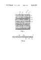
- FIG. 1is a front view of an example of the perforated screen of this invention.
- the operation of the bicomponent impaction separator 36 shown in FIG. 5is fully described above.
- the bicomponent impaction separator 28 of FIG. 3, which has a perforated screen separator 29 on the upstream face of the fiber bed mist eliminator 30,operates in a substantially similar manner.
- the upstream perforated screen separator 29is used to collect essentially all particles greater than 10 microns and the fiber bed mist eliminator 30 collects substantially all submicron size and larger particulates from the gas stream. As the aerosols are collected within the fiber bed mist eliminator 30, and as they drain from the bed, they will agglomerate to thus form larger particles and droplets of collected mist.
Landscapes
- Chemical & Material Sciences (AREA)
- Chemical Kinetics & Catalysis (AREA)
- Filtering Of Dispersed Particles In Gases (AREA)
Abstract
Description
TABLE 1 __________________________________________________________________________ PERFORATED ELEMENT SCREEN BED TOTAL DRIP PAN ELEMENT OVERALL >3 MICRON DATA SEPARATOR VELOCITY LOADING LOADING LOADING ΔP RE-ENTRAINMENT POINT USED (MPS) (G/M.sup.3) (G/M.sup.3) (G/M.sup.3) (MMHg) (G/M.sup.3) __________________________________________________________________________1 NO 1.46 18.1 2.7 15.4 7.19 0.40 2 NO 1.48 18.9 2.7 16.2 7.25 0.33 MEAN 1.47 18.5 2.7 15.8 7.22 0.36 3 YES 1.49 14.2 11.0 3.2 5.96 .004 4 YES 1.47 21.8 18.3 3.5 5.96 .006 MEAN 1.48 18.0 14.6 3.4 5.96 .005 __________________________________________________________________________
TABLE 2 __________________________________________________________________________ LARGE PARTICLE REMAINING SMALL TOTAL LOADING REMOVED PARTICLE LOADING GAS INLET BY PERFORATED REMOVED BY FIBER MIST REMOVAL BY VELOCITY LOADING SCREEN SEPARATOR BED PERFORATED SCREEN (MPS) (G/M.sup.3) (G/M.sup.3) (G/M.sup.3) SEPARATOR (%) __________________________________________________________________________2.6 17.3 16.85 0.45 97.4 2.2 8.5 8.26 0.24 97.1 __________________________________________________________________________
TABLE 3 __________________________________________________________________________TARGET TARGET TYPE ALIGNMENT NUMBER OF 10 MICRON WIDTH SPACING OF ERROR TARGETS COLLECTION (CENTIMETERS) (CENTIMETERS) TARGET (CENTIMETERS) REQUIRED EFFICIENCY __________________________________________________________________________ (%) 0.32 -- Perf. Screen 0 1 83.3 0.32 any ≧ 1.27 Perf. Screen 0 2 97.2 0.32 any ≧ 1.27 Perf. Screen 0 3 99.5 0.32 0.32 Baffles 0 2 69.9 0.32 0.32 Baffles 0.08 3 77.3 0.64 0.64 Baffles 0 4 75.7 0.64 0.64 Baffles 0.08 5 79.7 0.95 0.95 Baffles 0 8 72.9 0.95 0.95 Baffles 0.08 10 78.2 1.27 1.27 Baffles 0 25 77.3 __________________________________________________________________________
Claims (9)
Priority Applications (5)
| Application Number | Priority Date | Filing Date | Title |
|---|---|---|---|
| US06/412,328US4443233A (en) | 1982-08-27 | 1982-08-27 | Mist separator |
| MA20099AMA19877A1 (en) | 1982-08-27 | 1983-08-16 | FOG SEPARATOR. |
| EP83870087AEP0102344B1 (en) | 1982-08-27 | 1983-08-25 | Mist separator |
| ZA836355AZA836355B (en) | 1982-08-27 | 1983-08-26 | Mist separator |
| CA000435462ACA1191459A (en) | 1982-08-27 | 1983-08-26 | Mist separator |
Applications Claiming Priority (1)
| Application Number | Priority Date | Filing Date | Title |
|---|---|---|---|
| US06/412,328US4443233A (en) | 1982-08-27 | 1982-08-27 | Mist separator |
Publications (1)
| Publication Number | Publication Date |
|---|---|
| US4443233Atrue US4443233A (en) | 1984-04-17 |
Family
ID=23632556
Family Applications (1)
| Application Number | Title | Priority Date | Filing Date |
|---|---|---|---|
| US06/412,328Expired - LifetimeUS4443233A (en) | 1982-08-27 | 1982-08-27 | Mist separator |
Country Status (5)
| Country | Link |
|---|---|
| US (1) | US4443233A (en) |
| EP (1) | EP0102344B1 (en) |
| CA (1) | CA1191459A (en) |
| MA (1) | MA19877A1 (en) |
| ZA (1) | ZA836355B (en) |
Cited By (37)
| Publication number | Priority date | Publication date | Assignee | Title |
|---|---|---|---|---|
| US4915714A (en)* | 1988-06-23 | 1990-04-10 | Teague Richard K | Fiber bed element and process for removing small particles of liquids and solids from a gas stream |
| US5223119A (en)* | 1992-02-28 | 1993-06-29 | David Davies | Gas treatment method for removal of liquid droplets |
| US5384044A (en)* | 1993-09-07 | 1995-01-24 | Techniweave, Inc. | Fluid separation devices and methods of making same |
| US5598890A (en)* | 1995-10-23 | 1997-02-04 | Baker Hughes Inc. | Completion assembly |
| US5611399A (en)* | 1995-11-13 | 1997-03-18 | Baker Hughes Incorporated | Screen and method of manufacturing |
| US5624560A (en)* | 1995-04-07 | 1997-04-29 | Baker Hughes Incorporated | Wire mesh filter including a protective jacket |
| US5642781A (en)* | 1994-10-07 | 1997-07-01 | Baker Hughes Incorporated | Multi-passage sand control screen |
| US5653786A (en)* | 1994-03-30 | 1997-08-05 | Peerless Manufacturing Company | High capacity marine separator |
| US5711880A (en)* | 1995-09-02 | 1998-01-27 | Braun Aktiengesellschaft | Filtering means for the filtration of extraction beverages, in particular espresso |
| US6071419A (en)* | 1993-10-20 | 2000-06-06 | Products Unlimited, Inc. | Fluid filter, method of making and using thereof |
| US6251168B1 (en)* | 1999-07-23 | 2001-06-26 | Hudson Products Corporation | High efficiency gas scrubber using combined coalescing media and centrifugal cyclone |
| US6419721B1 (en)* | 1998-04-03 | 2002-07-16 | Psi Global Ltd. | Coalescing filters |
| US20030061611A1 (en)* | 2001-09-26 | 2003-03-27 | Ramesh Pendakur | Notifying users of available content and content reception based on user profiles |
| US6770121B1 (en) | 2002-09-12 | 2004-08-03 | Harbison-Fischer, Inc. | Separator with regions of differing surface tensions |
| US6923911B1 (en) | 1993-10-20 | 2005-08-02 | Scott B. Beier | Method of filtering air through an air passageway |
| US20060096932A1 (en)* | 2004-11-05 | 2006-05-11 | Dema Keh B | High strength, high capacity filter media and structure |
| US20060150594A1 (en)* | 2005-01-07 | 2006-07-13 | Monsanto Enviro-Chem Systems, Inc. | Fiber collecting media strip for a mist eliminator |
| US20070175191A1 (en)* | 2006-01-27 | 2007-08-02 | Mecs, Inc. | Fiber Bed assembly and fiber bed therefor |
| US7291196B1 (en)* | 2006-11-16 | 2007-11-06 | Lerner Bernard J | Filamentary pad for improved mist elimination and mass transfer |
| US20070277485A1 (en)* | 2006-05-31 | 2007-12-06 | Gas Liquids Engineering Ltd. | Apparatus and method for enhanced droplet collection in gas flows |
| US20080283476A1 (en)* | 2007-05-14 | 2008-11-20 | Global Finishing L.L.C. | Fluid filter and filtering method |
| USD583399S1 (en)* | 2007-04-12 | 2008-12-23 | Smc Corporation | Mist separator |
| US20090044702A1 (en)* | 2007-02-22 | 2009-02-19 | Adamek Daniel E | Filter element and method |
| US20110023428A1 (en)* | 2008-10-29 | 2011-02-03 | Mecs, Inc. | Compact fiber bed mist eliminator |
| US20110154790A1 (en)* | 2005-02-22 | 2011-06-30 | Donaldson Company, Inc. | Aerosol separator |
| US8057567B2 (en) | 2004-11-05 | 2011-11-15 | Donaldson Company, Inc. | Filter medium and breather filter structure |
| US8177875B2 (en) | 2005-02-04 | 2012-05-15 | Donaldson Company, Inc. | Aerosol separator; and method |
| US8267681B2 (en) | 2009-01-28 | 2012-09-18 | Donaldson Company, Inc. | Method and apparatus for forming a fibrous media |
| US20130047562A1 (en)* | 2011-08-30 | 2013-02-28 | Daniel Paris | Liquid knockout drum |
| US8642482B2 (en) | 2008-07-04 | 2014-02-04 | Tokyo Electron Limited | Plasma etching method, control program and computer storage medium |
| US20140318277A1 (en)* | 2013-04-26 | 2014-10-30 | Atlas Technology Corp. | Sampling device adapted for sampling airborne components |
| US9005340B2 (en) | 2012-10-04 | 2015-04-14 | Mecs, Inc. | Fiber bed assembly including a re-entrainment control device for a fiber bed mist eliminator |
| US9114339B2 (en) | 2007-02-23 | 2015-08-25 | Donaldson Company, Inc. | Formed filter element |
| US20160108816A1 (en)* | 2014-10-17 | 2016-04-21 | General Electric Company | Media Pads with Mist Elimination Features |
| US20190075985A1 (en)* | 2017-09-14 | 2019-03-14 | Skitter & Squirt Adventures, Llc | System and method for vacuum-powered debris separation |
| USRE47737E1 (en) | 2004-11-05 | 2019-11-26 | Donaldson Company, Inc. | Filter medium and structure |
| US12172111B2 (en) | 2004-11-05 | 2024-12-24 | Donaldson Company, Inc. | Filter medium and breather filter structure |
Citations (9)
| Publication number | Priority date | Publication date | Assignee | Title |
|---|---|---|---|---|
| US2389435A (en)* | 1942-07-09 | 1945-11-20 | Electrolux Corp | Filter material |
| GB778040A (en)* | 1954-12-20 | 1957-07-03 | Westinghouse Electric Int Co | Improvements in or relating to explosion-proof enclosures |
| GB861844A (en)* | 1958-07-05 | 1961-03-01 | Knecht Filterwerke Gmbh | A filter pack, particularly for use as an air cleaner in internal combustion engines |
| US3679062A (en)* | 1969-12-17 | 1972-07-25 | Ambac Ind | Filter leaf and method of making the same |
| US4086070A (en)* | 1975-12-22 | 1978-04-25 | Monsanto Company | Fiber bed separator and method for separation of aerosols from gases without re-entrainment |
| US4233042A (en)* | 1978-03-06 | 1980-11-11 | Incom International Inc. | Air-oil separator |
| US4249918A (en)* | 1979-05-21 | 1981-02-10 | Monsanto Company | Fiber bed element and process for removing aerosols from gases |
| US4300918A (en)* | 1978-05-08 | 1981-11-17 | Parmatic Filter Corporation | Method for removing moisture particles |
| US4319898A (en)* | 1981-03-20 | 1982-03-16 | Air Filter Corporation | Louver grease filter |
Family Cites Families (3)
| Publication number | Priority date | Publication date | Assignee | Title |
|---|---|---|---|---|
| AT160104B (en)* | 1938-05-14 | 1941-02-10 | Heinrich Schloz | Air filter. |
| DE1654741U (en)* | 1953-02-21 | 1953-04-30 | Schloz Motor Condensator | FILTER CAPSULE FOR OIL-WET AIR FILTER. |
| FR1466489A (en)* | 1965-12-07 | 1967-01-20 | Filter cartridge for air filter |
- 1982
- 1982-08-27USUS06/412,328patent/US4443233A/ennot_activeExpired - Lifetime
- 1983
- 1983-08-16MAMA20099Apatent/MA19877A1/enunknown
- 1983-08-25EPEP83870087Apatent/EP0102344B1/ennot_activeExpired
- 1983-08-26CACA000435462Apatent/CA1191459A/ennot_activeExpired
- 1983-08-26ZAZA836355Apatent/ZA836355B/enunknown
Patent Citations (9)
| Publication number | Priority date | Publication date | Assignee | Title |
|---|---|---|---|---|
| US2389435A (en)* | 1942-07-09 | 1945-11-20 | Electrolux Corp | Filter material |
| GB778040A (en)* | 1954-12-20 | 1957-07-03 | Westinghouse Electric Int Co | Improvements in or relating to explosion-proof enclosures |
| GB861844A (en)* | 1958-07-05 | 1961-03-01 | Knecht Filterwerke Gmbh | A filter pack, particularly for use as an air cleaner in internal combustion engines |
| US3679062A (en)* | 1969-12-17 | 1972-07-25 | Ambac Ind | Filter leaf and method of making the same |
| US4086070A (en)* | 1975-12-22 | 1978-04-25 | Monsanto Company | Fiber bed separator and method for separation of aerosols from gases without re-entrainment |
| US4233042A (en)* | 1978-03-06 | 1980-11-11 | Incom International Inc. | Air-oil separator |
| US4300918A (en)* | 1978-05-08 | 1981-11-17 | Parmatic Filter Corporation | Method for removing moisture particles |
| US4249918A (en)* | 1979-05-21 | 1981-02-10 | Monsanto Company | Fiber bed element and process for removing aerosols from gases |
| US4319898A (en)* | 1981-03-20 | 1982-03-16 | Air Filter Corporation | Louver grease filter |
Cited By (71)
| Publication number | Priority date | Publication date | Assignee | Title |
|---|---|---|---|---|
| US4915714A (en)* | 1988-06-23 | 1990-04-10 | Teague Richard K | Fiber bed element and process for removing small particles of liquids and solids from a gas stream |
| US5223119A (en)* | 1992-02-28 | 1993-06-29 | David Davies | Gas treatment method for removal of liquid droplets |
| US5384044A (en)* | 1993-09-07 | 1995-01-24 | Techniweave, Inc. | Fluid separation devices and methods of making same |
| WO1995007127A1 (en)* | 1993-09-07 | 1995-03-16 | Techniweave, Inc. | Fluid separation devices and methods of making same |
| US6923911B1 (en) | 1993-10-20 | 2005-08-02 | Scott B. Beier | Method of filtering air through an air passageway |
| US6409805B1 (en) | 1993-10-20 | 2002-06-25 | Products Unlimited, Inc. | Fluid filter system |
| US6071419A (en)* | 1993-10-20 | 2000-06-06 | Products Unlimited, Inc. | Fluid filter, method of making and using thereof |
| US5653786A (en)* | 1994-03-30 | 1997-08-05 | Peerless Manufacturing Company | High capacity marine separator |
| US5980745A (en)* | 1994-10-07 | 1999-11-09 | Baker Hughes Incorporated | Wire mesh filter |
| US5642781A (en)* | 1994-10-07 | 1997-07-01 | Baker Hughes Incorporated | Multi-passage sand control screen |
| US5624560A (en)* | 1995-04-07 | 1997-04-29 | Baker Hughes Incorporated | Wire mesh filter including a protective jacket |
| US5849188A (en)* | 1995-04-07 | 1998-12-15 | Baker Hughes Incorporated | Wire mesh filter |
| US5711880A (en)* | 1995-09-02 | 1998-01-27 | Braun Aktiengesellschaft | Filtering means for the filtration of extraction beverages, in particular espresso |
| US5598890A (en)* | 1995-10-23 | 1997-02-04 | Baker Hughes Inc. | Completion assembly |
| US5611399A (en)* | 1995-11-13 | 1997-03-18 | Baker Hughes Incorporated | Screen and method of manufacturing |
| US6419721B1 (en)* | 1998-04-03 | 2002-07-16 | Psi Global Ltd. | Coalescing filters |
| US6251168B1 (en)* | 1999-07-23 | 2001-06-26 | Hudson Products Corporation | High efficiency gas scrubber using combined coalescing media and centrifugal cyclone |
| US20030061611A1 (en)* | 2001-09-26 | 2003-03-27 | Ramesh Pendakur | Notifying users of available content and content reception based on user profiles |
| US6770121B1 (en) | 2002-09-12 | 2004-08-03 | Harbison-Fischer, Inc. | Separator with regions of differing surface tensions |
| US7270690B1 (en) | 2002-09-12 | 2007-09-18 | Harbison-Fischer, Inc. | Separator with vane assembly and filter arrangement |
| US8057567B2 (en) | 2004-11-05 | 2011-11-15 | Donaldson Company, Inc. | Filter medium and breather filter structure |
| USRE49097E1 (en) | 2004-11-05 | 2022-06-07 | Donaldson Company, Inc. | Filter medium and structure |
| US9795906B2 (en) | 2004-11-05 | 2017-10-24 | Donaldson Company, Inc. | Filter medium and breather filter structure |
| US8641796B2 (en) | 2004-11-05 | 2014-02-04 | Donaldson Company, Inc. | Filter medium and breather filter structure |
| USRE47737E1 (en) | 2004-11-05 | 2019-11-26 | Donaldson Company, Inc. | Filter medium and structure |
| US20080073296A1 (en)* | 2004-11-05 | 2008-03-27 | Donaldson Company Inc. | High strength, high capacity filter media and structure |
| US10610813B2 (en) | 2004-11-05 | 2020-04-07 | Donaldson Company, Inc. | Filter medium and breather filter structure |
| US8512435B2 (en) | 2004-11-05 | 2013-08-20 | Donaldson Company, Inc. | Filter medium and breather filter structure |
| US12172111B2 (en) | 2004-11-05 | 2024-12-24 | Donaldson Company, Inc. | Filter medium and breather filter structure |
| US8277529B2 (en) | 2004-11-05 | 2012-10-02 | Donaldson Company, Inc. | Filter medium and breather filter structure |
| US11504663B2 (en) | 2004-11-05 | 2022-11-22 | Donaldson Company, Inc. | Filter medium and breather filter structure |
| US8268033B2 (en) | 2004-11-05 | 2012-09-18 | Donaldson Company, Inc. | Filter medium and structure |
| US8021457B2 (en) | 2004-11-05 | 2011-09-20 | Donaldson Company, Inc. | Filter media and structure |
| US20060096932A1 (en)* | 2004-11-05 | 2006-05-11 | Dema Keh B | High strength, high capacity filter media and structure |
| USRE50226E1 (en) | 2004-11-05 | 2024-12-03 | Donaldson Company, Inc. | Filter medium and structure |
| US7985344B2 (en) | 2004-11-05 | 2011-07-26 | Donaldson Company, Inc. | High strength, high capacity filter media and structure |
| US20060150594A1 (en)* | 2005-01-07 | 2006-07-13 | Monsanto Enviro-Chem Systems, Inc. | Fiber collecting media strip for a mist eliminator |
| US7387656B2 (en) | 2005-01-07 | 2008-06-17 | Mecs, Inc. | Fiber collecting media strip for a mist eliminator |
| US7758665B2 (en) | 2005-01-07 | 2010-07-20 | Mecs, Inc. | Fiber collecting media strip for a mist eliminator |
| US20080314009A1 (en)* | 2005-01-07 | 2008-12-25 | Mecs, Inc. | Fiber collecting media strip for a mist eliminator |
| US8460424B2 (en) | 2005-02-04 | 2013-06-11 | Donaldson Company, Inc. | Aerosol separator; and method |
| US8177875B2 (en) | 2005-02-04 | 2012-05-15 | Donaldson Company, Inc. | Aerosol separator; and method |
| US20110154790A1 (en)* | 2005-02-22 | 2011-06-30 | Donaldson Company, Inc. | Aerosol separator |
| US8404014B2 (en) | 2005-02-22 | 2013-03-26 | Donaldson Company, Inc. | Aerosol separator |
| US20070175191A1 (en)* | 2006-01-27 | 2007-08-02 | Mecs, Inc. | Fiber Bed assembly and fiber bed therefor |
| US7416576B2 (en) | 2006-01-27 | 2008-08-26 | Mecs, Inc. | Fiber bed assembly and fiber bed therefor |
| US7927394B2 (en) | 2006-05-31 | 2011-04-19 | Gas Liquids Engineering Ltd. | Apparatus and method for enhanced droplet collection in gas flows |
| US20070277485A1 (en)* | 2006-05-31 | 2007-12-06 | Gas Liquids Engineering Ltd. | Apparatus and method for enhanced droplet collection in gas flows |
| US7291196B1 (en)* | 2006-11-16 | 2007-11-06 | Lerner Bernard J | Filamentary pad for improved mist elimination and mass transfer |
| US20090044702A1 (en)* | 2007-02-22 | 2009-02-19 | Adamek Daniel E | Filter element and method |
| US8021455B2 (en) | 2007-02-22 | 2011-09-20 | Donaldson Company, Inc. | Filter element and method |
| US9114339B2 (en) | 2007-02-23 | 2015-08-25 | Donaldson Company, Inc. | Formed filter element |
| USD583399S1 (en)* | 2007-04-12 | 2008-12-23 | Smc Corporation | Mist separator |
| US7771517B2 (en) | 2007-05-14 | 2010-08-10 | Global Finishing Solutions, L.L.C. | Filtering method |
| US20080283476A1 (en)* | 2007-05-14 | 2008-11-20 | Global Finishing L.L.C. | Fluid filter and filtering method |
| US8642482B2 (en) | 2008-07-04 | 2014-02-04 | Tokyo Electron Limited | Plasma etching method, control program and computer storage medium |
| US20110023428A1 (en)* | 2008-10-29 | 2011-02-03 | Mecs, Inc. | Compact fiber bed mist eliminator |
| US9885154B2 (en) | 2009-01-28 | 2018-02-06 | Donaldson Company, Inc. | Fibrous media |
| US9353481B2 (en) | 2009-01-28 | 2016-05-31 | Donldson Company, Inc. | Method and apparatus for forming a fibrous media |
| US10316468B2 (en) | 2009-01-28 | 2019-06-11 | Donaldson Company, Inc. | Fibrous media |
| US8267681B2 (en) | 2009-01-28 | 2012-09-18 | Donaldson Company, Inc. | Method and apparatus for forming a fibrous media |
| US8524041B2 (en) | 2009-01-28 | 2013-09-03 | Donaldson Company, Inc. | Method for forming a fibrous media |
| US20130047562A1 (en)* | 2011-08-30 | 2013-02-28 | Daniel Paris | Liquid knockout drum |
| GB2494291B (en)* | 2011-08-30 | 2018-08-08 | Aes Eng Ltd | Liquid knockout drum |
| US9149751B2 (en)* | 2011-08-30 | 2015-10-06 | Aes Engineering Ltd. | Liquid knockout drum |
| US9005340B2 (en) | 2012-10-04 | 2015-04-14 | Mecs, Inc. | Fiber bed assembly including a re-entrainment control device for a fiber bed mist eliminator |
| US20140318277A1 (en)* | 2013-04-26 | 2014-10-30 | Atlas Technology Corp. | Sampling device adapted for sampling airborne components |
| US9551282B2 (en)* | 2014-10-17 | 2017-01-24 | General Electric Company | Media pads with mist elimination features |
| US20160108816A1 (en)* | 2014-10-17 | 2016-04-21 | General Electric Company | Media Pads with Mist Elimination Features |
| US10506903B2 (en)* | 2017-09-14 | 2019-12-17 | Skitter & Squirt Adventures, Llc | System and method for vacuum-powered debris separation |
| US20190075985A1 (en)* | 2017-09-14 | 2019-03-14 | Skitter & Squirt Adventures, Llc | System and method for vacuum-powered debris separation |
Also Published As
| Publication number | Publication date |
|---|---|
| MA19877A1 (en) | 1984-04-01 |
| ZA836355B (en) | 1984-06-27 |
| EP0102344B1 (en) | 1987-12-09 |
| EP0102344A2 (en) | 1984-03-07 |
| CA1191459A (en) | 1985-08-06 |
| EP0102344A3 (en) | 1984-08-08 |
Similar Documents
| Publication | Publication Date | Title |
|---|---|---|
| US4443233A (en) | Mist separator | |
| CA1060354A (en) | Fiber bed separator and method for separation of aerosols from gases without re-entrainment | |
| US8444732B2 (en) | Vane-type separator | |
| US4053290A (en) | Fiber bed separator | |
| US3813855A (en) | Separator | |
| US3739557A (en) | Bag filter arrangement | |
| US3870082A (en) | Venturi-type devices | |
| US4601731A (en) | Chevron-type mist eliminator and method | |
| CA2168486C (en) | Particle agglomeration and precipitation from a gaseous stream | |
| JP2001505821A (en) | Sponge separator made of reticulated foam, related separation apparatus and method | |
| JPH01194919A (en) | Back flow depth filter assembly and production thereof | |
| BG98095A (en) | MULTI-COMPONENT FLUID DISTRIBUTION DEVICE | |
| KR970000366B1 (en) | Multicomponent Fluid Separator | |
| CA1084409A (en) | Particulate collection system | |
| CA1106777A (en) | Removal of undesired components from gases | |
| AU704956B2 (en) | High capacity marine separator | |
| Jackson et al. | Entrained particle collection in packed beds | |
| US6068674A (en) | Removal of suspended fine particles from gases by turbulent deposition | |
| US4799943A (en) | Gas stream diffusing and distribution apparatus | |
| JP3491950B2 (en) | Oil mist separator | |
| US7344580B2 (en) | Filter unit | |
| RU2203125C1 (en) | Separator for finely-dispersed dropping liquid | |
| Gao et al. | Experimental assessment on an integral two-stage demister of coupling cyclonic separation and granular bed filtration | |
| KR102015928B1 (en) | Fly ash capture apparatus | |
| CA2706693C (en) | Vane-type separator |
Legal Events
| Date | Code | Title | Description |
|---|---|---|---|
| AS | Assignment | Owner name:MONSANTO COMPANY; ST. LOUIS, MO. A CORP OF DE. Free format text:ASSIGNMENT OF ASSIGNORS INTEREST.;ASSIGNOR:MORAN, THOMAS M.;REEL/FRAME:004089/0105 Effective date:19820825 | |
| STCF | Information on status: patent grant | Free format text:PATENTED CASE | |
| FEPP | Fee payment procedure | Free format text:PAYOR NUMBER ASSIGNED (ORIGINAL EVENT CODE: ASPN); ENTITY STATUS OF PATENT OWNER: LARGE ENTITY | |
| FPAY | Fee payment | Year of fee payment:4 | |
| FEPP | Fee payment procedure | Free format text:PAYOR NUMBER ASSIGNED (ORIGINAL EVENT CODE: ASPN); ENTITY STATUS OF PATENT OWNER: LARGE ENTITY Free format text:PAYER NUMBER DE-ASSIGNED (ORIGINAL EVENT CODE: RMPN); ENTITY STATUS OF PATENT OWNER: LARGE ENTITY | |
| FPAY | Fee payment | Year of fee payment:8 | |
| FPAY | Fee payment | Year of fee payment:12 | |
| AS | Assignment | Owner name:MONSANTO ENVIRO-CHEM SYSTEMS, INC., MISSOURI Free format text:ASSIGNMENT OF ASSIGNORS INTEREST;ASSIGNOR:PHARMACIA CORPORATION;REEL/FRAME:014699/0210 Effective date:20040601 | |
| AS | Assignment | Owner name:PHARMACIA CORPORATION, MISSOURI Free format text:CHANGE OF NAME;ASSIGNOR:MONSANTO COMPANY;REEL/FRAME:014699/0597 Effective date:20000331 | |
| AS | Assignment | Owner name:MONSANTO ENVIRO-CHEM SYSTEMS, INC., MISSOURI Free format text:ASSIGNMENT OF ASSIGNORS INTEREST;ASSIGNOR:MONSANTO COMPANY;REEL/FRAME:016418/0925 Effective date:20040601 |