US4442314A - Shielded woven cable assembly and method of making same - Google Patents
Shielded woven cable assembly and method of making sameDownload PDFInfo
- Publication number
- US4442314A US4442314AUS06/409,127US40912782AUS4442314AUS 4442314 AUS4442314 AUS 4442314AUS 40912782 AUS40912782 AUS 40912782AUS 4442314 AUS4442314 AUS 4442314A
- Authority
- US
- United States
- Prior art keywords
- cable
- woven
- shield
- drain wires
- warp
- Prior art date
- Legal status (The legal status is an assumption and is not a legal conclusion. Google has not performed a legal analysis and makes no representation as to the accuracy of the status listed.)
- Expired - Fee Related
Links
Images

Classifications
- H—ELECTRICITY
- H01—ELECTRIC ELEMENTS
- H01B—CABLES; CONDUCTORS; INSULATORS; SELECTION OF MATERIALS FOR THEIR CONDUCTIVE, INSULATING OR DIELECTRIC PROPERTIES
- H01B7/00—Insulated conductors or cables characterised by their form
- H01B7/08—Flat or ribbon cables
- H01B7/083—Parallel wires, incorporated in a fabric
- H—ELECTRICITY
- H01—ELECTRIC ELEMENTS
- H01B—CABLES; CONDUCTORS; INSULATORS; SELECTION OF MATERIALS FOR THEIR CONDUCTIVE, INSULATING OR DIELECTRIC PROPERTIES
- H01B11/00—Communication cables or conductors
- H01B11/02—Cables with twisted pairs or quads
- H01B11/06—Cables with twisted pairs or quads with means for reducing effects of electromagnetic or electrostatic disturbances, e.g. screens
- H01B11/10—Screens specially adapted for reducing interference from external sources
- H01B11/1091—Screens specially adapted for reducing interference from external sources with screen grounding means, e.g. drain wires
Definitions
- the inventionrelates to woven high frequency transmission cables and more particularly to the shielding of such cables from external high frequency electrical noises such as RF noises which affect the signals being transmitted by the cable.
- Shielded cable assembliesare also utilized to reduce the noise emitted from the cable itself in order to interfere with surrounding circuitry or electrical devices such as to reduce the hazard of electrical noises interfering with pacemaker devices implanted in heart patients.
- U.S. Pat. Nos. 4,281,211 and 3,582,532disclose a metal foil sheath which is drained by a pigtail connector.
- U.S. Pat. Nos. 4,268,714 and 3,794,750disclose drain wires in continuous contact with a metal shield.
- an important object of the present inventionis to provide a shielded woven cable assembly having improved drainage for the shield.
- Still another important object of the present inventionis to provide a shielded woven cable having drain wires which are terminated in a simple and convenient manner and which provides an effective shield for all applications.
- Still another important object of the present inventionis to provide a means for draining a shielded woven cable in which the drain is constructed with the woven cable and does not require a separate drain wire or other means for draining the shield.
- Still another important object of the present inventionis to provide a method for terminating and draining a shield for a woven cable assembly wherein the drain for the shield is woven as integral cable structure with the woven cable.
- Another important object of the present inventionis to provide a means for selectively isolating certain portions of a cable from noise generated in other sections of the cable by selectively arranging drain wires in the cable which make electrical connection with a shielded jacket surrounding the cable.
- the above objectivesare accomplished according to the invention by weaving in a base weave pattern of a woven cable a plurality of drain wires which are floated in and out of the base weave pattern to expose a portion of the drain wire on both sides of the woven cable.
- the drain wirecontacts both sides of the metal shield on opposing sides of the cable to effectively drain the shield along the entire length and width of the cable.
- the drain wiresmay be terminated at the end of the cable by connecting them to proper ground terminals at the end of the cable.
- the drain wiresare woven in the warp direction of the cable and are woven either in alignment across the width of the cable in the weft direction or may be staggered across the width of the cable.
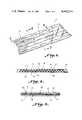
- FIG. 1is a perspective view illustrating a shielded woven cable assembly constructed according to the present invention
- FIG. 2is a sectional view taken along line 2--2 of FIG. 3;
- FIG. 3is a sectional view taken along line 3--3 of FIG. 1;
- FIG. 4is an alternate embodiment of a shielded cable assembly constructed according to the present invention wherein drain wires for draining the shield are woven into the cable in lateral alignment;
- FIG. 5is a sectional view taken along line 5--5 of FIG. 4;
- FIG. 6is a sectional view taken along line 6--6 of FIG. 4.
- the inventionrelates to a shielded woven cable assembly and method for effectively draining a metallic shield which jackets the woven cable assembly. While the invention has been illustrated in combination with a flat woven cable of a general plain weave pattern, it is to be understood that the principle of the invention may be applied to cables of many configurations and constructions.
- a woven cable Awhich includes a plurality of warp elements which includes warp conductors 10 which are electrical conductors such as insulated 28 AWG wire. Further warp elements include a plurality of warp binder yarns 14, such as Nomex nylon, interwoven with a weft filling or element 16 to form a base weave pattern with the warp conductor elements 10.
- warp conductors 10which are electrical conductors such as insulated 28 AWG wire.
- Further warp elementsinclude a plurality of warp binder yarns 14, such as Nomex nylon, interwoven with a weft filling or element 16 to form a base weave pattern with the warp conductor elements 10.
- a plurality of metallic drain wires Bwhich consist of uninsulated metal wires such as aluminum are interwoven with the base weave pattern in such a manner that a portion 18 of the drain wire is floated out of the weave pattern on one side of the cable. Another portion 20 of the drain wire is floated out on the opposite side of the base weave pattern.
- the drain wireis interwoven with the filling element 16 for example at 16a and 16b, and is floated out for four picks of the filling element on each side of the cable A.
- a metallic shield jacket C constructed from a conductive material such as aluminum foilis wrapped around and jackets the woven cable A.
- the metallic shieldcontacts the floated portions 18 and 20 of the drain wires B along generally the entire length and width of the woven cable and shield.
- the floated portions of the drain wireprovide good and effective draining of the shield jacket continuously on both sides of the shield across its width and length. Thus, electrical noise signals existing at any point in the foil shield are instantaneously drained.
- drain wiresare staggered in the weft direction of the woven cable along the length of the cable as can best be seen in FIG. 1 so as to provide good spacing of the contact location of the floated portions with the shield C.
- drain wires B'are woven in alignment in the weft direction across the width of woven cable A' along its length. Floated portions 30 and 32 are formed on opposing sides of the woven cable.
- the base weave pattern of the woven cable itselfmay be the same as that shown in FIGS. 1-3 and as described previously.
- the staggered relationship of the floated drain wires as illustrated in FIG. 1occurs by breaking the floated portions of the drain wires out at different picks of the filling element staggered along its length as is well within the skill of one in the weaving art.
- the adjacent drain wires B'are interwoven with the same pick at each break through point along the cable.
- Other staggered patterns for the drain wiresmay also be utilized such as random staggering in order to assure contact with shield C at desired locations.
- drain wiresWhile in the illustrated embodiments, five parallel drain wires have been illustrated, it is to be understood that any number of drain wires may be utilized in the cable construction as required to meet the particular application being made.
Landscapes
- Physics & Mathematics (AREA)
- Electromagnetism (AREA)
- Insulated Conductors (AREA)
Abstract
Description
Claims (8)
Priority Applications (1)
| Application Number | Priority Date | Filing Date | Title |
|---|---|---|---|
| US06/409,127US4442314A (en) | 1982-08-18 | 1982-08-18 | Shielded woven cable assembly and method of making same |
Applications Claiming Priority (1)
| Application Number | Priority Date | Filing Date | Title |
|---|---|---|---|
| US06/409,127US4442314A (en) | 1982-08-18 | 1982-08-18 | Shielded woven cable assembly and method of making same |
Publications (1)
| Publication Number | Publication Date |
|---|---|
| US4442314Atrue US4442314A (en) | 1984-04-10 |
Family
ID=23619158
Family Applications (1)
| Application Number | Title | Priority Date | Filing Date |
|---|---|---|---|
| US06/409,127Expired - Fee RelatedUS4442314A (en) | 1982-08-18 | 1982-08-18 | Shielded woven cable assembly and method of making same |
Country Status (1)
| Country | Link |
|---|---|
| US (1) | US4442314A (en) |
Cited By (15)
| Publication number | Priority date | Publication date | Assignee | Title |
|---|---|---|---|---|
| GB2161507A (en)* | 1984-07-10 | 1986-01-15 | Marling Mitronics Limited | Woven electrical ribbon cable |
| EP0175554A3 (en)* | 1984-09-14 | 1987-05-13 | Raychem Limited | Shaped woven fabrics |
| US4818820A (en)* | 1987-04-13 | 1989-04-04 | Joslyn Corporation | Transmission system |
| US4910358A (en)* | 1988-12-05 | 1990-03-20 | The Advance Group | Woven cable controlling cross-talk and impedance |
| US5308667A (en)* | 1992-10-16 | 1994-05-03 | Minnesota Mining And Manufacturing Company | Electrically conductive adhesive web |
| US5373103A (en)* | 1993-08-09 | 1994-12-13 | Woven Electronics Corp. | Ribbon electrical transmission cable with woven shielding |
| WO2000016343A1 (en)* | 1998-09-10 | 2000-03-23 | Iws International Inc. | Flat cable and its junction with an intelligent contact terminal |
| US20050054941A1 (en)* | 2003-08-22 | 2005-03-10 | Joseph Ting | Physiological monitoring garment |
| US20060228970A1 (en)* | 2005-04-07 | 2006-10-12 | Orr Lawrence W | Elastic fabric with sinusoidally disposed wires |
| US20070299325A1 (en)* | 2004-08-20 | 2007-12-27 | Brian Farrell | Physiological status monitoring system |
| US8585606B2 (en) | 2010-09-23 | 2013-11-19 | QinetiQ North America, Inc. | Physiological status monitoring system |
| US9028404B2 (en) | 2010-07-28 | 2015-05-12 | Foster-Miller, Inc. | Physiological status monitoring system |
| US9211085B2 (en) | 2010-05-03 | 2015-12-15 | Foster-Miller, Inc. | Respiration sensing system |
| US9362725B2 (en) | 2011-10-28 | 2016-06-07 | Milliken & Company | Electromagnetic shielded sleeve |
| US11006555B2 (en)* | 2016-07-19 | 2021-05-11 | Autonetworks Technologies, Ltd. | Shield member, shield member-attached electric wire, intermediate product for shield member, and method for producing shield member |
Citations (8)
| Publication number | Priority date | Publication date | Assignee | Title |
|---|---|---|---|---|
| US975358A (en)* | 1910-02-01 | 1910-11-08 | Leonard J Lewery | Electrical heater and manner of manufacturing same in the form of textiles. |
| US3476870A (en)* | 1968-01-29 | 1969-11-04 | Southern Weaving Co | Resilient foldable woven electrical cable and method |
| US3582537A (en)* | 1969-11-26 | 1971-06-01 | Haveg Industries Inc | Woven cable with bonded woven lattice structure |
| US3612743A (en)* | 1970-10-13 | 1971-10-12 | Nasa | Shielded flat cable |
| US4095042A (en)* | 1976-09-07 | 1978-06-13 | Southern Weaving Company | Woven shielded cable |
| US4158104A (en)* | 1977-06-03 | 1979-06-12 | Southern Weaving Company | Curved woven cable and method |
| EP0017077A1 (en)* | 1979-03-21 | 1980-10-15 | Siemens Aktiengesellschaft | Flat ribbon cable shielded on both sides and foil-insulated |
| US4281211A (en)* | 1979-04-13 | 1981-07-28 | Southern Weaving Company | Woven cover for electrical transmission cable |
- 1982
- 1982-08-18USUS06/409,127patent/US4442314A/ennot_activeExpired - Fee Related
Patent Citations (8)
| Publication number | Priority date | Publication date | Assignee | Title |
|---|---|---|---|---|
| US975358A (en)* | 1910-02-01 | 1910-11-08 | Leonard J Lewery | Electrical heater and manner of manufacturing same in the form of textiles. |
| US3476870A (en)* | 1968-01-29 | 1969-11-04 | Southern Weaving Co | Resilient foldable woven electrical cable and method |
| US3582537A (en)* | 1969-11-26 | 1971-06-01 | Haveg Industries Inc | Woven cable with bonded woven lattice structure |
| US3612743A (en)* | 1970-10-13 | 1971-10-12 | Nasa | Shielded flat cable |
| US4095042A (en)* | 1976-09-07 | 1978-06-13 | Southern Weaving Company | Woven shielded cable |
| US4158104A (en)* | 1977-06-03 | 1979-06-12 | Southern Weaving Company | Curved woven cable and method |
| EP0017077A1 (en)* | 1979-03-21 | 1980-10-15 | Siemens Aktiengesellschaft | Flat ribbon cable shielded on both sides and foil-insulated |
| US4281211A (en)* | 1979-04-13 | 1981-07-28 | Southern Weaving Company | Woven cover for electrical transmission cable |
Cited By (18)
| Publication number | Priority date | Publication date | Assignee | Title |
|---|---|---|---|---|
| GB2161507A (en)* | 1984-07-10 | 1986-01-15 | Marling Mitronics Limited | Woven electrical ribbon cable |
| EP0175554A3 (en)* | 1984-09-14 | 1987-05-13 | Raychem Limited | Shaped woven fabrics |
| US4818820A (en)* | 1987-04-13 | 1989-04-04 | Joslyn Corporation | Transmission system |
| US4910358A (en)* | 1988-12-05 | 1990-03-20 | The Advance Group | Woven cable controlling cross-talk and impedance |
| US5308667A (en)* | 1992-10-16 | 1994-05-03 | Minnesota Mining And Manufacturing Company | Electrically conductive adhesive web |
| US5373103A (en)* | 1993-08-09 | 1994-12-13 | Woven Electronics Corp. | Ribbon electrical transmission cable with woven shielding |
| WO2000016343A1 (en)* | 1998-09-10 | 2000-03-23 | Iws International Inc. | Flat cable and its junction with an intelligent contact terminal |
| US20100041974A1 (en)* | 2003-08-22 | 2010-02-18 | Joseph Ting | Physiological monitoring garment |
| US7559902B2 (en) | 2003-08-22 | 2009-07-14 | Foster-Miller, Inc. | Physiological monitoring garment |
| US20050054941A1 (en)* | 2003-08-22 | 2005-03-10 | Joseph Ting | Physiological monitoring garment |
| US20070299325A1 (en)* | 2004-08-20 | 2007-12-27 | Brian Farrell | Physiological status monitoring system |
| US20060228970A1 (en)* | 2005-04-07 | 2006-10-12 | Orr Lawrence W | Elastic fabric with sinusoidally disposed wires |
| US7337810B2 (en) | 2005-04-07 | 2008-03-04 | Woven Electronics Corporation | Elastic fabric with sinusoidally disposed wires |
| US9211085B2 (en) | 2010-05-03 | 2015-12-15 | Foster-Miller, Inc. | Respiration sensing system |
| US9028404B2 (en) | 2010-07-28 | 2015-05-12 | Foster-Miller, Inc. | Physiological status monitoring system |
| US8585606B2 (en) | 2010-09-23 | 2013-11-19 | QinetiQ North America, Inc. | Physiological status monitoring system |
| US9362725B2 (en) | 2011-10-28 | 2016-06-07 | Milliken & Company | Electromagnetic shielded sleeve |
| US11006555B2 (en)* | 2016-07-19 | 2021-05-11 | Autonetworks Technologies, Ltd. | Shield member, shield member-attached electric wire, intermediate product for shield member, and method for producing shield member |
Similar Documents
| Publication | Publication Date | Title |
|---|---|---|
| US4442314A (en) | Shielded woven cable assembly and method of making same | |
| US4487992A (en) | Shielded electrical cable | |
| US4095042A (en) | Woven shielded cable | |
| US3447120A (en) | Woven high-frequency transmission line | |
| CA1166711A (en) | Electric cables with a single insulating shielding member | |
| US4619487A (en) | Flat cable connector with grounding clip | |
| US5391836A (en) | Electric cable | |
| US4229615A (en) | Round/flat woven multi-conductor cable | |
| US4818820A (en) | Transmission system | |
| EP0068665B1 (en) | Shielded electrical cable | |
| US4712298A (en) | Flat woven cable for insulation displaceable connector termination and method | |
| US4731031A (en) | Transmission cable connector having a contoured shell | |
| US4624515A (en) | Electrical connector with grounding clip | |
| EP0073622A3 (en) | A multiconductor coaxial cable assembly | |
| US5900587A (en) | Daisy chain cable assembly and method for manufacture | |
| JPH09237656A (en) | Ground strengthening type electric connector | |
| US5021007A (en) | Screened flat electric cable having a plurality of parallel conductors | |
| WO1991019334A1 (en) | Shielded connectors for shielded cables | |
| JPS61126782A (en) | Connector for shielded flat cable | |
| EP0687037A1 (en) | Shielding arrangement between several shielding cables and a connector | |
| US4967040A (en) | Screened electric cable provided with zones for rapid parallel connection | |
| US4981442A (en) | Electrical harness | |
| EP0373120A1 (en) | Coaxial cable and making method therefor | |
| CN1071946C (en) | Junction box for multiple shielded cables | |
| US12261397B2 (en) | Electrical connector with easier manufacturing and assembly |
Legal Events
| Date | Code | Title | Description |
|---|---|---|---|
| AS | Assignment | Owner name:SOUTHERN WEAVING COMPANY, P.O. BOX 367, GREENVILLE Free format text:ASSIGNMENT OF ASSIGNORS INTEREST.;ASSIGNOR:PIPER, DOUGLAS E.;REEL/FRAME:004036/0598 Effective date:19820812 | |
| AS | Assignment | Owner name:SW INVESTMENT CORPORATION Free format text:CHANGE OF NAME;ASSIGNOR:SOUTHERN WEAVING COMPANY;REEL/FRAME:004197/0749 Effective date:19830712 Owner name:WOVEN ELECTRONICS CORPORATION, MAULDIN, SC 29662 Free format text:ASSIGNMENT OF ASSIGNORS INTEREST.;ASSIGNOR:SW INVESTMENT CORPORATION;REEL/FRAME:004197/0743 Effective date:19831024 | |
| AS | Assignment | Owner name:BARCLAYSAMERICAN/BUSINESS CREDIT, INC., 129 WEST T Free format text:ASIGNS THE ENTIRE INTEREST SUBJECT TO LICENSE RECITED;ASSIGNOR:WOVEN ELECTRONICS CORPORATION;REEL/FRAME:004305/0596 Effective date:19840710 | |
| REMI | Maintenance fee reminder mailed | ||
| LAPS | Lapse for failure to pay maintenance fees | ||
| STCH | Information on status: patent discontinuation | Free format text:PATENT EXPIRED DUE TO NONPAYMENT OF MAINTENANCE FEES UNDER 37 CFR 1.362 | |
| FP | Lapsed due to failure to pay maintenance fee | Effective date:19880410 |