US4441071A - Temperature compensation circuit for thermocouples - Google Patents
Temperature compensation circuit for thermocouplesDownload PDFInfo
- Publication number
- US4441071A US4441071AUS06/364,080US36408082AUS4441071AUS 4441071 AUS4441071 AUS 4441071AUS 36408082 AUS36408082 AUS 36408082AUS 4441071 AUS4441071 AUS 4441071A
- Authority
- US
- United States
- Prior art keywords
- voltage
- temperature
- thermocouple
- source
- output terminal
- Prior art date
- Legal status (The legal status is an assumption and is not a legal conclusion. Google has not performed a legal analysis and makes no representation as to the accuracy of the status listed.)
- Expired - Fee Related
Links
Images
Classifications
- G—PHYSICS
- G01—MEASURING; TESTING
- G01R—MEASURING ELECTRIC VARIABLES; MEASURING MAGNETIC VARIABLES
- G01R17/00—Measuring arrangements involving comparison with a reference value, e.g. bridge
- G01R17/02—Arrangements in which the value to be measured is automatically compared with a reference value
- G—PHYSICS
- G01—MEASURING; TESTING
- G01K—MEASURING TEMPERATURE; MEASURING QUANTITY OF HEAT; THERMALLY-SENSITIVE ELEMENTS NOT OTHERWISE PROVIDED FOR
- G01K7/00—Measuring temperature based on the use of electric or magnetic elements directly sensitive to heat ; Power supply therefor, e.g. using thermoelectric elements
- G01K7/02—Measuring temperature based on the use of electric or magnetic elements directly sensitive to heat ; Power supply therefor, e.g. using thermoelectric elements using thermoelectric elements, e.g. thermocouples
- G01K7/10—Arrangements for compensating for auxiliary variables, e.g. length of lead
- G01K7/12—Arrangements with respect to the cold junction, e.g. preventing influence of temperature of surrounding air
- G01K7/13—Circuits for cold-junction compensation
Definitions
- This inventionrelates to a temperature compensation circuit for use with thermocouples operated with a reference junction at ambient temperature. More particularly the circuit provides compensation for variations in thermocouple output induced by variations in ambient temperature.
- thermocouplesare well known in the field of temperature measurement and are frequently employed where there is a need for a fast responding, compact and inexpensive temperature sensor.
- An important characteristic of thermocouplesis that they produce an output signal relative to two temperatures: a measurement temperature, and a reference temperature. This is so, because a thermocouple is basically a closed loop circuit formed by two different metals. The two points at which the metals join are called "junctions.” One junction is designated as the “measuring” junction and the other junction is designated as the "reference” junction. When these junctions are immersed in differing temperature environments, an EMF is developed in the thermocouple.
- thermocoupleIn the traditional manner of use, the reference junction of a thermocouple is kept immersed in an ice water bath.
- the ice water bathserves as a simple temperature reference which is stable and repeatable.
- EMF measuring instrumentBy inserting an EMF measuring instrument into the thermocouple loop, the thermocouple output signal is measured and may be converted into a temperature reading.
- thermocoupleAs a rule, the variation of ambient temperature to which an indicating instrument is subjected is limited to a range comfortably tolerated by the user of the instrument. Thus, a compensation system, unlike a thermocouple, need function only over a relatively narrow range of temperatures. Fortunately, most thermocouples and other temperature responsive devices are quite linear over such a limited temperature range. Accordingly, the essential requirement of the compensation system is that it provide an output voltage linearly proportional to the ambient temperature, passing through zero volts at zero degrees Celsius (0° C.).
- thermocoupleAccordingly, there is disclosed an improved method and circuitry for compensating the temperature reading of a thermocouple wherein the aforesaid shortcomings of the prior art are overcome.
- the present inventionis directed to a circuit for generating a voltage for compensating the output of a thermocouple.
- the thermocouplehas at least one reference junction and a measuring junction and compensation is provided to enable the thermocouple to be operated with its reference junction at ambient temperature.
- the compensation voltagevaries linearly with changes in the ambient temperature and passes through zero volts at 0° C.
- a first source of constant potentialis applied through a variable resistor across at least one semiconductor device developing a voltage thereacross in a forward biased direction.
- the developed voltageis divided by a first voltage dividing means.
- a second source of constant potential of opposite polarityis divided by a second voltage dividing means.
- the divided voltage of the first voltage dividing means and the divided voltage of the second voltage dividing meansare combined at an output terminal.
- the combined voltage at the output terminalhas a temperature coefficient corresponding to a selected thermocouple type over a selected temperature range.
- variable resistoris adjusted to set the combined voltage at the output terminal to a level corresponding to the output of the selected thermocouple type when the measuring junction thereof is at an equivalent temperature and at least one reference junction thereof is at 0° C.
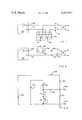
- FIG. 1is a schematic representation of a thermocouple having two reference junctions immersed in an ice water bath, and connected to a temperature indicating instrument, and connected to a temperature indicating instrument.
- FIG. 2is a schematic representation of a thermocouple having two reference junctions at ambient temperature connected to the thermocouple compensation circuit of the invention, and a temperature indicating instrument.
- FIG. 3is a schematic diagram of the thermocouple cmpensation circuit of the invention.
- a typical temperature measuring deviceincludes a thermocouple 10 constructed of metal wire A and metal wire B, both of which are joined at one end to form measuring junction 12 which is immersed in a temperature environment 14.
- the other end of metal wire Aforms a reference junction 16 with copper wire 22 which is connected to temperature indicating instrument 26.
- metal wire Bforms a reference junction 18 with copper wire 24 connected to temperature indicating instrument 26.
- Reference junctions 16 and 18are immersed in an ice water bath 20.
- thermocouple 10is shown as before, except that metal wire A forms a reference junction 28 with copper wire 34 which is connected to compensation circuit 30. Also, metal wire B of thermocouple 10 forms a reference junction 32 with copper wire 36 which is connected to an input of temperature indicating instrument 26. A copper wire 38 connects compensation circuit 30 to an input of temperature indicating instrument 26.
- the ambient temperatureis 25° C.
- that temperature environment 14is 125° C.
- a 100° temperature difference between the measuring junction 12 and the reference junctions 28 and 32Taking a type K thermocouple (chromel/alumel), as an example, an EMF would be developed corresponding to 40 ⁇ V/°C. or a total of 4 mV would be developed.
- the compensation circuit 30would be calibrated to generate 40 ⁇ V/°C. or 1 mV at 25° C. which is placed in series with the 4 mV output of the thermocouple.
- the input to the temperature indicating instrument 26would be 5 mV which corresponds to the output of this thermocouple type when used with an ice water reference.
- FIG. 3there is shown a schematic diagram of the compensation circuit of the invention, generally denoted by reference numeral 30.
- a variable resistor 40is connected to the base-to-emitter junctions of series connected transistors 42 and 44.
- a first source of constant potential 41is connected across variable resistor 40 and transistors 42 and 44 causing a constant current to flow therethrough.
- the setting of variable resistor 40determines the amplitude of this current and therefore the voltage which is developed in a forward biased direction across the base-to-emitter junction of transistors 42 and 44.
- the developed voltageis fed into a first voltage divider formed by resistors 45 and 47.
- resistors 45 and 47there is connected an output terminal 48. Also connected to output terminal 48 is one end of resistor 46 which, in conjunction with resistor 47, forms a second voltage divider. A second source of constant potential 43, which is of opposite polarity to source 41, is connected to the other end of resistor 46.
- the arrangementis such that the divided voltage of the first source 41 and the divided voltage of the second source 43 are combined at output terminal 48.
- the voltageis temperature variable according to the voltage temperature coefficient of the specific semiconductor type. It has been found that for a type 2N5088 transistor using a current flow in the region of 0.8 ⁇ A, the change in base-to-emitter voltage ( ⁇ V BE ) is approximately 2.5 mV/°C.
- the amplitude of the first divided voltageis adjusted by means of variable resistor 40 so that at a temperature of 0° C. it will be equal and opposite to the second divided voltage. The sum of these voltages at output terminal 48, therefore, would equal zero at 0° C.
- this single calibration of the output of the compensation circuitcan be made at a convenient room temperature.
- a group of 41 circuit units using Type 2N5088 transistors produced by two different manufacturers and having several different dates of manufacturewere found to have, under conditions of constant current and temperature, measured variation or spread in forward voltage (V BE ) of 4%. After varying the current to obtain a specified V BE , a reduction was obtained in TEMPCO spread from 3.6% to 1.2%.
Landscapes
- Physics & Mathematics (AREA)
- General Physics & Mathematics (AREA)
- Indication And Recording Devices For Special Purposes And Tariff Metering Devices (AREA)
Abstract
Description
______________________________________ Reference Numeral Name of Component Value ______________________________________ 40 Variable Resistor 2.3Mohms 46 Resistor 1.405Mohms 46 Resistor 1.53Mohms 47 Resistor 12.24K ohms 42Transistor 2N5088 44Transistor 2N5088 41 Potential Source -1.52volts 43 Potential Source +1.2 volts ______________________________________
Claims (5)
Priority Applications (1)
| Application Number | Priority Date | Filing Date | Title |
|---|---|---|---|
| US06/364,080US4441071A (en) | 1982-03-31 | 1982-03-31 | Temperature compensation circuit for thermocouples |
Applications Claiming Priority (1)
| Application Number | Priority Date | Filing Date | Title |
|---|---|---|---|
| US06/364,080US4441071A (en) | 1982-03-31 | 1982-03-31 | Temperature compensation circuit for thermocouples |
Publications (1)
| Publication Number | Publication Date |
|---|---|
| US4441071Atrue US4441071A (en) | 1984-04-03 |
Family
ID=23432919
Family Applications (1)
| Application Number | Title | Priority Date | Filing Date |
|---|---|---|---|
| US06/364,080Expired - Fee RelatedUS4441071A (en) | 1982-03-31 | 1982-03-31 | Temperature compensation circuit for thermocouples |
Country Status (1)
| Country | Link |
|---|---|
| US (1) | US4441071A (en) |
Cited By (4)
| Publication number | Priority date | Publication date | Assignee | Title |
|---|---|---|---|---|
| US4624582A (en)* | 1984-02-29 | 1986-11-25 | Banda Lionel A | Multi-wire mineral insulated cable thermocouple reference junction |
| US6342997B1 (en)* | 1998-02-11 | 2002-01-29 | Therm-O-Disc, Incorporated | High sensitivity diode temperature sensor with adjustable current source |
| KR20030046606A (en)* | 2001-12-06 | 2003-06-18 | 삼성전자주식회사 | Apparatus for correcting temperature of thermocouple and method for correcting using the same |
| US20090315607A1 (en)* | 2006-06-22 | 2009-12-24 | Kalina Roger J | Programmable circuit for drift compensation |
Citations (14)
| Publication number | Priority date | Publication date | Assignee | Title |
|---|---|---|---|---|
| US3092998A (en)* | 1960-08-08 | 1963-06-11 | Rca Corp | Thermometers |
| US3102425A (en)* | 1962-03-14 | 1963-09-03 | Ontario Research Foundation | Method and apparatus for temperature integrating |
| US3271660A (en)* | 1963-03-28 | 1966-09-06 | Fairchild Camera Instr Co | Reference voltage source |
| US3281656A (en)* | 1963-07-02 | 1966-10-25 | Nuclear Corp Of America | Semiconductor breakdown diode temperature compensation |
| US3330158A (en)* | 1965-07-12 | 1967-07-11 | Diode Corp Comp | Solid state temperature measuring device |
| US3420104A (en)* | 1966-05-26 | 1969-01-07 | Bell Telephone Labor Inc | Temperature measuring apparatus using semiconductor junction |
| US3440883A (en)* | 1966-12-01 | 1969-04-29 | Monsanto Co | Electronic semiconductor thermometer |
| US3461380A (en)* | 1967-08-24 | 1969-08-12 | Du Pont | Thermocouple reference junction compensating circuits |
| US3722283A (en)* | 1971-11-17 | 1973-03-27 | Kettering Scient Res Inc | Linear reading thermometer |
| US3808469A (en)* | 1972-10-27 | 1974-04-30 | Bell & Howell Co | Temperature compensation circuit for sensor of physical variables such as temperature and pressure |
| US3831042A (en)* | 1972-10-27 | 1974-08-20 | Bell & Howell Co | Temperature compensation circuit for sensor of physical variables such as temperature and pressure |
| US3916691A (en)* | 1973-03-26 | 1975-11-04 | Omega Engineering | Electrically actuated cold junction compensating device |
| US3967188A (en)* | 1973-05-24 | 1976-06-29 | Bell & Howell Company | Temperature compensation circuit for sensor of physical variables such as temperature and pressure |
| US4133700A (en)* | 1975-03-13 | 1979-01-09 | Omega Engineering Inc. | Cold junction thermocouple compensator |
- 1982
- 1982-03-31USUS06/364,080patent/US4441071A/ennot_activeExpired - Fee Related
Patent Citations (14)
| Publication number | Priority date | Publication date | Assignee | Title |
|---|---|---|---|---|
| US3092998A (en)* | 1960-08-08 | 1963-06-11 | Rca Corp | Thermometers |
| US3102425A (en)* | 1962-03-14 | 1963-09-03 | Ontario Research Foundation | Method and apparatus for temperature integrating |
| US3271660A (en)* | 1963-03-28 | 1966-09-06 | Fairchild Camera Instr Co | Reference voltage source |
| US3281656A (en)* | 1963-07-02 | 1966-10-25 | Nuclear Corp Of America | Semiconductor breakdown diode temperature compensation |
| US3330158A (en)* | 1965-07-12 | 1967-07-11 | Diode Corp Comp | Solid state temperature measuring device |
| US3420104A (en)* | 1966-05-26 | 1969-01-07 | Bell Telephone Labor Inc | Temperature measuring apparatus using semiconductor junction |
| US3440883A (en)* | 1966-12-01 | 1969-04-29 | Monsanto Co | Electronic semiconductor thermometer |
| US3461380A (en)* | 1967-08-24 | 1969-08-12 | Du Pont | Thermocouple reference junction compensating circuits |
| US3722283A (en)* | 1971-11-17 | 1973-03-27 | Kettering Scient Res Inc | Linear reading thermometer |
| US3808469A (en)* | 1972-10-27 | 1974-04-30 | Bell & Howell Co | Temperature compensation circuit for sensor of physical variables such as temperature and pressure |
| US3831042A (en)* | 1972-10-27 | 1974-08-20 | Bell & Howell Co | Temperature compensation circuit for sensor of physical variables such as temperature and pressure |
| US3916691A (en)* | 1973-03-26 | 1975-11-04 | Omega Engineering | Electrically actuated cold junction compensating device |
| US3967188A (en)* | 1973-05-24 | 1976-06-29 | Bell & Howell Company | Temperature compensation circuit for sensor of physical variables such as temperature and pressure |
| US4133700A (en)* | 1975-03-13 | 1979-01-09 | Omega Engineering Inc. | Cold junction thermocouple compensator |
Cited By (5)
| Publication number | Priority date | Publication date | Assignee | Title |
|---|---|---|---|---|
| US4624582A (en)* | 1984-02-29 | 1986-11-25 | Banda Lionel A | Multi-wire mineral insulated cable thermocouple reference junction |
| US6342997B1 (en)* | 1998-02-11 | 2002-01-29 | Therm-O-Disc, Incorporated | High sensitivity diode temperature sensor with adjustable current source |
| KR20030046606A (en)* | 2001-12-06 | 2003-06-18 | 삼성전자주식회사 | Apparatus for correcting temperature of thermocouple and method for correcting using the same |
| US20090315607A1 (en)* | 2006-06-22 | 2009-12-24 | Kalina Roger J | Programmable circuit for drift compensation |
| US8123405B2 (en)* | 2006-06-22 | 2012-02-28 | Bae Systems Information Solutions Inc. | Programmable circuit for drift compensation |
Similar Documents
| Publication | Publication Date | Title |
|---|---|---|
| EP0725923B1 (en) | Two terminal temperature transducer having circuitry which controls the entire operating current to be linearly proportional with temperature | |
| KR100197821B1 (en) | Hall sensor automatically compensated | |
| US5550469A (en) | Hall-effect device driver with temperature-dependent sensitivity compensation | |
| US4123698A (en) | Integrated circuit two terminal temperature transducer | |
| US6789939B2 (en) | Temperature sensor and method for operating a temperature sensor | |
| US10788851B2 (en) | Self-biased temperature-compensated Zener reference | |
| US3688581A (en) | Device for correcting the non-linear variation of a signal as a function of a measured magnitude | |
| US3092998A (en) | Thermometers | |
| US4120201A (en) | Thermocouple temperature measurement circuit having cold junction compensation | |
| US9429605B2 (en) | Techniques for determining a resistance value | |
| JPS6038619A (en) | Air flow sensing circuit | |
| US7857510B2 (en) | Temperature sensing circuit | |
| US5419637A (en) | Method and apparatus for measuring temperature using an inherently calibrated p-n junction-type temperature sensor | |
| US3420104A (en) | Temperature measuring apparatus using semiconductor junction | |
| US6946825B2 (en) | Bandgap voltage generator with a bipolar assembly and a mirror assembly | |
| CA1079091A (en) | Linearized thermistor temperature measuring circuit | |
| US3805616A (en) | Temperature measuring apparatus | |
| US3934476A (en) | Linear telethermometer | |
| US4441071A (en) | Temperature compensation circuit for thermocouples | |
| US5889394A (en) | Temperature independent current reference | |
| US3076339A (en) | Thermometer | |
| US3461380A (en) | Thermocouple reference junction compensating circuits | |
| CN118190202A (en) | Integrated circuit including temperature sensor | |
| US3100397A (en) | Pyrometer apparatus | |
| US5096303A (en) | Electronic circuit arrangement for temperature measurement based on a platinum resistor as a temperature sensing resistor |
Legal Events
| Date | Code | Title | Description |
|---|---|---|---|
| AS | Assignment | Owner name:BECKMAN INSTRUMENTS, INC. A CORP. OF CA Free format text:ASSIGNMENT OF ASSIGNORS INTEREST.;ASSIGNOR:HOUSEMAN, ROBIN D.;REEL/FRAME:003981/0320 Effective date:19820330 | |
| FEPP | Fee payment procedure | Free format text:MAINTENANCE FEE REMINDER MAILED (ORIGINAL EVENT CODE: REM.); ENTITY STATUS OF PATENT OWNER: LARGE ENTITY | |
| FEPP | Fee payment procedure | Free format text:SURCHARGE FOR LATE PAYMENT, PL 96-517 (ORIGINAL EVENT CODE: M176); ENTITY STATUS OF PATENT OWNER: LARGE ENTITY | |
| MAFP | Maintenance fee payment | Free format text:PAYMENT OF MAINTENANCE FEE, 4TH YEAR, PL 96-517 (ORIGINAL EVENT CODE: M170); ENTITY STATUS OF PATENT OWNER: LARGE ENTITY Year of fee payment:4 | |
| FEPP | Fee payment procedure | Free format text:PAYOR NUMBER ASSIGNED (ORIGINAL EVENT CODE: ASPN); ENTITY STATUS OF PATENT OWNER: LARGE ENTITY | |
| AS | Assignment | Owner name:ROSEMOUNT INC., MINNESOTA Free format text:ASSIGNMENT OF ASSIGNORS INTEREST.;ASSIGNOR:BECKMAN INDUSTRIAL CORPORATION;REEL/FRAME:005243/0057 Effective date:19890523 Owner name:ROSEMOUNT INC., MINNESOTA Free format text:ASSIGNMENT OF ASSIGNORS INTEREST;ASSIGNOR:BECKMAN INDUSTRIAL CORPORATION;REEL/FRAME:005243/0057 Effective date:19890523 | |
| FEPP | Fee payment procedure | Free format text:PAYOR NUMBER ASSIGNED (ORIGINAL EVENT CODE: ASPN); ENTITY STATUS OF PATENT OWNER: LARGE ENTITY Free format text:PAYER NUMBER DE-ASSIGNED (ORIGINAL EVENT CODE: RMPN); ENTITY STATUS OF PATENT OWNER: LARGE ENTITY | |
| MAFP | Maintenance fee payment | Free format text:PAYMENT OF MAINTENANCE FEE, 8TH YEAR, PL 96-517 (ORIGINAL EVENT CODE: M171); ENTITY STATUS OF PATENT OWNER: LARGE ENTITY Year of fee payment:8 | |
| FEPP | Fee payment procedure | Free format text:MAINTENANCE FEE REMINDER MAILED (ORIGINAL EVENT CODE: REM.); ENTITY STATUS OF PATENT OWNER: LARGE ENTITY | |
| LAPS | Lapse for failure to pay maintenance fees | ||
| FP | Lapsed due to failure to pay maintenance fee | Effective date:19960403 | |
| STCH | Information on status: patent discontinuation | Free format text:PATENT EXPIRED DUE TO NONPAYMENT OF MAINTENANCE FEES UNDER 37 CFR 1.362 |