US4440727A - Tubular furnace for performance of gas reactions - Google Patents
Tubular furnace for performance of gas reactionsDownload PDFInfo
- Publication number
- US4440727A US4440727AUS06/408,827US40882782AUS4440727AUS 4440727 AUS4440727 AUS 4440727AUS 40882782 AUS40882782 AUS 40882782AUS 4440727 AUS4440727 AUS 4440727A
- Authority
- US
- United States
- Prior art keywords
- flue gas
- recuperator
- furnace
- chamber
- heating
- Prior art date
- Legal status (The legal status is an assumption and is not a legal conclusion. Google has not performed a legal analysis and makes no representation as to the accuracy of the status listed.)
- Expired - Fee Related
Links
- 238000006243chemical reactionMethods0.000titleclaimsabstractdescription15
- 238000010438heat treatmentMethods0.000claimsabstractdescription28
- 239000000919ceramicSubstances0.000claimsabstractdescription8
- LELOWRISYMNNSU-UHFFFAOYSA-Nhydrogen cyanideChemical compoundN#CLELOWRISYMNNSU-UHFFFAOYSA-N0.000claimsabstractdescription8
- 238000004519manufacturing processMethods0.000claimsabstractdescription5
- 239000003546flue gasSubstances0.000claimsdescription28
- UGFAIRIUMAVXCW-UHFFFAOYSA-NCarbon monoxideChemical compound[O+]#[C-]UGFAIRIUMAVXCW-UHFFFAOYSA-N0.000claimsdescription23
- 239000002184metalSubstances0.000claimsdescription3
- 238000010276constructionMethods0.000abstractdescription7
- 238000000034methodMethods0.000abstractdescription6
- QYIOIRWGBBLMOG-UHFFFAOYSA-Nazane formonitrile methaneChemical compoundN.C.C#NQYIOIRWGBBLMOG-UHFFFAOYSA-N0.000abstractdescription2
- 239000007789gasSubstances0.000description6
- 238000002485combustion reactionMethods0.000description5
- 230000007704transitionEffects0.000description3
- 230000000712assemblyEffects0.000description2
- 238000000429assemblyMethods0.000description2
- 239000000463materialSubstances0.000description2
- 239000011449brickSubstances0.000description1
- 238000001816coolingMethods0.000description1
- 230000002349favourable effectEffects0.000description1
- 239000002918waste heatSubstances0.000description1
Images

Classifications
- C—CHEMISTRY; METALLURGY
- C01—INORGANIC CHEMISTRY
- C01C—AMMONIA; CYANOGEN; COMPOUNDS THEREOF
- C01C3/00—Cyanogen; Compounds thereof
- C01C3/02—Preparation, separation or purification of hydrogen cyanide
- C01C3/0208—Preparation in gaseous phase
- C01C3/0229—Preparation in gaseous phase from hydrocarbons and ammonia in the absence of oxygen, e.g. HMA-process
- C01C3/0233—Preparation in gaseous phase from hydrocarbons and ammonia in the absence of oxygen, e.g. HMA-process making use of fluidised beds, e.g. the Shawinigan-process
- B—PERFORMING OPERATIONS; TRANSPORTING
- B01—PHYSICAL OR CHEMICAL PROCESSES OR APPARATUS IN GENERAL
- B01J—CHEMICAL OR PHYSICAL PROCESSES, e.g. CATALYSIS OR COLLOID CHEMISTRY; THEIR RELEVANT APPARATUS
- B01J19/00—Chemical, physical or physico-chemical processes in general; Their relevant apparatus
- B01J19/0006—Controlling or regulating processes
- B01J19/0013—Controlling the temperature of the process
- B—PERFORMING OPERATIONS; TRANSPORTING
- B01—PHYSICAL OR CHEMICAL PROCESSES OR APPARATUS IN GENERAL
- B01J—CHEMICAL OR PHYSICAL PROCESSES, e.g. CATALYSIS OR COLLOID CHEMISTRY; THEIR RELEVANT APPARATUS
- B01J2219/00—Chemical, physical or physico-chemical processes in general; Their relevant apparatus
- B01J2219/00049—Controlling or regulating processes
- B01J2219/00051—Controlling the temperature
- B01J2219/0015—Controlling the temperature by thermal insulation means
- B01J2219/00155—Controlling the temperature by thermal insulation means using insulating materials or refractories
- B—PERFORMING OPERATIONS; TRANSPORTING
- B01—PHYSICAL OR CHEMICAL PROCESSES OR APPARATUS IN GENERAL
- B01J—CHEMICAL OR PHYSICAL PROCESSES, e.g. CATALYSIS OR COLLOID CHEMISTRY; THEIR RELEVANT APPARATUS
- B01J2219/00—Chemical, physical or physico-chemical processes in general; Their relevant apparatus
- B01J2219/00049—Controlling or regulating processes
- B01J2219/00051—Controlling the temperature
- B01J2219/00157—Controlling the temperature by means of a burner
- B—PERFORMING OPERATIONS; TRANSPORTING
- B01—PHYSICAL OR CHEMICAL PROCESSES OR APPARATUS IN GENERAL
- B01J—CHEMICAL OR PHYSICAL PROCESSES, e.g. CATALYSIS OR COLLOID CHEMISTRY; THEIR RELEVANT APPARATUS
- B01J2219/00—Chemical, physical or physico-chemical processes in general; Their relevant apparatus
- B01J2219/00049—Controlling or regulating processes
- B01J2219/00051—Controlling the temperature
- B01J2219/00159—Controlling the temperature controlling multiple zones along the direction of flow, e.g. pre-heating and after-cooling
- Y—GENERAL TAGGING OF NEW TECHNOLOGICAL DEVELOPMENTS; GENERAL TAGGING OF CROSS-SECTIONAL TECHNOLOGIES SPANNING OVER SEVERAL SECTIONS OF THE IPC; TECHNICAL SUBJECTS COVERED BY FORMER USPC CROSS-REFERENCE ART COLLECTIONS [XRACs] AND DIGESTS
- Y02—TECHNOLOGIES OR APPLICATIONS FOR MITIGATION OR ADAPTATION AGAINST CLIMATE CHANGE
- Y02P—CLIMATE CHANGE MITIGATION TECHNOLOGIES IN THE PRODUCTION OR PROCESSING OF GOODS
- Y02P20/00—Technologies relating to chemical industry
- Y02P20/10—Process efficiency
- Y02P20/129—Energy recovery, e.g. by cogeneration, H2recovery or pressure recovery turbines
Definitions
- the inventionis directed to a tube furnace for the performance gas reactions, especially for the production of hydrocyanic acid according to the BMA process (hydrocyanic acid-methane-ammonia process), in which the individual structural parts in consideration of energy and industrial safety aspects are arranged in a special way to each other and besides each other.
- the previously known type furnaces for the performance gas reactionsespecially at temperatures above 900° C., for example at temperatures between 1000° C. and 1500° C. consist of a series of parallel connected heating chambers which are mounted with freely suspended ceramic tubes or tube assemblies. Each of these chambers is heated separately.
- the flue gas dischargetakes place via a separate branch channel which is joined via transition pieces with the individual chambers.
- the vertically arranged ceramic tubeswhose inside represents the actual reaction space, are supplied with the necessary heat for the reaction through the tube walls so that the heating chambers accordingly must be lined with a temperature resistant material.
- the heatis produced by gas or oil burners.
- the combustion airis heated recuperatively.
- the burners, of which 2 elements are needed per chamber,are arranged in the lower region of the chamber in order that the entire length of the reaction tubes as far as possible can be brought to the required reaction temperature.
- the heat of the departing flue gasescan be used for preheating the air and/or for producing the steam.
- recuperators for the preheating of the combustion airare in each case arranged between two chambers and are heated simultaneously with the reaction tubes (German Pat. No. 1,041,476 and related Endter U.S. Pat. No. 2,987,382. The entire disclosure of Endter is hereby incorporated by reference and relied upon).
- a further disadvantage of this known furnaceis its quite large outer surface which leads to energy losses.
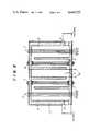
- FIG. 1is a schematically drawn cross section of the furnace through a twin heating chamber and the component parts;
- FIG. 2shows an alternative construction
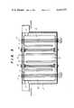
- FIG. 3shows still another form of the furnace.
- the subject matter of the inventionis a tube furnace for the performance of gas reactions, especially for the production of hydrocyanic acid according to the BMA process, in ceramic tube assemblies which are freely suspended within the furnace in heating chambers and whereby the furnace contains as essential parts, burner a flue gas-branch channel and recuperators which is characterized by the furnace being essentially of a masonry block or cube 1 walled construction with a metal construction on the outside, with at least two twin type furnaces arranged next to each other, the furnace containing, in the form of a structural unit, the ceramic tube assembly heating chambers 2 arranged with recuperator spaces 3 having recuperators 4 and joined to the middle of the furnace as well as a flue gas branch channel 5 aranged between the two recuperator spaces 3 and whereby each heating chamber 2 has a maximum of only one burner 9.
- a favorable development of the process of the inventioncomprises the provision of flue gas conduits 7 between the heating chamber 2 and the recuperator spaces 3 having control members 6.
- the flue gas conduitspreferably receive the flue gases of the heating chamber in the vicinity of the upper furnace cover and preferably introduce these gases from below into the recuperator spaces.
- a further improvementis produced by so dimensioning and arranging the recuperator spaces 3 as well as the recuperator components that they provide for one or more adjacently arranged heating chambers 2.
- FIG. 1is a schematically drawn cross section of the furnace through a twin chamber and the component parts. It should be recognized that under the twin type arrangement there is provided a Janus head type arrangment.
- the drawing 1indicates the building block or cube shaped formed entire furnace consisting of the brick lining with temperature resistant, fire proof material and a jacket, for example of sheet metal; 2 indicates the heating chambers, 3 a recuperator space with the recuperator component 4, 5 the flue gas branch channel, 7 the flue gas conduits and 6 the control members for the flue gas conduits, which controls are known per se, 8 represents the ceramic reaction tubes and 9 the burner.
- This type of twin unitis able to be arranged in any number in series in succession. For one manner of mounting the tubes, see the aforementioned Endter U.S. Pat. No. 2,987,382.
- FIG. 2A further development of the form of the furnace of the invention is shown in FIG. 2.
- the reference numeralshave the same meaning as in FIG. 1.
- FIG. 3a development of the furnace of the invention in which as well as in FIG. 2, the flue gas conduits 7 are omitted and the burners 9 are arranged in the upper part of the heating chamber 2, so that the heating of the tube assembly is carried out in counterflow manner.
- the fule gases of the heating chamber 2in this case are drawn off in the vicinity of the lower bottom plate and the recuperator spaces supplied from below.
- the reference numerals in FIG. 3have the same meaning as in FIG. 1.
- the recuperatorseven can be exchanged for these during the operation of the adjacent chambers without disadvantage. Through this arrangement it is possible to mount the chamber with new tubes and for this time to throttle or even completely cut off the passage of the air through the recuperator and burner. This is made possible through the arrangement of the control members at the flue gas entrance-into the flue gas-branch channel.
- the flue gas-branch channel 5is arranged between the recuperator spaces as a continuous channel. It merely needs an upper and lower cover.
- the customary manner of construction of for example, 2 piece chamber furnaces including the necessary flue gas-transition pieces and including the necessary branch channelhas a reflecting surface of about 200 m 2 .
- the furnace of the inventionon the contrary only has a surface of 100 m 2 whereby in the region of the branch channel substantially lower temperatures occur.
- the volume of the furnace hoursis reduced.
- 16 furnacesthere is needed a furnace hours having about 21,000 m 3 of converted space, according to the invention about 12,500 m 3 .
- the flue gas-branch channel in which the flue gases of the heating chambers are collectedis arranged between the heating chambers through which there results a considerable saving of space as well as a small reflecting surface.
- the two walls of the channels in each caseare formed from the recuperator chambers so that there is only needed one lower and upper cover.
- the airadditionally can be preheated in this flue gas-branch channel before it is supplied to the recuperator or recuperators, with the help of the heat exchangers flue gas/air installed there.
- the thus arranged branch channelfor example, has on the upper and lower cover a surface of only about 12 m 2 while in comparison the branch channel of the known furnace inclusive of the transition piece has about 60 m 2 of reflecting surface.
- German priority application No. P 3134851.3is hereby incorporated by reference.
Landscapes
- Chemical & Material Sciences (AREA)
- Organic Chemistry (AREA)
- Health & Medical Sciences (AREA)
- General Health & Medical Sciences (AREA)
- Toxicology (AREA)
- Inorganic Chemistry (AREA)
- Chemical Kinetics & Catalysis (AREA)
- Heat-Exchange Devices With Radiators And Conduit Assemblies (AREA)
- Waste-Gas Treatment And Other Accessory Devices For Furnaces (AREA)
- Physical Or Chemical Processes And Apparatus (AREA)
- Crystals, And After-Treatments Of Crystals (AREA)
- Organic Low-Molecular-Weight Compounds And Preparation Thereof (AREA)
- Devices And Processes Conducted In The Presence Of Fluids And Solid Particles (AREA)
- Macromolecular Compounds Obtained By Forming Nitrogen-Containing Linkages In General (AREA)
- Treatments For Attaching Organic Compounds To Fibrous Goods (AREA)
- Treatments Of Macromolecular Shaped Articles (AREA)
- Manufacture Of Iron (AREA)
- Crucibles And Fluidized-Bed Furnaces (AREA)
- Tunnel Furnaces (AREA)
Abstract
Description
Claims (4)
Applications Claiming Priority (2)
| Application Number | Priority Date | Filing Date | Title |
|---|---|---|---|
| DE3134851 | 1981-09-03 | ||
| DE3134851ADE3134851C2 (en) | 1981-09-03 | 1981-09-03 | Tube furnace for carrying out gas reactions |
Publications (1)
| Publication Number | Publication Date |
|---|---|
| US4440727Atrue US4440727A (en) | 1984-04-03 |
Family
ID=6140751
Family Applications (1)
| Application Number | Title | Priority Date | Filing Date |
|---|---|---|---|
| US06/408,827Expired - Fee RelatedUS4440727A (en) | 1981-09-03 | 1982-08-17 | Tubular furnace for performance of gas reactions |
Country Status (14)
| Country | Link |
|---|---|
| US (1) | US4440727A (en) |
| EP (1) | EP0074504B1 (en) |
| JP (1) | JPS5851932A (en) |
| AT (1) | ATE9985T1 (en) |
| BR (1) | BR8205155A (en) |
| CA (1) | CA1192725A (en) |
| CS (1) | CS244117B2 (en) |
| DD (1) | DD203473A5 (en) |
| DE (2) | DE3134851C2 (en) |
| ES (1) | ES8305594A1 (en) |
| IL (1) | IL66690A (en) |
| PL (1) | PL136688B1 (en) |
| YU (1) | YU190982A (en) |
| ZA (1) | ZA825731B (en) |
Cited By (7)
| Publication number | Priority date | Publication date | Assignee | Title |
|---|---|---|---|---|
| US5254318A (en)* | 1992-07-20 | 1993-10-19 | Stone & Webster Engineering Corporation | Lined reformer tubes for high pressure reformer reactors |
| WO1999013977A1 (en)* | 1997-09-19 | 1999-03-25 | Stone & Webster Engineering Corporation | Ceramic dip pipe and tube reactor for ethylene production |
| WO1999013978A1 (en)* | 1997-09-19 | 1999-03-25 | Stone & Webster Engineering Corporation | Ceramic slot reactor for ethylene production |
| US20040134127A1 (en)* | 2000-09-20 | 2004-07-15 | Pham Hoanh Nang | Apparatus and method for hydrocarbon reforming process |
| US20070034682A1 (en)* | 2003-12-23 | 2007-02-15 | Charles Williams | System for managing risk of financial transactions with location information |
| US10441942B2 (en) | 2013-10-11 | 2019-10-15 | Evonik Degussa, GmbH | Reaction tube and method for producing hydrogen cyanide |
| US11897781B2 (en) | 2016-09-28 | 2024-02-13 | Evonik Operations Gmbh | Method for producing hydrogen cyanide |
Families Citing this family (2)
| Publication number | Priority date | Publication date | Assignee | Title |
|---|---|---|---|---|
| AU3878595A (en)* | 1994-11-24 | 1996-06-17 | Quadro Chemicals (Proprietary) Limited | Hydrogen cyanide gas production |
| DE19524158A1 (en)* | 1995-07-03 | 1997-01-09 | Degussa | Process for the production of hydrocyanic acid |
Citations (9)
| Publication number | Priority date | Publication date | Assignee | Title |
|---|---|---|---|---|
| US2121198A (en)* | 1937-01-18 | 1938-06-21 | Andale Co | Catalyst converter |
| GB517744A (en)* | 1937-08-30 | 1940-02-07 | Hercules Powder Co Ltd | Improvements in or relating to apparatus for catalytic reactions |
| DE1041476B (en)* | 1954-09-18 | 1958-10-23 | Degussa | Tube furnace for the preferably continuous implementation of gas reactions |
| GB1016208A (en)* | 1962-02-06 | 1966-01-05 | Chemical Construction Corp | Hydrocarbon reform furnace |
| US3230052A (en)* | 1963-10-31 | 1966-01-18 | Foster Wheeler Corp | Terraced heaters |
| US3259469A (en)* | 1961-07-26 | 1966-07-05 | Eastman Kodak Co | Apparatus for manufacturing ketenes |
| US3334971A (en)* | 1964-08-18 | 1967-08-08 | Chemical Construction Corp | Catalytically reforming hydrocarbon and steam mixtures |
| GB1192688A (en)* | 1967-07-26 | 1970-05-20 | Heurtey Sa | Improvements in or relating to Tube Furnaces |
| US3671198A (en)* | 1970-06-15 | 1972-06-20 | Pullman Inc | Cracking furnace having thin straight single pass reaction tubes |
Family Cites Families (7)
| Publication number | Priority date | Publication date | Assignee | Title |
|---|---|---|---|---|
| CH306637A (en)* | 1949-06-01 | 1955-04-30 | Rudolf Dr Wendlandt | Process for the production of hydrocyanic acid from methane and ammonia and device for carrying out the process. |
| US2688531A (en)* | 1950-04-22 | 1954-09-07 | Allied Chem & Dye Corp | Production of hydrocyanic acid |
| DE1000791B (en)* | 1954-12-28 | 1957-01-17 | Degussa | Heating furnace with ceramic reaction tubes for carrying out endothermic gas reactions, in particular for extracting hydrogen cyanide from methane and ammonia |
| BE543991A (en)* | 1955-12-17 | |||
| DE1058485B (en)* | 1958-03-12 | 1959-06-04 | Degussa | Extraction of cyanide |
| DE1281406B (en)* | 1963-04-27 | 1968-10-24 | ||
| US3807963A (en)* | 1972-03-09 | 1974-04-30 | J Smith | Reaction apparatus |
- 1981
- 1981-09-03DEDE3134851Apatent/DE3134851C2/ennot_activeExpired
- 1982
- 1982-07-12ESES513892Apatent/ES8305594A1/ennot_activeExpired
- 1982-08-06ZAZA825731Apatent/ZA825731B/enunknown
- 1982-08-17USUS06/408,827patent/US4440727A/ennot_activeExpired - Fee Related
- 1982-08-18EPEP82107523Apatent/EP0074504B1/ennot_activeExpired
- 1982-08-18DEDE8282107523Tpatent/DE3261066D1/ennot_activeExpired
- 1982-08-18ATAT82107523Tpatent/ATE9985T1/ennot_activeIP Right Cessation
- 1982-08-24YUYU01909/82Apatent/YU190982A/enunknown
- 1982-09-01DDDD82242953Apatent/DD203473A5/enunknown
- 1982-09-01CSCS826354Apatent/CS244117B2/enunknown
- 1982-09-01ILIL66690Apatent/IL66690A/enunknown
- 1982-09-02CACA000410635Apatent/CA1192725A/ennot_activeExpired
- 1982-09-02PLPL1982238116Apatent/PL136688B1/enunknown
- 1982-09-02BRBR8205155Apatent/BR8205155A/enunknown
- 1982-09-02JPJP57151847Apatent/JPS5851932A/enactivePending
Patent Citations (10)
| Publication number | Priority date | Publication date | Assignee | Title |
|---|---|---|---|---|
| US2121198A (en)* | 1937-01-18 | 1938-06-21 | Andale Co | Catalyst converter |
| GB517744A (en)* | 1937-08-30 | 1940-02-07 | Hercules Powder Co Ltd | Improvements in or relating to apparatus for catalytic reactions |
| DE1041476B (en)* | 1954-09-18 | 1958-10-23 | Degussa | Tube furnace for the preferably continuous implementation of gas reactions |
| US2987382A (en)* | 1954-09-18 | 1961-06-06 | Degussa | Tube furnace for carrying out gas reactions in ceramic tubes |
| US3259469A (en)* | 1961-07-26 | 1966-07-05 | Eastman Kodak Co | Apparatus for manufacturing ketenes |
| GB1016208A (en)* | 1962-02-06 | 1966-01-05 | Chemical Construction Corp | Hydrocarbon reform furnace |
| US3230052A (en)* | 1963-10-31 | 1966-01-18 | Foster Wheeler Corp | Terraced heaters |
| US3334971A (en)* | 1964-08-18 | 1967-08-08 | Chemical Construction Corp | Catalytically reforming hydrocarbon and steam mixtures |
| GB1192688A (en)* | 1967-07-26 | 1970-05-20 | Heurtey Sa | Improvements in or relating to Tube Furnaces |
| US3671198A (en)* | 1970-06-15 | 1972-06-20 | Pullman Inc | Cracking furnace having thin straight single pass reaction tubes |
Cited By (11)
| Publication number | Priority date | Publication date | Assignee | Title |
|---|---|---|---|---|
| US5254318A (en)* | 1992-07-20 | 1993-10-19 | Stone & Webster Engineering Corporation | Lined reformer tubes for high pressure reformer reactors |
| WO1999013977A1 (en)* | 1997-09-19 | 1999-03-25 | Stone & Webster Engineering Corporation | Ceramic dip pipe and tube reactor for ethylene production |
| WO1999013978A1 (en)* | 1997-09-19 | 1999-03-25 | Stone & Webster Engineering Corporation | Ceramic slot reactor for ethylene production |
| US6312652B1 (en)* | 1997-09-19 | 2001-11-06 | Stone & Webster Engineering Corp. | Ceramic dip pipe and tube reactor for ethylene production |
| US6383455B1 (en) | 1997-09-19 | 2002-05-07 | Stone & Webster Engineering Corp. | Ceramic slot reactor for ethylene production |
| US20040134127A1 (en)* | 2000-09-20 | 2004-07-15 | Pham Hoanh Nang | Apparatus and method for hydrocarbon reforming process |
| US7297169B2 (en) | 2000-09-20 | 2007-11-20 | Air Products And Chemicals, Inc. | Apparatus and method for hydrocarbon reforming process |
| US20070034682A1 (en)* | 2003-12-23 | 2007-02-15 | Charles Williams | System for managing risk of financial transactions with location information |
| US7500607B2 (en) | 2003-12-23 | 2009-03-10 | First Data Corporation | System for managing risk of financial transactions with location information |
| US10441942B2 (en) | 2013-10-11 | 2019-10-15 | Evonik Degussa, GmbH | Reaction tube and method for producing hydrogen cyanide |
| US11897781B2 (en) | 2016-09-28 | 2024-02-13 | Evonik Operations Gmbh | Method for producing hydrogen cyanide |
Also Published As
| Publication number | Publication date |
|---|---|
| EP0074504B1 (en) | 1984-10-24 |
| JPS5851932A (en) | 1983-03-26 |
| ES513892A0 (en) | 1983-04-16 |
| IL66690A0 (en) | 1982-12-31 |
| ZA825731B (en) | 1983-07-27 |
| DE3261066D1 (en) | 1984-11-29 |
| IL66690A (en) | 1985-11-29 |
| CA1192725A (en) | 1985-09-03 |
| CS244117B2 (en) | 1986-07-17 |
| PL136688B1 (en) | 1986-03-31 |
| YU190982A (en) | 1985-04-30 |
| DD203473A5 (en) | 1983-10-26 |
| ES8305594A1 (en) | 1983-04-16 |
| ATE9985T1 (en) | 1984-11-15 |
| PL238116A1 (en) | 1983-05-09 |
| DE3134851C2 (en) | 1983-10-13 |
| CS635482A2 (en) | 1985-08-15 |
| EP0074504A1 (en) | 1983-03-23 |
| BR8205155A (en) | 1983-08-09 |
| DE3134851A1 (en) | 1983-03-10 |
Similar Documents
| Publication | Publication Date | Title |
|---|---|---|
| US4392824A (en) | System for improving the flow of gases to a combustion chamber of a coke oven or the like | |
| US4664618A (en) | Recuperative furnace wall | |
| US4440727A (en) | Tubular furnace for performance of gas reactions | |
| CA1117745A (en) | Continuous ring furnaces for baking and rebaking carbon articles | |
| US4481024A (en) | Heat recovery system for glass tank furnaces | |
| GB2129918A (en) | An open-chamber furnace comprising a blow-pipe for the firing of carbonaceous blocks | |
| US2395091A (en) | Furnace structure | |
| US5759027A (en) | Device for a ring section furnace | |
| JPH04257655A (en) | Small size gas combustion air heater | |
| US4497281A (en) | Heater | |
| US3955552A (en) | Heater for large flows at low pressure losses | |
| US2951685A (en) | Heat exchange apparatus | |
| US4435152A (en) | Apparatus for improving the flow of gases to a combustion chamber of a coke oven or the like | |
| EP0453696B1 (en) | A tunnel kiln | |
| SU1740889A1 (en) | Recuperator | |
| SU679163A3 (en) | Tunnel-type furnace for roasting ceramic articles | |
| HU186960B (en) | Stoker for combustion of solid fuels particularly wood | |
| US3454267A (en) | High performance blast furnace stoves | |
| SU1276627A1 (en) | Glassmaking furnace | |
| SU1652778A1 (en) | Shaft furnace | |
| US940199A (en) | Retort-furnace. | |
| SU889685A1 (en) | Tubular furnace | |
| SU1302094A1 (en) | Recuperator | |
| SU1430691A1 (en) | Combustion heater | |
| US2930599A (en) | Apparatus for heating metal work |
Legal Events
| Date | Code | Title | Description |
|---|---|---|---|
| AS | Assignment | Owner name:DEGUSSA AKTIENGESELLSCHAFT,L WEISSFRAUENSTRASSE 9, Free format text:ASSIGNMENT OF ASSIGNORS INTEREST.;ASSIGNOR:BRUCK, HEINZ;REEL/FRAME:004198/0067 Effective date:19830913 Owner name:DEGUSSA AKTIENGESELLSCHAFT, A CORP., GERMANY Free format text:ASSIGNMENT OF ASSIGNORS INTEREST;ASSIGNOR:BRUCK, HEINZ;REEL/FRAME:004198/0067 Effective date:19830913 | |
| MAFP | Maintenance fee payment | Free format text:PAYMENT OF MAINTENANCE FEE, 4TH YEAR, PL 96-517 (ORIGINAL EVENT CODE: M170); ENTITY STATUS OF PATENT OWNER: LARGE ENTITY Year of fee payment:4 | |
| FEPP | Fee payment procedure | Free format text:PAYOR NUMBER ASSIGNED (ORIGINAL EVENT CODE: ASPN); ENTITY STATUS OF PATENT OWNER: LARGE ENTITY | |
| MAFP | Maintenance fee payment | Free format text:PAYMENT OF MAINTENANCE FEE, 8TH YEAR, PL 96-517 (ORIGINAL EVENT CODE: M171); ENTITY STATUS OF PATENT OWNER: LARGE ENTITY Year of fee payment:8 | |
| FEPP | Fee payment procedure | Free format text:MAINTENANCE FEE REMINDER MAILED (ORIGINAL EVENT CODE: REM.); ENTITY STATUS OF PATENT OWNER: LARGE ENTITY | |
| LAPS | Lapse for failure to pay maintenance fees | ||
| FP | Lapsed due to failure to pay maintenance fee | Effective date:19960403 | |
| STCH | Information on status: patent discontinuation | Free format text:PATENT EXPIRED DUE TO NONPAYMENT OF MAINTENANCE FEES UNDER 37 CFR 1.362 |