US4440154A - Solar energy collecting apparatus - Google Patents
Solar energy collecting apparatusDownload PDFInfo
- Publication number
- US4440154A US4440154AUS06/392,109US39210982AUS4440154AUS 4440154 AUS4440154 AUS 4440154AUS 39210982 AUS39210982 AUS 39210982AUS 4440154 AUS4440154 AUS 4440154A
- Authority
- US
- United States
- Prior art keywords
- envelope
- coil
- energy absorber
- side walls
- reverse bend
- Prior art date
- Legal status (The legal status is an assumption and is not a legal conclusion. Google has not performed a legal analysis and makes no representation as to the accuracy of the status listed.)
- Expired - Fee Related
Links
Images

Classifications
- F—MECHANICAL ENGINEERING; LIGHTING; HEATING; WEAPONS; BLASTING
- F24—HEATING; RANGES; VENTILATING
- F24S—SOLAR HEAT COLLECTORS; SOLAR HEAT SYSTEMS
- F24S10/00—Solar heat collectors using working fluids
- F24S10/40—Solar heat collectors using working fluids in absorbing elements surrounded by transparent enclosures, e.g. evacuated solar collectors
- F24S10/45—Solar heat collectors using working fluids in absorbing elements surrounded by transparent enclosures, e.g. evacuated solar collectors the enclosure being cylindrical
- F—MECHANICAL ENGINEERING; LIGHTING; HEATING; WEAPONS; BLASTING
- F24—HEATING; RANGES; VENTILATING
- F24S—SOLAR HEAT COLLECTORS; SOLAR HEAT SYSTEMS
- F24S23/00—Arrangements for concentrating solar-rays for solar heat collectors
- F24S23/70—Arrangements for concentrating solar-rays for solar heat collectors with reflectors
- F24S23/80—Arrangements for concentrating solar-rays for solar heat collectors with reflectors having discontinuous faces
- F—MECHANICAL ENGINEERING; LIGHTING; HEATING; WEAPONS; BLASTING
- F24—HEATING; RANGES; VENTILATING
- F24S—SOLAR HEAT COLLECTORS; SOLAR HEAT SYSTEMS
- F24S25/00—Arrangement of stationary mountings or supports for solar heat collector modules
- F24S2025/01—Special support components; Methods of use
- F24S2025/011—Arrangements for mounting elements inside solar collectors; Spacers inside solar collectors
- Y—GENERAL TAGGING OF NEW TECHNOLOGICAL DEVELOPMENTS; GENERAL TAGGING OF CROSS-SECTIONAL TECHNOLOGIES SPANNING OVER SEVERAL SECTIONS OF THE IPC; TECHNICAL SUBJECTS COVERED BY FORMER USPC CROSS-REFERENCE ART COLLECTIONS [XRACs] AND DIGESTS
- Y02—TECHNOLOGIES OR APPLICATIONS FOR MITIGATION OR ADAPTATION AGAINST CLIMATE CHANGE
- Y02E—REDUCTION OF GREENHOUSE GAS [GHG] EMISSIONS, RELATED TO ENERGY GENERATION, TRANSMISSION OR DISTRIBUTION
- Y02E10/00—Energy generation through renewable energy sources
- Y02E10/40—Solar thermal energy, e.g. solar towers
- Y02E10/44—Heat exchange systems
Definitions
- This inventionrelates to solar energy collecting apparatus. More particularly it is concerned with elongated evacuated tube solar energy collectors.
- the energy absorberIn solar energy collecting apparatus of the general type as described the energy absorber should be located at its proper position at the focus of the reflected insolation in order to obtain high efficiency. To provide proper positioning of the energy absorber throughout the rather long span in an elongated evacuated collector at the operating temperature produced, the energy absorber must be supported at intermediate points along its length in addition to being supported at the ends of the evacuated tube. Energy absorber supporting devices heretofore available were complicated, employed several parts, required structure for attachment to the tube, blocked insolation impinging on the energy absorber, and/or provided a significant path for thermal losses from the energy absorber.
- Solar energy collecting apparatusin accordance with the present invention includes improved locating means for supporting the energy absorber in position.
- the apparatuscomprises an elongated sealed envelope having side walls which extend longitudinally parallel to the principal axis of the envelope.
- An elongated energy absorberis disposed within the envelope parallel to the principal axis.
- the envelopeincludes a longitudinally extending radiant energy entrance aperture for permitting the passage of radiant energy into the interior of the envelope. Reflective surfaces extend longitudinally within the envelope to accept radiant energy passing through the entrance aperture and to reflect the radiant energy so as to impinge on the energy absorber.
- the apparatusalso includes locating means for supporting the energy absorber in position in the envelope.
- the locating meansincludes a support member which has a coil closely encircling the energy absorber.
- a first arm of the support memberextends from the coil and bears against the inner surfaces of the side walls of the envelope at first and second spaced apart contact regions.
- a second armextends from the coil and bears against the inner surfaces of the side walls of the envelope at third and fourth spaced apart contact regions.
- FIG. 1is an elevational view partially in cross-section illustrating a solar energy collecting apparatus in accordance with the present invention
- FIG. 2is a cross-sectional view of the apparatus of FIG. 1 taken along the line 2--2 of FIG. 1;
- FIG. 3is a perspective view of a support member for supporting the energy absorber in the apparatus of FIGS. 1 and 2 prior to assembly within the envelope;
- FIGS. 4, 5, 6, and 7are perspective views of various modifications of the support member of FIGS. 1, 2, and 3.
- the apparatusincludes an elongated tubular envelope 10 of a material which is transparent to solar radiant energy, specifically borosilicate glass.
- the envelope 10is of generally circular cross-section, as shown in FIG. 2, with the lower portions 10a and 10b of the side walls formed into a compound parabolic contour.
- the interior surfaces of the lower portions 10a and 10b of the side walls which are of parabolic configurationare coated with a reflective material which may, for example, be vacuum deposited aluminum or silver to form parabolic reflectors or reflective surfaces 11 and 12.
- the elongated envelope 10is terminated by end walls 15 and 18 having openings which are encircled by cylindrical extensions 25 and 26.
- An exhaust tubulation 22is included in the first end wall 15.
- An energy absorber 16which is in the form of an elongated hollow tube element of circular cross-section is disposed within the envelope in the region of the focal points of the two parabolas of the reflective surfaces 11 and 12.
- solar radiant energy entering the envelope 10 through the entrance aperture 17 provided by the uncoated transparent upper portion of the envelope 10is reflected by the parabolic reflective surfaces 11 and 12 to impinge on the energy absorber 16.
- the energy absorber 16has a high absorptivity-emissivity ratio; that is, it is an efficient absorber of insolation and a poor emitter at the operating temperature of the energy absorber, about 250° C.
- the energy absorbermay be a stainless steel tube coated with successive layers of aluminum, silicon oxide, chromium oxide, and silicon oxide to provide a coating having the desired characteristics.
- a suitable fluidsuch as a high temperature silicone liquid is passed through the hollow tube of the energy absorber to transfer the collected heat energy to utilization apparatus.
- the energy absorber 16extends longitudinally along the length of the envelope 10 parallel to its principal axis. It extends to the exterior of the envelope through the cylindrical extensions 25 and 26 in the end walls 15 and 18, respectively, and is sealed to the cylindrical extensions by flexible bellows 31 and 32, respectively.
- the arrangement of sealing the energy absorber 16 by way of the bellows 31 and 32 to the envelope 10is described in detail in the aforementioned application of Sandford C. Peek.
- the chamber within the envelopeis exhausted through the exhaust tubulation 22 which is subsequently sealed off.
- the energy absorber 16is supported at one or more points along its length by support members or clips 37.
- the support member 37can best be seen in the cross-sectional view of FIG. 2 taken transverse to the principal axis of the envelope and in the perspective view of FIG. 3.
- FIG. 3shows the support member 37 prior to assembly within the envelope with the energy absorber 16 illustrated in phantom.
- the support member 37is fabricated of a length of flexible metal wire of uniform diameter.
- the support memberincludes a coil 41 of about one and one-half turns and, when in a relaxed state, of internal diameter slightly less than the outside diameter of the energy absorber 16. Thus, when the coil is installed over the energy absorber 16, it grips the energy absorber firmly.
- a first arm 42extends from one side of the coil 41 and includes a reverse bend portion 44 adjoining the coil.
- a second arm 43extends from the opposite side of the coil and includes a reverse bend portion 45 adjoining the coil.
- Each of the arms 42 and 43is generally straight along the major portion of its length between the reverse bend portion at one end and the free end at the other end.
- the free ends 46 and 47are so shaped that their sharp edges do not directly contact the envelope where they might scratch or induce stresses in the glass.
- the height of the coil 41 above the outer surfaces of the reverse bend portions 44 and 45 and the distance between the lowermost points of the reverse bend portions 44 and 45are selected so as to locate the energy absorber 16 at the focus of the reflective surfaces 11 and 12.
- the reverse bend portions 44 and 45are resilient and tend to bias the arms 42 and 43 away from each other as illustrated in FIG. 3.
- the arms 42 and 43are urged outwardly, forcing their free ends 46 and 47 to bear against the inner surfaces of the side walls of the envelope 10 at contact regions at the entrance aperture 17.
- the free ends 46 and 47grip the tube envelope firmly and also tend to urge the outer surfaces of the reverse bend portions 44 and 45 against contact regions on the reflective surfaces 11 and 12, respectively.
- Each support member 37, as well as the cross-section of the envelope 10,is substantially symmetrical about the vertical plane defined by the principal axis of the envelope and the central axis of the energy absorber 16.
- the outer surfaces of the reverse bend portions 44 and 45are tangent to the reflective surfaces 11 and 12 near the low points of the parabolas, but on the outwardly rising side walls from the low points.
- the low point of a parabolais the best defined datum for fixing the focal points.
- Manufacturing variations in either of the parabolas formed by the side walls 10a and 10b or in the support member 37may shift the tangent points symmetrically inwardly or outwardly. Since the tangent points are nearly horizontal, such shifting will have little effect on the vertical position of the energy absorber 16.
- slight manufacturing errors in the diameter of the energy absorber 16 or the coil 41produces more or less winding of the coil 41, which is a spring.
- the support members 37are placed within the envelope by first being positioned in the proper location along the length of the energy absorber 16 prior to its being assembled in the envelope 10.
- the first and second arms 42 and 43are urged toward each other from their relaxed state as illustrated in FIG. 3 by a suitable tool or fixture. After the energy absorber 16 and attached support members 37 are positioned within the envelope 10, the arms 42 and 43 are released. The arms are biased apart and each support member 37 assumes its position as shown in FIG. 2 supporting the energy absorber 16 at the focus of the reflective surfaces 11 and 12. Assembly of the envelope 10 and energy absorber 16 with the other parts of the apparatus is then completed.
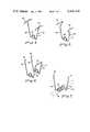
- FIG. 4is a perspective view of one modification of a support member in accordance with the present invention.
- FIG. 4shows the support member 55 in its relaxed position outside the envelope.
- the support member 55includes a coil 56 and first and second arms 57 and 58 having reverse bend portions adjoining the coil as in the embodiment illustrated in FIGS. 1--3.
- the free ends of the arms 57 and 58have portions 59 and 60 which extend parallel to the principal axis of the envelope along both directions from the arms 57 and 58, respectively.
- These portions 59 and 60bear against the envelope to provide elongated contact regions at the side walls at the entrance aperture of the envelope. Additional stability is thus provided for the support member virtually eliminating any tendency for twisting or shifting of the arms from the position they assume when in position in the envelope.
- the support member 65also includes a coil 66 and arms 67 and 68 which extend in substantially straight lines from reverse bend portions and lie in a single plane transverse to the principal axis of the envelope. Near their free ends the arms 67 and 68 are bent to provide two laterally extending portions 69 and 70 which function in a manner similar to the portions 59 and 60 of the support member 55 illustrated in FIG. 4 to provide additional stability.
- the support member 75 of FIG. 6is a still further modification in which essentially two support members are fabricated from a single length of flexible resilient wire.
- a section 76 extending parallel to the principal axis of the envelopeconnects corresponding arms 77 and 78 of the individual members.
- the free ends 79 and 80 of arms 81 and 82provide spaced-apart contact regions along one side of the envelope and the section 76 provides an elongated contact region along the other side. This arrangement thus provides very stable support for the support members themselves and also for the energy absorber.
- FIG. 7illustrates yet another modification of the support member in accordance with the present invention.
- the support member 90has a coil 91 of several turns which are spaced-apart along the direction of the principal axis of the envelope so as to grip the energy absorber 16, as shown in phantom, along a portion of its length.
- a first arm 92extends from one end of the coil and a second arm 93 extends from the opposite end of the coil.
- arms 92 and 93are spaced apart along the length of the envelope in separate transverse planes.
- Their free ends 94 and 95, respectively,bear against opposite sides of the envelope at contact regions which are spaced apart along the length of the envelope thus providing additional stability for the support member 90 and the energy absorber.
- Support members as illustratedare simple, inexpensive components for properly locating and supporting an energy absorber at the focal point within the envelope of an evacuated tube solar energy collector. They are tolerant of errors in manufacturing and permit ease of assembly. Their small diameter and the small surface areas of the contact with the energy absorber and with the envelope together with the lengths of their arms provide very poor conductive paths for leaking energy away from the energy absorber. In addition, the thin wire structure provides little interference to the insolation passing through the energy aperture and reflecting off the reflective surfaces onto the energy absorber.
Landscapes
- Engineering & Computer Science (AREA)
- Physics & Mathematics (AREA)
- Life Sciences & Earth Sciences (AREA)
- Sustainable Development (AREA)
- Sustainable Energy (AREA)
- Thermal Sciences (AREA)
- Chemical & Material Sciences (AREA)
- Combustion & Propulsion (AREA)
- Mechanical Engineering (AREA)
- General Engineering & Computer Science (AREA)
- Photovoltaic Devices (AREA)
Abstract
Description
Claims (3)
Priority Applications (1)
| Application Number | Priority Date | Filing Date | Title |
|---|---|---|---|
| US06/392,109US4440154A (en) | 1982-06-25 | 1982-06-25 | Solar energy collecting apparatus |
Applications Claiming Priority (1)
| Application Number | Priority Date | Filing Date | Title |
|---|---|---|---|
| US06/392,109US4440154A (en) | 1982-06-25 | 1982-06-25 | Solar energy collecting apparatus |
Publications (1)
| Publication Number | Publication Date |
|---|---|
| US4440154Atrue US4440154A (en) | 1984-04-03 |
Family
ID=23549283
Family Applications (1)
| Application Number | Title | Priority Date | Filing Date |
|---|---|---|---|
| US06/392,109Expired - Fee RelatedUS4440154A (en) | 1982-06-25 | 1982-06-25 | Solar energy collecting apparatus |
Country Status (1)
| Country | Link |
|---|---|
| US (1) | US4440154A (en) |
Cited By (32)
| Publication number | Priority date | Publication date | Assignee | Title |
|---|---|---|---|---|
| US4621634A (en)* | 1984-01-27 | 1986-11-11 | Trutek Research, Inc. | Anesthesia tubing connections |
| US5082027A (en)* | 1989-10-13 | 1992-01-21 | The Goodyear Tire & Rubber Company | Hose rotation restrainer |
| US5123591A (en)* | 1991-02-15 | 1992-06-23 | Reynolds William J | Radiator hose with internally mounted thermostat |
| US5265652A (en)* | 1992-05-29 | 1993-11-30 | Couple-Up, Inc. | Multiaxial fuel transfer pipe system |
| DE29808532U1 (en) | 1998-05-12 | 1998-10-01 | Schott-Rohrglas Gmbh, 95448 Bayreuth | Tube collector |
| DE19732481A1 (en)* | 1997-07-29 | 1999-02-18 | Deutsch Zentr Luft & Raumfahrt | Solar collector for solar-thermal power generation |
| DE19818773A1 (en)* | 1998-04-27 | 1999-11-04 | Peter Lutz | Solar collector as double-walled hollow body with inside insulating space |
| DE19821137A1 (en)* | 1998-05-12 | 1999-11-25 | Schott Rohrglas Gmbh | Solar energy tube collector |
| US5992468A (en)* | 1997-07-22 | 1999-11-30 | Camco International Inc. | Cable anchors |
| US6009906A (en)* | 1994-06-29 | 2000-01-04 | Salazar; Dennis R. | Method and apparatus for preventing pipe damage |
| US6119729A (en)* | 1998-09-14 | 2000-09-19 | Arise Technologies Corporation | Freeze protection apparatus for fluid transport passages |
| US6338364B1 (en) | 1999-09-01 | 2002-01-15 | Burke H. Mendenhall | Insert for freeze protecting water pipes |
| WO2003023292A1 (en)* | 2001-09-11 | 2003-03-20 | Manu Ghela | Solar collector pipe |
| US6604549B2 (en)* | 2001-09-27 | 2003-08-12 | Alcatel | Device for fixing a tubular element in an inaccessible cavity |
| US20040129267A1 (en)* | 2003-01-06 | 2004-07-08 | Davis Energy Group, Inc. | Molded polymer solar water heater |
| US20040163702A1 (en)* | 2002-08-07 | 2004-08-26 | Berry E. Wynn | Separated sanitary and storm sewer system |
| US20080029173A1 (en)* | 2006-08-07 | 2008-02-07 | Diperna Paul Mario | Variable flow reshapable flow restrictor apparatus and related methods |
| US20080121410A1 (en)* | 2006-06-20 | 2008-05-29 | Mccall Thomas Richard | Main duct with inner duct and method for producing the same |
| US20080178956A1 (en)* | 2007-01-26 | 2008-07-31 | Bruce Willingham | Fluid distribution apparatus and method of use thereof |
| US20090084581A1 (en)* | 2007-09-28 | 2009-04-02 | Vivant Medical, Inc. | Cable Stand-Off |
| WO2009039706A1 (en)* | 2007-09-25 | 2009-04-02 | Shenzhen Greenpower Solar Science & Technology Ltd. | An internal light-focusing glass vacuum solar heat-collecting pipe |
| US20100036327A1 (en)* | 2008-08-08 | 2010-02-11 | Tandem Diabetes Care, Inc. | Flow prevention, regulation, and safety devices and related methods |
| GB2469917A (en)* | 2009-04-27 | 2010-11-03 | Kingspan Holdings | Solar collector wire retaining clip |
| FR2959798A1 (en)* | 2010-05-05 | 2011-11-11 | Saint Gobain | Solar panel, particularly vacuum flat solar panel, comprises upper wall and lower wall, where upper spacer and lower spacer are firmly connected with absorption material in height of conduit pipe |
| US8287495B2 (en) | 2009-07-30 | 2012-10-16 | Tandem Diabetes Care, Inc. | Infusion pump system with disposable cartridge having pressure venting and pressure feedback |
| US8408421B2 (en) | 2008-09-16 | 2013-04-02 | Tandem Diabetes Care, Inc. | Flow regulating stopcocks and related methods |
| US8650937B2 (en) | 2008-09-19 | 2014-02-18 | Tandem Diabetes Care, Inc. | Solute concentration measurement device and related methods |
| EP2000748A3 (en)* | 2007-06-06 | 2014-04-02 | Herr Orhan Ustun | Collector element to generate heat from sun radiation and protective cover therefor |
| US8986253B2 (en) | 2008-01-25 | 2015-03-24 | Tandem Diabetes Care, Inc. | Two chamber pumps and related methods |
| US9962486B2 (en) | 2013-03-14 | 2018-05-08 | Tandem Diabetes Care, Inc. | System and method for detecting occlusions in an infusion pump |
| US20190017728A1 (en)* | 2016-01-08 | 2019-01-17 | Siemens Concentrated Solar Power Ltd. | Heat Receiver Tube With Metallic Sealing |
| US10258736B2 (en) | 2012-05-17 | 2019-04-16 | Tandem Diabetes Care, Inc. | Systems including vial adapter for fluid transfer |
Citations (18)
| Publication number | Priority date | Publication date | Assignee | Title |
|---|---|---|---|---|
| US1068650A (en)* | 1912-01-02 | 1913-07-29 | David A Harrison | Solar water-heater. |
| US2915089A (en)* | 1958-03-24 | 1959-12-01 | Ira Milton Jones | Resilient centering device for concentric cylindrical members |
| US3227153A (en)* | 1963-09-04 | 1966-01-04 | American Mach & Foundry | Solar collector |
| US3959056A (en)* | 1973-10-19 | 1976-05-25 | Caplan Harry W | Lightweight reflective panels for solar-thermal power plants and methods of forming such panels |
| US3983861A (en)* | 1975-08-21 | 1976-10-05 | Westman Manufacturing Company | Solar energy conversion device |
| US4067315A (en)* | 1975-10-24 | 1978-01-10 | Corning Glass Works | Solar heat pipe |
| DE2640060A1 (en)* | 1976-09-06 | 1978-03-16 | Hans Rueckstaedter | Glass vacuum solar energy collector tube - has horseshoe shaped tube reflector with internal black body |
| US4083360A (en)* | 1975-02-28 | 1978-04-11 | Battelle Memorial Institute | Device for collecting solar energy |
| US4091796A (en)* | 1976-08-16 | 1978-05-30 | Owens-Illinois, Inc. | Solar energy collection apparatus |
| US4120284A (en)* | 1977-04-14 | 1978-10-17 | Cotsworth John L | Clip for clinching a heat exchange conduit with a solar heat absorber |
| US4122832A (en)* | 1976-05-14 | 1978-10-31 | Ladislav Hirschsohn | Solar collector |
| US4133298A (en)* | 1975-09-26 | 1979-01-09 | Sanyo Electric Co., Ltd. | Solar heat collecting apparatus |
| US4149521A (en)* | 1975-07-24 | 1979-04-17 | Nasa | Solar energy collection system |
| US4175541A (en)* | 1977-11-14 | 1979-11-27 | Midgley Calvert H | Solar heating system |
| US4192292A (en)* | 1978-03-27 | 1980-03-11 | Root Edward J | Solar heating system |
| US4198955A (en)* | 1976-11-15 | 1980-04-22 | Canadian Sun Systems Ltd. | Solar energy collection system |
| US4215674A (en)* | 1978-05-18 | 1980-08-05 | Thermal Dynamics, Inc. | Radiant electromagnetic energy collector |
| US4307711A (en)* | 1980-02-25 | 1981-12-29 | Doundoulakis George J | Sun tracking solar energy collector system |
- 1982
- 1982-06-25USUS06/392,109patent/US4440154A/ennot_activeExpired - Fee Related
Patent Citations (18)
| Publication number | Priority date | Publication date | Assignee | Title |
|---|---|---|---|---|
| US1068650A (en)* | 1912-01-02 | 1913-07-29 | David A Harrison | Solar water-heater. |
| US2915089A (en)* | 1958-03-24 | 1959-12-01 | Ira Milton Jones | Resilient centering device for concentric cylindrical members |
| US3227153A (en)* | 1963-09-04 | 1966-01-04 | American Mach & Foundry | Solar collector |
| US3959056A (en)* | 1973-10-19 | 1976-05-25 | Caplan Harry W | Lightweight reflective panels for solar-thermal power plants and methods of forming such panels |
| US4083360A (en)* | 1975-02-28 | 1978-04-11 | Battelle Memorial Institute | Device for collecting solar energy |
| US4149521A (en)* | 1975-07-24 | 1979-04-17 | Nasa | Solar energy collection system |
| US3983861A (en)* | 1975-08-21 | 1976-10-05 | Westman Manufacturing Company | Solar energy conversion device |
| US4133298A (en)* | 1975-09-26 | 1979-01-09 | Sanyo Electric Co., Ltd. | Solar heat collecting apparatus |
| US4067315A (en)* | 1975-10-24 | 1978-01-10 | Corning Glass Works | Solar heat pipe |
| US4122832A (en)* | 1976-05-14 | 1978-10-31 | Ladislav Hirschsohn | Solar collector |
| US4091796A (en)* | 1976-08-16 | 1978-05-30 | Owens-Illinois, Inc. | Solar energy collection apparatus |
| DE2640060A1 (en)* | 1976-09-06 | 1978-03-16 | Hans Rueckstaedter | Glass vacuum solar energy collector tube - has horseshoe shaped tube reflector with internal black body |
| US4198955A (en)* | 1976-11-15 | 1980-04-22 | Canadian Sun Systems Ltd. | Solar energy collection system |
| US4120284A (en)* | 1977-04-14 | 1978-10-17 | Cotsworth John L | Clip for clinching a heat exchange conduit with a solar heat absorber |
| US4175541A (en)* | 1977-11-14 | 1979-11-27 | Midgley Calvert H | Solar heating system |
| US4192292A (en)* | 1978-03-27 | 1980-03-11 | Root Edward J | Solar heating system |
| US4215674A (en)* | 1978-05-18 | 1980-08-05 | Thermal Dynamics, Inc. | Radiant electromagnetic energy collector |
| US4307711A (en)* | 1980-02-25 | 1981-12-29 | Doundoulakis George J | Sun tracking solar energy collector system |
Cited By (50)
| Publication number | Priority date | Publication date | Assignee | Title |
|---|---|---|---|---|
| US4621634A (en)* | 1984-01-27 | 1986-11-11 | Trutek Research, Inc. | Anesthesia tubing connections |
| US5082027A (en)* | 1989-10-13 | 1992-01-21 | The Goodyear Tire & Rubber Company | Hose rotation restrainer |
| US5123591A (en)* | 1991-02-15 | 1992-06-23 | Reynolds William J | Radiator hose with internally mounted thermostat |
| US5265652A (en)* | 1992-05-29 | 1993-11-30 | Couple-Up, Inc. | Multiaxial fuel transfer pipe system |
| US6009906A (en)* | 1994-06-29 | 2000-01-04 | Salazar; Dennis R. | Method and apparatus for preventing pipe damage |
| US5992468A (en)* | 1997-07-22 | 1999-11-30 | Camco International Inc. | Cable anchors |
| DE19732481A1 (en)* | 1997-07-29 | 1999-02-18 | Deutsch Zentr Luft & Raumfahrt | Solar collector for solar-thermal power generation |
| DE19818773A1 (en)* | 1998-04-27 | 1999-11-04 | Peter Lutz | Solar collector as double-walled hollow body with inside insulating space |
| DE19821137B4 (en)* | 1998-05-12 | 2005-04-28 | Schott Ag | tube collector |
| DE19821137A1 (en)* | 1998-05-12 | 1999-11-25 | Schott Rohrglas Gmbh | Solar energy tube collector |
| DE29808532U1 (en) | 1998-05-12 | 1998-10-01 | Schott-Rohrglas Gmbh, 95448 Bayreuth | Tube collector |
| US6119729A (en)* | 1998-09-14 | 2000-09-19 | Arise Technologies Corporation | Freeze protection apparatus for fluid transport passages |
| US6338364B1 (en) | 1999-09-01 | 2002-01-15 | Burke H. Mendenhall | Insert for freeze protecting water pipes |
| WO2003023292A1 (en)* | 2001-09-11 | 2003-03-20 | Manu Ghela | Solar collector pipe |
| US6619283B2 (en)* | 2001-09-11 | 2003-09-16 | Manu Ghela | Solar collector pipe |
| CN100430670C (en)* | 2001-09-11 | 2008-11-05 | 马纳·格拉 | Solar energy collecting pipe |
| US6604549B2 (en)* | 2001-09-27 | 2003-08-12 | Alcatel | Device for fixing a tubular element in an inaccessible cavity |
| US7021338B2 (en)* | 2002-08-07 | 2006-04-04 | Berry Jr E Wynn | Separated sanitary and storm sewer system |
| US20040163702A1 (en)* | 2002-08-07 | 2004-08-26 | Berry E. Wynn | Separated sanitary and storm sewer system |
| US6814070B2 (en)* | 2003-01-06 | 2004-11-09 | Davis Energy Group, Inc. | Molded polymer solar water heater |
| US20040129267A1 (en)* | 2003-01-06 | 2004-07-08 | Davis Energy Group, Inc. | Molded polymer solar water heater |
| US20080121410A1 (en)* | 2006-06-20 | 2008-05-29 | Mccall Thomas Richard | Main duct with inner duct and method for producing the same |
| US20080029173A1 (en)* | 2006-08-07 | 2008-02-07 | Diperna Paul Mario | Variable flow reshapable flow restrictor apparatus and related methods |
| US20080178956A1 (en)* | 2007-01-26 | 2008-07-31 | Bruce Willingham | Fluid distribution apparatus and method of use thereof |
| EP2000748A3 (en)* | 2007-06-06 | 2014-04-02 | Herr Orhan Ustun | Collector element to generate heat from sun radiation and protective cover therefor |
| WO2009039706A1 (en)* | 2007-09-25 | 2009-04-02 | Shenzhen Greenpower Solar Science & Technology Ltd. | An internal light-focusing glass vacuum solar heat-collecting pipe |
| US20090084581A1 (en)* | 2007-09-28 | 2009-04-02 | Vivant Medical, Inc. | Cable Stand-Off |
| US8651146B2 (en)* | 2007-09-28 | 2014-02-18 | Covidien Lp | Cable stand-off |
| US8986253B2 (en) | 2008-01-25 | 2015-03-24 | Tandem Diabetes Care, Inc. | Two chamber pumps and related methods |
| US20100036327A1 (en)* | 2008-08-08 | 2010-02-11 | Tandem Diabetes Care, Inc. | Flow prevention, regulation, and safety devices and related methods |
| US8408421B2 (en) | 2008-09-16 | 2013-04-02 | Tandem Diabetes Care, Inc. | Flow regulating stopcocks and related methods |
| US8448824B2 (en) | 2008-09-16 | 2013-05-28 | Tandem Diabetes Care, Inc. | Slideable flow metering devices and related methods |
| US8650937B2 (en) | 2008-09-19 | 2014-02-18 | Tandem Diabetes Care, Inc. | Solute concentration measurement device and related methods |
| GB2469917A (en)* | 2009-04-27 | 2010-11-03 | Kingspan Holdings | Solar collector wire retaining clip |
| WO2010125549A3 (en)* | 2009-04-27 | 2011-02-24 | Kingspan Holdings (Irl) Limited | Solar collector |
| US20120042872A1 (en)* | 2009-04-27 | 2012-02-23 | Mcentee Paul Thomas | Solar collector |
| US8776782B2 (en)* | 2009-04-27 | 2014-07-15 | Kingspan Holdings (Irl) Limited | Solar collector |
| US8758323B2 (en) | 2009-07-30 | 2014-06-24 | Tandem Diabetes Care, Inc. | Infusion pump system with disposable cartridge having pressure venting and pressure feedback |
| US8298184B2 (en) | 2009-07-30 | 2012-10-30 | Tandem Diabetes Care, Inc. | Infusion pump system with disposable cartridge having pressure venting and pressure feedback |
| US8287495B2 (en) | 2009-07-30 | 2012-10-16 | Tandem Diabetes Care, Inc. | Infusion pump system with disposable cartridge having pressure venting and pressure feedback |
| US8926561B2 (en) | 2009-07-30 | 2015-01-06 | Tandem Diabetes Care, Inc. | Infusion pump system with disposable cartridge having pressure venting and pressure feedback |
| US9211377B2 (en) | 2009-07-30 | 2015-12-15 | Tandem Diabetes Care, Inc. | Infusion pump system with disposable cartridge having pressure venting and pressure feedback |
| US11135362B2 (en) | 2009-07-30 | 2021-10-05 | Tandem Diabetes Care, Inc. | Infusion pump systems and methods |
| US11285263B2 (en) | 2009-07-30 | 2022-03-29 | Tandem Diabetes Care, Inc. | Infusion pump systems and methods |
| US12042627B2 (en) | 2009-07-30 | 2024-07-23 | Tandem Diabetes Care, Inc. | Infusion pump systems and methods |
| US12144964B2 (en) | 2009-07-30 | 2024-11-19 | Tandem Diabetes Care, Inc | Infusion pump system with disposable cartridge having pressure venting and pressure feedback |
| FR2959798A1 (en)* | 2010-05-05 | 2011-11-11 | Saint Gobain | Solar panel, particularly vacuum flat solar panel, comprises upper wall and lower wall, where upper spacer and lower spacer are firmly connected with absorption material in height of conduit pipe |
| US10258736B2 (en) | 2012-05-17 | 2019-04-16 | Tandem Diabetes Care, Inc. | Systems including vial adapter for fluid transfer |
| US9962486B2 (en) | 2013-03-14 | 2018-05-08 | Tandem Diabetes Care, Inc. | System and method for detecting occlusions in an infusion pump |
| US20190017728A1 (en)* | 2016-01-08 | 2019-01-17 | Siemens Concentrated Solar Power Ltd. | Heat Receiver Tube With Metallic Sealing |
Similar Documents
| Publication | Publication Date | Title |
|---|---|---|
| US4440154A (en) | Solar energy collecting apparatus | |
| US4205655A (en) | Solar collector | |
| CA1065716A (en) | Solar collector comprising an elongate absorber in an evacuated transparent tube | |
| CN100414213C (en) | Radiant heat shield for solar energy system | |
| US4080954A (en) | Solar collector apparatus | |
| US8511298B2 (en) | Reflective solar energy collection system | |
| US4091796A (en) | Solar energy collection apparatus | |
| US4356815A (en) | Solar energy collector having an absorber element of coated foil | |
| JP3880621B2 (en) | Non-imaging type solar concentrator | |
| US4649903A (en) | Solar heat collector | |
| US4307709A (en) | Internal absorber solar collector | |
| US4377155A (en) | Solar energy collector assembly | |
| US5967140A (en) | Nonimaging solar collector | |
| US4426996A (en) | Solar collector apparatus | |
| CN101111729B (en) | A reflector and a receiver for a solar energy collection system | |
| WO2004090437A1 (en) | Solar collector of the cpc type | |
| RU2800202C1 (en) | Solar collector with solar radiation concentrator | |
| KR100406835B1 (en) | Structures design of reflector and absorber of solar energy concentrators | |
| JPS5919243Y2 (en) | solar collector | |
| JPH0355735B2 (en) | ||
| JPS5919241Y2 (en) | solar collector heat collector | |
| JPS5941483Y2 (en) | solar collector | |
| JPS6012993Y2 (en) | solar collector | |
| CA1102194A (en) | Solar energy collection apparatus | |
| JPS6028906Y2 (en) | solar heat collector |
Legal Events
| Date | Code | Title | Description |
|---|---|---|---|
| AS | Assignment | Owner name:GTE LABORATORIES INCORPORATED, A DE CORP Free format text:ASSIGNMENT OF ASSIGNORS INTEREST.;ASSIGNOR:BELLOWS, ALFRED H.;REEL/FRAME:004017/0117 Effective date:19820622 Owner name:GTE LABORATORIES INCORPORATED, MASSACHUSETTS Free format text:ASSIGNMENT OF ASSIGNORS INTEREST;ASSIGNOR:BELLOWS, ALFRED H.;REEL/FRAME:004017/0117 Effective date:19820622 | |
| MAFP | Maintenance fee payment | Free format text:PAYMENT OF MAINTENANCE FEE, 4TH YEAR, PL 96-517 (ORIGINAL EVENT CODE: M170); ENTITY STATUS OF PATENT OWNER: LARGE ENTITY Year of fee payment:4 | |
| FEPP | Fee payment procedure | Free format text:PAYOR NUMBER ASSIGNED (ORIGINAL EVENT CODE: ASPN); ENTITY STATUS OF PATENT OWNER: LARGE ENTITY | |
| MAFP | Maintenance fee payment | Free format text:PAYMENT OF MAINTENANCE FEE, 8TH YEAR, PL 96-517 (ORIGINAL EVENT CODE: M171); ENTITY STATUS OF PATENT OWNER: LARGE ENTITY Year of fee payment:8 | |
| FEPP | Fee payment procedure | Free format text:PAYOR NUMBER ASSIGNED (ORIGINAL EVENT CODE: ASPN); ENTITY STATUS OF PATENT OWNER: LARGE ENTITY Free format text:PAYER NUMBER DE-ASSIGNED (ORIGINAL EVENT CODE: RMPN); ENTITY STATUS OF PATENT OWNER: LARGE ENTITY | |
| FEPP | Fee payment procedure | Free format text:MAINTENANCE FEE REMINDER MAILED (ORIGINAL EVENT CODE: REM.); ENTITY STATUS OF PATENT OWNER: LARGE ENTITY | |
| LAPS | Lapse for failure to pay maintenance fees | ||
| FP | Lapsed due to failure to pay maintenance fee | Effective date:19960403 | |
| STCH | Information on status: patent discontinuation | Free format text:PATENT EXPIRED DUE TO NONPAYMENT OF MAINTENANCE FEES UNDER 37 CFR 1.362 |