US4439924A - Rotary hand knife - Google Patents
Rotary hand knifeDownload PDFInfo
- Publication number
- US4439924A US4439924AUS06/318,386US31838681AUS4439924AUS 4439924 AUS4439924 AUS 4439924AUS 31838681 AUS31838681 AUS 31838681AUS 4439924 AUS4439924 AUS 4439924A
- Authority
- US
- United States
- Prior art keywords
- blade
- housing
- face
- handle
- radial face
- Prior art date
- Legal status (The legal status is an assumption and is not a legal conclusion. Google has not performed a legal analysis and makes no representation as to the accuracy of the status listed.)
- Expired - Lifetime
Links
Images


Classifications
- B—PERFORMING OPERATIONS; TRANSPORTING
- B26—HAND CUTTING TOOLS; CUTTING; SEVERING
- B26B—HAND-HELD CUTTING TOOLS NOT OTHERWISE PROVIDED FOR
- B26B25/00—Hand cutting tools involving disc blades, e.g. motor-driven
- B26B25/002—Motor-driven knives with a rotating annular blade
Definitions
- This inventionrelates to an improved hand knife of the type used for trimming meat with a rotary driven ring-like blade, and to an improved blade housing, blade and mechanism for retaining the blade.
- Rotary knives with ring-like power-driven blades of the type pertaining to this inventionare exemplified by such structures as shown in U.S. Pat. Nos. Re. 25,947 and 4,175,321.
- Such kniveshave a rotary ring-like or annular blade, generally frusto-conical in form, sharpened at one axial end and incorporating gear teeth to form a ring gear portion at the other axial end.
- the ring gear portionis located and guided by a ring-like housing that is secured to a handle.
- the bladeis driven by a pinion carried by the handle.
- an arm-like sector portionextends around one side of the blade and housing, to support a blade-retaining shoe held in place by several securing screws and located by stop screws.
- the shoeis clamped directly against the blade, squeezing it slightly against the housing to retain it.
- the operations required for the release or removal and subsequent readjustment of the blade-retaining shoe for blade changingdiscourage blade substitution during use of the knife, such as during a work shift; yet, cutting efficiency depends upon use of a sharp blade. Also, dull blades result in waste product because deeper cuts are required to get the blade started into the meat.
- the housingwas not constructed to restrain movement of the blade in an axial direction away from the housing, reliance being instead upon the retaining shoe adjacent the handle.
- the knifewas pushed against a product or pulled substantially parallel with the surface of a product, this was satisfactory, but on occasions the knife is urged in a direction away from the surface during cutting, in which case the part of the blade beyond the retaining shoe tends to be pulled from the housing. This may result in loss of control of the depth of the cut as well as mechanical difficulties.
- the present inventionprovides an improved rotary knife having a new and improved blade housing, blade, and blade-retaining shoe construction that overcome the above disadvantages and permit convenient removal and replacement of the blade without removal of shoe retaining screws, or the shoe itself, or other parts of the knife from the handle, and additionally retain the blade in an improved manner.
- the knife of the present inventioncomprises a handle, a ring-like blade housing removably attached to the handle, a frusto-conical ring blade located and guided for rotation by the housing, and a blade-retaining plate adjustably and removably held against the housing and blade.
- the bladehas gear teeth that form a ring gear portion adjacent the housing, a beveled or frusto-conical outer periphery about the ring gear portion against which blade-retaining surfaces of the knife act, and a circular cutting edge that extends forwardly from the housing.
- the bladeis driven by a pinion in the handle, engaged with the ring gear portion. In use, a portion of the blade and housing is moved through a work body and cut product passes through the central open part of the blade and housing.
- the particular embodiment disclosed hereinis used primarily to trim fat or skin from the surface of meat.
- the improved knife constructionhas a circular blade housing with a partial peripheral flange that captures a circumferential portion of the blade farthest from the handle to restrain axial movement of the blade.
- the flangeextends circumferentially a distance no greater than 180 angular degrees about the blade.
- the remainder of the housingprovides a flat annular support surface against which the ring gear portion of the blade slides during rotation.
- the flanged part of the housinghas a thin profile that forms a partial frusto-conical extension of the blade at the ring gear portion and is very little thicker than the blade, to pass in use with minimum resistance between the product and a slice being cut by the knife.
- the knife handlehas an arcuate end with an arm-like sector portion extending from one side about a portion of the housing.
- a plate-like blade-retaining shoeextends along the arcuate end of the handle and is pivotably attached at one end to the end of the sector portion.
- An inside arcuate beveled edge of the shoeengages the outer beveled surface of the blade, and a flat face surface of the shoe is positioned against the unflanged portion of the housing adjacent to the knife handle.
- the beveled edgeretains the blade within the housing flange and against the unflanged part of the housing.
- a securing member carried with the handlecooperates with the shoe to hold it against the housing while allowing pivotal movement of the shoe in the plane of the shoe for adjustment toward or away from the blade periphery.
- the securing memberalso readily releases the shoe to allow the shoe to swing about its pivotal attachment to a position away from the housing, allowing the blade to be moved toward the handle, out of captured relationship with the peripheral housing flange, for removal.
- An adjustable abutment carried by the handleengages an outer edge of the shoe when the shoe is in blade-retaining position. Through hand-adjustment, the abutment can be moved to pivot the shoe about its attached end to locate and retain the inside beveled edge of the shoe against the outer frusto-conical peripheral surface of the ring gear part of the blade, with adequate frictional contact to hold the blade in operating position relative to the housing, yet sufficiently free to rotate.
- the present inventionprovides a hand knife for cutting meat and the like comprising a handle, a ring-like blade housing at one end of the handle, a continuous ring blade supported and guided for rotation by said housing, a blade retainer secured to the handle and located to engage an outer surface of the blade, and means to locate the retainer against the blade, said housing having an annular radial face and said blade having one axial end that is located and guided by said face and a portion that extends from the face and terminates in a circular cutting edge, and said housing having an arcuate wall that extends axially from the radial face in the direction said blade portion extends and peripherally about said radial face, said arcuate wall including a lip directed radially inward of the housing, that extends no more than 180 angular degrees and located peripherally remote from the blade retainer, and that restrains axial movement of the blade relative to said radial face.
- FIG. 1is a front elevational view of the hand knife embodying the present invention, with parts broken away;
- FIG. 2is a longitudinal sectional view of the hand knife of FIG. 1 taken along the line 2--2;
- FIG. 3is a perspective view of the hand knife of FIG. 1;
- FIG. 4is a partial sectional view taken along the line 4--4 of FIG. 1;
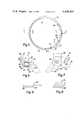
- FIG. 5is a plan view of a housing of the hand knife of FIG. 1;
- FIG. 6is a partial sectional view taken along 6--6 of FIG. 5;
- FIG. 7is a partial sectional view taken along the line 7--7 of FIG. 5;
- FIG. 8is a partial sectional view taken along the line 8--8 of FIG. 5;
- FIG. 9is a partial side elevational view taken approximately from the plane 9--9 of FIG. 5;
- FIG. 10is a partial sectional view taken along the line 10--10 of FIG. 1.
- a hand knife 20 embodying the inventionis best shown in FIGS. 1-3 and comprises a hand piece 22 having a tubular handle 24 and an arcuate end 26 including arm-like sector portions 26a, 26b (portion 26a being longer in the preferred embodiment); a ring-like housing 30 secured to the sector portions of the hand piece by two screws 32; a ring-like annular blade 34 rotatable relative to the housing; and a retaining shoe 36 connected to the hand piece by a pivot connection 38 and secured in a blade-retaining position against a front face 39 of the hand piece by a headed screw 40 in the sector portion 26b.
- the blade 34is located and guided in rotation by both the housing 30 and the shoe 36.
- Both the housing 30 and blade 34are of short axial length relative to their diameters.
- the bladeis frusto-conical in shape, with gear teeth 42 at the axial end of larger diameter, which is received against the housing, and has a cutting edge 44 formed at the other and smaller axial end, which extends axially from the general plane of the housing 30 and forms the front of the knife 20.
- a power driven pinion gear 46 in the hand piece 22engages the gear teeth 42 and rotates the blade relative to the housing.
- the pinionis driven by a rotated cable 48 powered by an external electric motor (not shown).
- the pinioncan be powered by an air driven motor and gearing within the tubular handle part 24.
- the blade 34is rotated at a relatively high speed and the face of the knife (i.e., the cutting edge 44) is placed against a product, and the knife is drawn along the product in the direction of the handle, toward the operator, pulling part of the blade and housing that are remote from the handle through the product.
- a resulting slice of the productpasses through the central opening 50 of the housing and blade.
- the construction and shape of the blade and housingfacilitate cutting thin layers from the product; for example, patches of skin or thin layers of fat from the surface of a meat product.
- the hand piece 22is a metal casting and the tubular handle part 24 has a central recess 52.
- a flanged tubular bushing 54is located at the arcuate end of the hand piece.
- the pinion gear 46is rotatably supported in the bushing and received in a recess 56 in the arcuate end of the hand piece.
- a plastic cover 58is secured to the hand piece by screws 60 to cover the pinion gear 46.
- a flexible cable sheath 62is received in the tubular handle part 24 and secured within the handle by a screw 64.
- a central cable 66is rotatably housed by the sheath 62 and is secured to the pinion gear 46 to drive the gear when the cable is rotated by an electric motor (not shown).
- a grease reservoir 68 on the hand piececommunicates with the pinion to provide lubrication.
- the pivot conenction 38 at the end of the sector portion 26ais comprised of an internally threaded bushing 70 secured to one end of the retaining shoe 36, and a thumb screw 72.
- the bushingextends through a hole 74 through the sector and the thumb screw 72 that is received in the bushing has a shoulder 75 that acts against the sector portion 26a on the opposite side from the retaining shoe so the screw draws the shoe against the hand piece.
- Loosening of the thumb screw 72allows the retaining shoe to be pivoted about the axis of the screw and also allows the shoe to move away from the front face 39 of the hand piece.
- the securing screw 40 in the front face of the sector portion 26bsecures the distal end of the shoe 36 by cooperating with a keyhole slot 78 in the shoe.
- the slotis elongated in a direction that allows the shoe to pivot a short distance toward and away from the blade while the screw is received in the slot.
- a hand wheel 80 with a shaft 81is received in a threaded aperture 82 in the sector portion 26b.
- the hand wheelacts as an abutment to the shoe 36 for adjusting and maintaining the position of the shoe relative to the blade.
- a spring 83 surrounding the shaft 81 and acting against the hand wheel and sector portion 26bholds the hand wheel in adjusted position.
- the blade housing 30is circular in shape, as best shown in FIG. 5, and has varying cross sectional shapes at different portions, as illustrated by FIGS. 6 to 9.
- the heads of the two securing screws 32fit against flats 84 in the inside periphery of the housing, the screws being received in threaded apertures in the arcuate end 26 of the hand piece.
- the housinghas a cut away portion 86 between the flats 84 to receive the pinion gear 46, allowing it to cooperate with the gear teeth of the blade 34.
- the housinghas a radial face 88 at the front, against which the blade 34 is located and against which it slides in rotation.
- the radial facevaries in width circumferentially of the housing, being wider in that portion of the housing adjacent the arcuate end 26 of the hand piece, and being thinner along that part of the housing that extends beyond the arcuate end 26 of the hand piece. This can be appreciated by comparing the narrow width of the housing shown in FIG. 6 with the greater widths shown in FIGS. 7 and 8.
- a peripheral flange 90extends about the radial face 88 in that portion of the housing that extends beyond the arcuate end 26 (i.e., beyond the sector portions 26a, 26b).
- the circumferential extent of the peripheral flangeis no more than 180° about the housing.
- the flangeincludes a cylindrical inside surface portion 91 and a frusto-conical inside surface 92 of an inturned lip 93.
- the outer surface 94 of the flangeis also frusto-conical and is parallel with a frusto-conical back surface 95 of the housing (FIG. 6).
- the two parallel frusto-conical outside surfaces 94, 95are joined at the outside periphery of the housing by a cylindrical surface 96 and a very thin flat annular surface 97 that avoids a sharp edge.
- Ends 99, 100 of the peripheral flangeare shown in FIGS. 3, 5 and 9, and in the preferred embodiment are substantially diametrically opposite each other and directly adjacent the ends of sector portions 26a, 26b.
- the blade 34is located with the gear teeth portion 42 against the radial face 88 of the housing, and in part captured by the peripheral flange 90.
- the outer peripheral surface of the bladehas a frusto-conical portion 102 about the gear teeth portion 42, which is the thickest portion of the blade.
- the frusto-conical portion 102ends in a radial flange surface 104, where the thickness of the blade narrows from that of the teeth portion to a thinner part 105 that terminates in the cutting edge 44.
- the frusto-conical portion 102rides against the inside surface 92 of the inturned lip 93, while the gear teeth portion 42 rides against the radial face 88 and the cylindrical surface 96 of the housing.
- the retaining shoe 36rests against the radial face 88 of the housing and also against the outer frusto-conical surface 102 of the blade.
- the distance between the frusto-conical surfaces 94 and 95 of the housingis not substantially greater than the thickness of the gear teeth portion 42 of the blade, and those housing surfaces extend at substantially the same angle as the blade.
- the flanged portion of the housingextends from the blade at the gear teeth end in a way that does not interfere with the passage of the blade through the product being sliced, due to an absence of any greatly increased thickness or peripherally extending housing surfaces of significant width.
- the retaining shoe 36is in the form of an arcuate plate substantially congruent with and overlying the front face 39 at the arcuate end 26 of the hand piece 22.
- An inner edge 110 of the shoeis beveled to correspond with the frusto-conical peripheral surface portion 102 of the blade and is shaped to the same radius of curvature so it bears against that blade portion when positioned with the center of curvature coincident with that of the blade center.
- the keyhole slot 78receives the headed securing screw 40.
- An enlarged portion 78a of the keyhole slotis larger than the head of the securing screw 40, and a narrower portion 78b receives the shank of the screw 40 when the shoe is located to contact the blade.
- the head of the screwprevents movement of the shoe away from the front face 39 of the handpiece.
- Loosening of the thumb screw 74 at pivot 38permits movement of the shoe toward and away from the face of the hand piece to allow movement of the shoe over the head of the securing screw 40 and then allows the shoe to pivot away from the arcuate end 26, as shown in FIG. 3.
- the securing screw 40is adjustable in a threaded bore 112 in the sector portion 26b.
- a set screw 114 in the threaded bore adjacent the opposite face of the hand piecelocates the securing screw and establishes the distance between the front face 39 of the hand piece and the set screw head, so the shoe is closely received in the gap between the front face and the head of the screw 40.
- An outer edge 116 of the shoe 36has a lobe 118 providing a wider part of the shoe that extends beyond the sector portion 26b and is engaged by the hand wheel 80.
- the hand wheelis rotated to back it away from the shoe, allowing the shoe to be pivoted about the pivot assembly 38, bringing the enlarged portion of the slot into alignment with the screw head.
- the thumb screw 72is then loosened and the shoe is moved away from the front face of the hand piece, beyond the screw, and is then pivoted away from the blade to a position shown in FIG. 3.
- the bladecan then be moved out of the peripheral flange 90, toward the handle part 24 and lifted away from the housing and hand piece. A new blade is inserted by reversing the procedure. In this way, an operator can readily change blades without the use of tools or complex adjustments and frequent blade change is thereby encouraged and greater cutting efficiency achieved.
Landscapes
- Life Sciences & Earth Sciences (AREA)
- Forests & Forestry (AREA)
- Engineering & Computer Science (AREA)
- Mechanical Engineering (AREA)
- Knives (AREA)
- Processing Of Meat And Fish (AREA)
- Details Of Cutting Devices (AREA)
Abstract
Description
Claims (19)
Priority Applications (13)
| Application Number | Priority Date | Filing Date | Title |
|---|---|---|---|
| US06/318,386US4439924A (en) | 1981-11-05 | 1981-11-05 | Rotary hand knife |
| AU88926/82AAU539551B2 (en) | 1981-11-05 | 1982-09-30 | Rotary blade knife |
| BR8205977ABR8205977A (en) | 1981-11-05 | 1982-10-13 | MANUAL KNIFE FOR CUTTING MEAT AND SIMILARS |
| FI823511AFI78006C (en) | 1981-11-05 | 1982-10-14 | ROTERANDE HANDKNIV. |
| JP57180553AJPS58127687A (en) | 1981-11-05 | 1982-10-14 | Hand knife |
| AR290969AAR229709A1 (en) | 1981-11-05 | 1982-10-14 | ROTARY HAND KNIFE |
| DK455082ADK455082A (en) | 1981-11-05 | 1982-10-14 | HAND-OPERATED ROUND KNIFE FOR CUTTING OFF MEAT |
| SU823511954ASU1463118A3 (en) | 1981-11-05 | 1982-11-02 | Hand knife for cutting meat raw material |
| CA000414728ACA1200088A (en) | 1981-11-05 | 1982-11-03 | Rotary hand knife |
| AT82305867TATE34534T1 (en) | 1981-11-05 | 1982-11-04 | HAND KNIFE WITH ROTATIONAL RING-SHAPED BLADE. |
| DE8282305867TDE3278534D1 (en) | 1981-11-05 | 1982-11-04 | Handknife with rotating annular blade |
| EP82305867AEP0079203B1 (en) | 1981-11-05 | 1982-11-04 | Handknife with rotating annular blade |
| US06/485,738US4492027A (en) | 1981-11-05 | 1983-04-18 | Rotary hand knife |
Applications Claiming Priority (1)
| Application Number | Priority Date | Filing Date | Title |
|---|---|---|---|
| US06/318,386US4439924A (en) | 1981-11-05 | 1981-11-05 | Rotary hand knife |
Related Child Applications (1)
| Application Number | Title | Priority Date | Filing Date |
|---|---|---|---|
| US06/485,738Continuation-In-PartUS4492027A (en) | 1981-11-05 | 1983-04-18 | Rotary hand knife |
Publications (1)
| Publication Number | Publication Date |
|---|---|
| US4439924Atrue US4439924A (en) | 1984-04-03 |
Family
ID=23237963
Family Applications (2)
| Application Number | Title | Priority Date | Filing Date |
|---|---|---|---|
| US06/318,386Expired - LifetimeUS4439924A (en) | 1981-11-05 | 1981-11-05 | Rotary hand knife |
| US06/485,738Expired - LifetimeUS4492027A (en) | 1981-11-05 | 1983-04-18 | Rotary hand knife |
Family Applications After (1)
| Application Number | Title | Priority Date | Filing Date |
|---|---|---|---|
| US06/485,738Expired - LifetimeUS4492027A (en) | 1981-11-05 | 1983-04-18 | Rotary hand knife |
Country Status (12)
| Country | Link |
|---|---|
| US (2) | US4439924A (en) |
| EP (1) | EP0079203B1 (en) |
| JP (1) | JPS58127687A (en) |
| AR (1) | AR229709A1 (en) |
| AT (1) | ATE34534T1 (en) |
| AU (1) | AU539551B2 (en) |
| BR (1) | BR8205977A (en) |
| CA (1) | CA1200088A (en) |
| DE (1) | DE3278534D1 (en) |
| DK (1) | DK455082A (en) |
| FI (1) | FI78006C (en) |
| SU (1) | SU1463118A3 (en) |
Cited By (43)
| Publication number | Priority date | Publication date | Assignee | Title |
|---|---|---|---|---|
| US4516323A (en)* | 1983-04-18 | 1985-05-14 | Bettcher Industries, Inc. | Rotary hand knife and parts therefor |
| US4575938A (en)* | 1984-07-12 | 1986-03-18 | Mccullough Timothy J | Meat trimming knife |
| US4637140A (en)* | 1981-12-14 | 1987-01-20 | Bettcher Industries, Inc. | Boning and trimming knife |
| US4854046A (en)* | 1987-10-07 | 1989-08-08 | Bettcher Industries, Inc. | Rotary hand trimming knife |
| US4858321A (en)* | 1988-03-04 | 1989-08-22 | Mccullough Timothy J | Slotted depth gauge plate |
| US5230154A (en)* | 1990-09-28 | 1993-07-27 | Bettcher Industries, Inc. | Modular power-driven rotary knife, improved handle and method |
| EP0689905A1 (en) | 1994-06-30 | 1996-01-03 | Bettcher Industries, Inc. | Rotary knife and slicing gauge |
| US5664332A (en)* | 1996-02-14 | 1997-09-09 | Bettcher Industries, Inc. | Hand knife with cover |
| US5761817A (en)* | 1996-10-17 | 1998-06-09 | Bettcher Industries, Inc. | Rotary hand knife |
| EP1418028A1 (en)* | 2002-11-06 | 2004-05-12 | LGR Equipment di Graziano Roncaglia | Tool for rotary knives |
| WO2004043655A1 (en) | 2002-11-07 | 2004-05-27 | Bettcher Industries, Inc | Rotary knife having vacuum attachment |
| US6769184B1 (en)* | 1998-07-22 | 2004-08-03 | Bettcher Industries, Inc. | Low friction rotary knife |
| US20060037200A1 (en)* | 2004-08-19 | 2006-02-23 | Bettcher Industries, Inc. | Rotary knife with improved drive transmission |
| US20100101097A1 (en)* | 2007-03-08 | 2010-04-29 | Forschungs-Und Entwicklungsgesellschaft Fur Technische Produkte Gmbh & Co., Kg | Cutting Knife, in Particular for Cutting Food |
| US20110185580A1 (en)* | 2010-02-01 | 2011-08-04 | Bettcher Industries, Inc. | Large diameter notched blade and blade housing for power operated rotary knife |
| WO2013062973A1 (en)* | 2011-10-27 | 2013-05-02 | Hantover, Inc. | Rotary knife with mechanism for controlling blade housing |
| US20140074120A1 (en)* | 2012-09-07 | 2014-03-13 | Exsurco Medical, Inc. | Power Operated Dermatome WIth Shielded Rotary Knife Blade |
| US8695222B2 (en) | 2011-07-25 | 2014-04-15 | Bettcher Industries, Inc. | Power operated rotary knife |
| US8726524B2 (en) | 2011-07-25 | 2014-05-20 | Bettcher Industries, Inc. | Power operated rotary knife |
| US8739416B2 (en) | 2011-07-25 | 2014-06-03 | Bettcher Industries, Inc. | Power operated rotary knife |
| US8745881B2 (en) | 2011-07-25 | 2014-06-10 | Bettcher Industries, Inc. | Power operated rotary knife |
| US8756819B2 (en) | 2010-04-12 | 2014-06-24 | Bettcher Industries, Inc. | Power operated rotary knife with disposable blade support assembly |
| US8806761B2 (en) | 2011-07-25 | 2014-08-19 | Bettcher Industries, Inc. | Power operated rotary knife |
| US20140259690A1 (en)* | 2013-03-14 | 2014-09-18 | Bettcher Industries, Inc | Moveable lubrication assembly for power operated rotary knife |
| US8950076B2 (en) | 2011-07-25 | 2015-02-10 | Bettcher Industries, Inc. | Power operated rotary knife |
| US9186171B2 (en) | 2012-09-07 | 2015-11-17 | Exsurco Medical, Inc. | Power operated debridement tool with disk knife blade |
| US9452541B2 (en) | 2014-07-29 | 2016-09-27 | Bettcher Industries, Inc. | Power operated rotary knife with vacuum attachment assembly |
| US9579810B2 (en) | 2014-07-29 | 2017-02-28 | Bettcher Industries, Inc. | Power operated rotary knife with vacuum attachment assembly |
| WO2017156750A1 (en)* | 2016-03-17 | 2017-09-21 | 刘秋平 | Handheld annular cutting blade |
| US9833919B2 (en) | 2015-10-02 | 2017-12-05 | Bettcher Industries, Inc. | Power operated rotary knife |
| US10022146B2 (en) | 2015-05-29 | 2018-07-17 | Exsurco Medical, Inc. | Power operated rotary excision tool |
| US10040211B2 (en) | 2016-12-09 | 2018-08-07 | Bettcher Industries, Inc. | Power operated rotary knife |
| US10124500B2 (en) | 2016-12-09 | 2018-11-13 | Bettcher Industries, Inc. | Cam-actuated split blade housing for power operated rotary knife |
| US10123544B2 (en)* | 2015-03-24 | 2018-11-13 | Teknologisk Institut | Tool for removal of meat pieces such as tenderloin from a carcass |
| US20190111581A1 (en)* | 2017-10-16 | 2019-04-18 | Hantover, Inc. | Rotary knife providing material removal via suction |
| US10343296B2 (en) | 2015-07-25 | 2019-07-09 | Bettcher Industries, Inc. | Power operated rotary knife with notched rotary knife blade and trim guide |
| US10471614B2 (en) | 2016-12-09 | 2019-11-12 | Bettcher Industries, Inc. | Cam-actuated split blade housing for power operated rotary knife |
| US10537356B2 (en) | 2014-06-16 | 2020-01-21 | Exsurco Medical, Inc. | Power operated rotary excision tool |
| USD907205S1 (en) | 2012-09-07 | 2021-01-05 | Exsurco Medical, Inc. | Power operated rotary excision tool |
| USD912489S1 (en) | 2019-06-13 | 2021-03-09 | Bettcher Industries, Inc. | Housing for a power operated rotary knife |
| US11077571B2 (en) | 2019-10-02 | 2021-08-03 | Bettcher Industries, Inc. | Split blade housing with expansion sleeve assembly for power operated rotary knife |
| USD973115S1 (en) | 2018-01-26 | 2022-12-20 | Bettcher Industries, Inc. | Annular blade |
| USD1094052S1 (en) | 2016-12-09 | 2025-09-23 | Bettcher Industries, Inc. | Annular blade |
Families Citing this family (9)
| Publication number | Priority date | Publication date | Assignee | Title |
|---|---|---|---|---|
| DE3812336C1 (en)* | 1988-04-14 | 1989-08-24 | Effem Gmbh, 2810 Verden, De | |
| AUPO592397A0 (en)* | 1997-03-27 | 1997-04-24 | Parke, Terrence James | A rotary cutting device |
| US6694649B2 (en) | 2001-11-07 | 2004-02-24 | Bettcher Industries, Inc. | Motor driven knife including depth limiting device |
| US7722448B2 (en)* | 2006-08-16 | 2010-05-25 | Jarvis Products Corporation | Dehider with governor and strengthened blade |
| US20070283573A1 (en)* | 2006-06-09 | 2007-12-13 | Hantover, Inc. | Rotary knife with blade bushing |
| DE202010008081U1 (en)* | 2010-07-15 | 2010-10-21 | Freund Maschinenfabrik Gmbh & Co. Kg | Knife quick-change system for meat trimmers |
| US9592076B2 (en)* | 2012-09-07 | 2017-03-14 | Exsurco Medical, Inc. | Power operated dermatome with rotary knife blade |
| RU2770318C1 (en)* | 2017-11-27 | 2022-04-15 | Беттчер Индастрис, Инк. | Cam-driven blade housing with slot for a driven rotating knife |
| WO2025160473A1 (en)* | 2024-01-26 | 2025-07-31 | Hantover, Inc. | Rotary knife deflector for directing trimmings |
Citations (11)
| Publication number | Priority date | Publication date | Assignee | Title |
|---|---|---|---|---|
| US25947A (en)* | 1859-11-01 | And henry still | ||
| USRE25947E (en) | 1965-12-14 | Trimming and slicing device | ||
| US3688403A (en)* | 1970-10-21 | 1972-09-05 | Bettcher Industries | Knife |
| US3852882A (en)* | 1974-01-28 | 1974-12-10 | Bettcher Industries | Air driven boning and trimming knives |
| US4166317A (en)* | 1977-10-17 | 1979-09-04 | Bettcher Industries, Inc. | Trimming knife |
| US4170063A (en)* | 1978-07-17 | 1979-10-09 | Bettcher Industries, Inc. | Knife with removable blade housing |
| US4175321A (en)* | 1977-10-17 | 1979-11-27 | Bettcher Industries, Inc. | Trimming knife |
| US4178683A (en)* | 1978-07-17 | 1979-12-18 | Bettcher Industries, Inc. | Knife with removable blade |
| US4198750A (en)* | 1978-10-16 | 1980-04-22 | Bettcher Industries, Inc. | Ring blade knife having wear plate |
| US4236531A (en)* | 1979-07-30 | 1980-12-02 | Mccullough Timothy J | Rotary blade holder |
| US4363170A (en)* | 1980-11-03 | 1982-12-14 | Mccullough Timothy J | Blade holder for meat trimming knife |
Family Cites Families (3)
| Publication number | Priority date | Publication date | Assignee | Title |
|---|---|---|---|---|
| US2827657A (en)* | 1954-04-09 | 1958-03-25 | Bettcher Industries | Boning knife |
| US3269010A (en)* | 1964-04-28 | 1966-08-30 | Bettcher Industries | Trimming, slicing and boning device |
| US4142291A (en)* | 1977-10-17 | 1979-03-06 | Bettcher Industries, Inc. | Trimming knife |
- 1981
- 1981-11-05USUS06/318,386patent/US4439924A/ennot_activeExpired - Lifetime
- 1982
- 1982-09-30AUAU88926/82Apatent/AU539551B2/ennot_activeCeased
- 1982-10-13BRBR8205977Apatent/BR8205977A/ennot_activeIP Right Cessation
- 1982-10-14DKDK455082Apatent/DK455082A/ennot_activeApplication Discontinuation
- 1982-10-14ARAR290969Apatent/AR229709A1/enactive
- 1982-10-14JPJP57180553Apatent/JPS58127687A/enactiveGranted
- 1982-10-14FIFI823511Apatent/FI78006C/ennot_activeIP Right Cessation
- 1982-11-02SUSU823511954Apatent/SU1463118A3/enactive
- 1982-11-03CACA000414728Apatent/CA1200088A/ennot_activeExpired
- 1982-11-04DEDE8282305867Tpatent/DE3278534D1/ennot_activeExpired
- 1982-11-04EPEP82305867Apatent/EP0079203B1/ennot_activeExpired
- 1982-11-04ATAT82305867Tpatent/ATE34534T1/ennot_activeIP Right Cessation
- 1983
- 1983-04-18USUS06/485,738patent/US4492027A/ennot_activeExpired - Lifetime
Patent Citations (11)
| Publication number | Priority date | Publication date | Assignee | Title |
|---|---|---|---|---|
| US25947A (en)* | 1859-11-01 | And henry still | ||
| USRE25947E (en) | 1965-12-14 | Trimming and slicing device | ||
| US3688403A (en)* | 1970-10-21 | 1972-09-05 | Bettcher Industries | Knife |
| US3852882A (en)* | 1974-01-28 | 1974-12-10 | Bettcher Industries | Air driven boning and trimming knives |
| US4166317A (en)* | 1977-10-17 | 1979-09-04 | Bettcher Industries, Inc. | Trimming knife |
| US4175321A (en)* | 1977-10-17 | 1979-11-27 | Bettcher Industries, Inc. | Trimming knife |
| US4170063A (en)* | 1978-07-17 | 1979-10-09 | Bettcher Industries, Inc. | Knife with removable blade housing |
| US4178683A (en)* | 1978-07-17 | 1979-12-18 | Bettcher Industries, Inc. | Knife with removable blade |
| US4198750A (en)* | 1978-10-16 | 1980-04-22 | Bettcher Industries, Inc. | Ring blade knife having wear plate |
| US4236531A (en)* | 1979-07-30 | 1980-12-02 | Mccullough Timothy J | Rotary blade holder |
| US4363170A (en)* | 1980-11-03 | 1982-12-14 | Mccullough Timothy J | Blade holder for meat trimming knife |
Cited By (98)
| Publication number | Priority date | Publication date | Assignee | Title |
|---|---|---|---|---|
| US4637140A (en)* | 1981-12-14 | 1987-01-20 | Bettcher Industries, Inc. | Boning and trimming knife |
| US4516323A (en)* | 1983-04-18 | 1985-05-14 | Bettcher Industries, Inc. | Rotary hand knife and parts therefor |
| AU570953B2 (en)* | 1983-04-18 | 1988-03-31 | Louis A. Bettcher | Rotary hand knife |
| US4575938A (en)* | 1984-07-12 | 1986-03-18 | Mccullough Timothy J | Meat trimming knife |
| AU580830B2 (en)* | 1985-01-31 | 1989-02-02 | Bettcher Industries Inc. | Boning and trimming knife |
| US4854046A (en)* | 1987-10-07 | 1989-08-08 | Bettcher Industries, Inc. | Rotary hand trimming knife |
| US4858321A (en)* | 1988-03-04 | 1989-08-22 | Mccullough Timothy J | Slotted depth gauge plate |
| US5230154A (en)* | 1990-09-28 | 1993-07-27 | Bettcher Industries, Inc. | Modular power-driven rotary knife, improved handle and method |
| US5400511A (en)* | 1990-09-28 | 1995-03-28 | Bettcher Industries, Inc. | Thumbpiece for modular power-driven knife |
| EP0689905A1 (en) | 1994-06-30 | 1996-01-03 | Bettcher Industries, Inc. | Rotary knife and slicing gauge |
| US5522142A (en)* | 1994-06-30 | 1996-06-04 | Bettcher Industries, Inc. | Rotary knife and slicing gauge |
| US5664332A (en)* | 1996-02-14 | 1997-09-09 | Bettcher Industries, Inc. | Hand knife with cover |
| US5761817A (en)* | 1996-10-17 | 1998-06-09 | Bettcher Industries, Inc. | Rotary hand knife |
| US20050126015A1 (en)* | 1998-07-22 | 2005-06-16 | Bettcher Industries, Inc. | Low friction rotary knife |
| USD870529S1 (en) | 1998-07-22 | 2019-12-24 | Bettcher Industries, Inc. | Annular blade for a low friction rotary knife |
| US8074363B2 (en) | 1998-07-22 | 2011-12-13 | Bettcher Industries, Inc. | Rotary knife blade for low friction rotary knife |
| US6769184B1 (en)* | 1998-07-22 | 2004-08-03 | Bettcher Industries, Inc. | Low friction rotary knife |
| US20140144029A1 (en)* | 1998-07-22 | 2014-05-29 | Bettcher Industries, Inc. | Low friction rotary knife |
| US9364962B2 (en)* | 1998-07-22 | 2016-06-14 | Bettcher Industries, Inc. | Low friction rotary knife |
| US8671580B2 (en) | 1998-07-22 | 2014-03-18 | Bettcher Industries, Inc. | Low friction rotary knife |
| US7340840B2 (en) | 1998-07-22 | 2008-03-11 | Bettcher Industries, Inc. | Blade housing for low friction rotary knife |
| US20050178009A1 (en)* | 1998-07-22 | 2005-08-18 | Bettcher Industries, Inc. | Low friction rotary knife |
| US20060137193A1 (en)* | 1998-07-22 | 2006-06-29 | Bettcher Industries, Inc. | Low friction rotary knife |
| US7000325B2 (en) | 1998-07-22 | 2006-02-21 | Bettcher Industries, Inc. | Low friction rotary knife |
| USD951732S1 (en) | 1998-07-22 | 2022-05-17 | Bettcher Industries, Inc. | Annular blade for a low friction rotary knife |
| US6938348B2 (en) | 2002-11-06 | 2005-09-06 | LGR Equipment di Graziano Roncaglia—Frazione Portile | Tool device for rotary knives |
| US20040088866A1 (en)* | 2002-11-06 | 2004-05-13 | Lgr Equipment Di Graziano Roncaglia | Tool device for rotary knives |
| EP1418028A1 (en)* | 2002-11-06 | 2004-05-12 | LGR Equipment di Graziano Roncaglia | Tool for rotary knives |
| US7107887B2 (en) | 2002-11-07 | 2006-09-19 | Bettcher Industries, Inc. | Rotary knife having vacuum attachment |
| US20050115082A1 (en)* | 2002-11-07 | 2005-06-02 | Bettcher Industries, Inc. | Rotary knife having vacuum attachment |
| US6857191B2 (en) | 2002-11-07 | 2005-02-22 | Bettcher Industries, Inc. | Rotary knife having vacuum attachment |
| US20040211067A1 (en)* | 2002-11-07 | 2004-10-28 | Bettcher Industries, Inc. | Rotary knife having suction adapter |
| WO2004043655A1 (en) | 2002-11-07 | 2004-05-27 | Bettcher Industries, Inc | Rotary knife having vacuum attachment |
| US7207114B2 (en) | 2004-08-19 | 2007-04-24 | Bettcher Industries, Inc. | Rotary knife with improved drive transmission |
| US20060037200A1 (en)* | 2004-08-19 | 2006-02-23 | Bettcher Industries, Inc. | Rotary knife with improved drive transmission |
| US20100101097A1 (en)* | 2007-03-08 | 2010-04-29 | Forschungs-Und Entwicklungsgesellschaft Fur Technische Produkte Gmbh & Co., Kg | Cutting Knife, in Particular for Cutting Food |
| US8505207B2 (en)* | 2007-03-08 | 2013-08-13 | Forschungs- und Entwicklungsgesellschaft für technische Produckte GmbH & Co. KG | Cutting knife, in particular for cutting food |
| US20110185580A1 (en)* | 2010-02-01 | 2011-08-04 | Bettcher Industries, Inc. | Large diameter notched blade and blade housing for power operated rotary knife |
| US8448340B2 (en)* | 2010-02-01 | 2013-05-28 | Bettcher Industries, Inc. | Large diameter notched blade and blade housing for power operated rotary knife |
| US8756819B2 (en) | 2010-04-12 | 2014-06-24 | Bettcher Industries, Inc. | Power operated rotary knife with disposable blade support assembly |
| US9089980B2 (en) | 2010-04-12 | 2015-07-28 | Bettcher Industries, Inc. | Power operated rotary knife with disposable blade support assembly |
| US8950076B2 (en) | 2011-07-25 | 2015-02-10 | Bettcher Industries, Inc. | Power operated rotary knife |
| US9227332B2 (en) | 2011-07-25 | 2016-01-05 | Bettcher Industries, Inc. | Power operated rotary knife |
| US8806761B2 (en) | 2011-07-25 | 2014-08-19 | Bettcher Industries, Inc. | Power operated rotary knife |
| US9873207B2 (en) | 2011-07-25 | 2018-01-23 | Bettcher Industries, Inc. | Power operated rotary knife |
| US9623577B2 (en) | 2011-07-25 | 2017-04-18 | Bettcher Industries, Inc. | Power operated rotary knife |
| US9573283B2 (en)* | 2011-07-25 | 2017-02-21 | Bettcher Industries, Inc. | Power operated rotary knife |
| US8739416B2 (en) | 2011-07-25 | 2014-06-03 | Bettcher Industries, Inc. | Power operated rotary knife |
| US8726524B2 (en) | 2011-07-25 | 2014-05-20 | Bettcher Industries, Inc. | Power operated rotary knife |
| US8745881B2 (en) | 2011-07-25 | 2014-06-10 | Bettcher Industries, Inc. | Power operated rotary knife |
| US9211650B2 (en) | 2011-07-25 | 2015-12-15 | Bettcher Industries, Inc. | Power operated rotary knife |
| US9221183B2 (en) | 2011-07-25 | 2015-12-29 | Bettcher Industries, Inc. | Power operated rotary knife |
| US9475203B2 (en) | 2011-07-25 | 2016-10-25 | Bettcher Industries, Inc. | Power operated rotary knife |
| US8695222B2 (en) | 2011-07-25 | 2014-04-15 | Bettcher Industries, Inc. | Power operated rotary knife |
| US20160167243A1 (en)* | 2011-07-25 | 2016-06-16 | Bettcher Industries, Inc. | Power operated rotary knife |
| WO2013062973A1 (en)* | 2011-10-27 | 2013-05-02 | Hantover, Inc. | Rotary knife with mechanism for controlling blade housing |
| US8893391B2 (en) | 2011-10-27 | 2014-11-25 | Hantover, Inc. | Rotary knife with mechanism for controlling blade housing |
| CN104080348A (en)* | 2011-10-27 | 2014-10-01 | 汉特欧佛公司 | Rotary knife with mechanism for controlling blade housing |
| US10039567B2 (en)* | 2012-09-07 | 2018-08-07 | Exsurco Medical, Inc. | Power operated dermatome with shielded rotary knife blade |
| US9186171B2 (en) | 2012-09-07 | 2015-11-17 | Exsurco Medical, Inc. | Power operated debridement tool with disk knife blade |
| US11039854B2 (en) | 2012-09-07 | 2021-06-22 | Exsurco Medical, Inc. | Power operated dermatome with rotary knife blade |
| USD907205S1 (en) | 2012-09-07 | 2021-01-05 | Exsurco Medical, Inc. | Power operated rotary excision tool |
| US20140074120A1 (en)* | 2012-09-07 | 2014-03-13 | Exsurco Medical, Inc. | Power Operated Dermatome WIth Shielded Rotary Knife Blade |
| US12318113B2 (en) | 2012-09-07 | 2025-06-03 | Exsurco Medical, Inc. | Power operated dermatome with shielded rotary knife blade |
| US9522473B2 (en)* | 2013-03-14 | 2016-12-20 | Bettcher Industries, Inc. | Moveable lubrication assembly for power operated rotary knife |
| US20140259690A1 (en)* | 2013-03-14 | 2014-09-18 | Bettcher Industries, Inc | Moveable lubrication assembly for power operated rotary knife |
| US10537356B2 (en) | 2014-06-16 | 2020-01-21 | Exsurco Medical, Inc. | Power operated rotary excision tool |
| US11529166B2 (en) | 2014-06-16 | 2022-12-20 | Exsurco Medical, Inc. | Power operated rotary excision tool |
| US9452541B2 (en) | 2014-07-29 | 2016-09-27 | Bettcher Industries, Inc. | Power operated rotary knife with vacuum attachment assembly |
| US9908253B2 (en) | 2014-07-29 | 2018-03-06 | Bettcher Industries, Inc. | Power operated rotary knife with vacuum attachment assembly |
| US9579810B2 (en) | 2014-07-29 | 2017-02-28 | Bettcher Industries, Inc. | Power operated rotary knife with vacuum attachment assembly |
| US10123544B2 (en)* | 2015-03-24 | 2018-11-13 | Teknologisk Institut | Tool for removal of meat pieces such as tenderloin from a carcass |
| US10022146B2 (en) | 2015-05-29 | 2018-07-17 | Exsurco Medical, Inc. | Power operated rotary excision tool |
| US11654589B2 (en) | 2015-07-25 | 2023-05-23 | Bettcher Industries, Inc. | Power operated rotary knife with notched rotary knife blade and trim guide |
| US10343296B2 (en) | 2015-07-25 | 2019-07-09 | Bettcher Industries, Inc. | Power operated rotary knife with notched rotary knife blade and trim guide |
| US10583577B2 (en) | 2015-07-25 | 2020-03-10 | Bettcher Industries, Inc. | Power operated rotary knife with notched rotary knife blade and trim guide |
| US9833919B2 (en) | 2015-10-02 | 2017-12-05 | Bettcher Industries, Inc. | Power operated rotary knife |
| US10532477B2 (en) | 2015-10-02 | 2020-01-14 | Bettcher Industries, Inc. | Power operated rotary knife |
| WO2017156750A1 (en)* | 2016-03-17 | 2017-09-21 | 刘秋平 | Handheld annular cutting blade |
| US11597113B2 (en)* | 2016-12-09 | 2023-03-07 | Bettcher Industries, Inc. | Power operated rotary knife |
| US11839988B2 (en) | 2016-12-09 | 2023-12-12 | Bettcher Industries, Inc. | Power operated rotary knife |
| USD1094052S1 (en) | 2016-12-09 | 2025-09-23 | Bettcher Industries, Inc. | Annular blade |
| US10960564B2 (en) | 2016-12-09 | 2021-03-30 | Bettcher Industries, Inc. | Power operated rotary knife |
| US10040211B2 (en) | 2016-12-09 | 2018-08-07 | Bettcher Industries, Inc. | Power operated rotary knife |
| US12083695B2 (en) | 2016-12-09 | 2024-09-10 | Bettcher Industries, Inc. | Cam-actuated split blade housing for power operated rotary knife |
| US10532478B2 (en) | 2016-12-09 | 2020-01-14 | Bettcher Industries, Inc. | Power operated rotary knife |
| US11413778B2 (en) | 2016-12-09 | 2022-08-16 | Bettcher Industries, Inc. | Cam-actuated split blade housing for power operated rotary knife |
| US10926427B2 (en) | 2016-12-09 | 2021-02-23 | Bettcher Industries, Inc. | Cam-actuated split blade housing for power operated rotary knife |
| US10471614B2 (en) | 2016-12-09 | 2019-11-12 | Bettcher Industries, Inc. | Cam-actuated split blade housing for power operated rotary knife |
| US11759966B2 (en) | 2016-12-09 | 2023-09-19 | Bettcher Industries, Inc. | Cam-actuated split blade housing for power operated rotary knife |
| US10124500B2 (en) | 2016-12-09 | 2018-11-13 | Bettcher Industries, Inc. | Cam-actuated split blade housing for power operated rotary knife |
| US20190111581A1 (en)* | 2017-10-16 | 2019-04-18 | Hantover, Inc. | Rotary knife providing material removal via suction |
| US10569441B2 (en)* | 2017-10-16 | 2020-02-25 | Hantover, Inc. | Rotary knife providing material removal via suction |
| USD973115S1 (en) | 2018-01-26 | 2022-12-20 | Bettcher Industries, Inc. | Annular blade |
| USD1052988S1 (en) | 2018-01-26 | 2024-12-03 | Bettcher Industries, Inc. | Annular blade assembly for a rotary knife |
| USD912489S1 (en) | 2019-06-13 | 2021-03-09 | Bettcher Industries, Inc. | Housing for a power operated rotary knife |
| US11938642B2 (en) | 2019-10-02 | 2024-03-26 | Bettcher Industries, Inc. | Split blade housing with expansion sleeve assembly for power operated rotary knife |
| US11077571B2 (en) | 2019-10-02 | 2021-08-03 | Bettcher Industries, Inc. | Split blade housing with expansion sleeve assembly for power operated rotary knife |
Also Published As
| Publication number | Publication date |
|---|---|
| JPS58127687A (en) | 1983-07-29 |
| CA1200088A (en) | 1986-02-04 |
| BR8205977A (en) | 1983-09-13 |
| JPS6210673B2 (en) | 1987-03-07 |
| DK455082A (en) | 1983-05-06 |
| SU1463118A3 (en) | 1989-02-28 |
| US4492027A (en) | 1985-01-08 |
| EP0079203B1 (en) | 1988-05-25 |
| FI78006C (en) | 1989-06-12 |
| DE3278534D1 (en) | 1988-06-30 |
| FI823511L (en) | 1983-05-06 |
| ATE34534T1 (en) | 1988-06-15 |
| FI823511A0 (en) | 1982-10-14 |
| AR229709A1 (en) | 1983-10-31 |
| AU539551B2 (en) | 1984-10-04 |
| EP0079203A2 (en) | 1983-05-18 |
| EP0079203A3 (en) | 1984-05-30 |
| FI78006B (en) | 1989-02-28 |
| AU8892682A (en) | 1983-08-04 |
Similar Documents
| Publication | Publication Date | Title |
|---|---|---|
| US4439924A (en) | Rotary hand knife | |
| US4854046A (en) | Rotary hand trimming knife | |
| US4637140A (en) | Boning and trimming knife | |
| US4516323A (en) | Rotary hand knife and parts therefor | |
| US5761817A (en) | Rotary hand knife | |
| US3269010A (en) | Trimming, slicing and boning device | |
| US6694649B2 (en) | Motor driven knife including depth limiting device | |
| US6615494B2 (en) | Boning and defatting rotary knife | |
| US4575937A (en) | Depth control gauge for meat trimming knife | |
| US3461557A (en) | Depth-of-cut control means for meat trimmers and the like | |
| US5692307A (en) | Rotary knife blade | |
| US4494311A (en) | Meat trimming knife | |
| US2367432A (en) | Surgical saw | |
| US4178683A (en) | Knife with removable blade | |
| CA1093804A (en) | Knife | |
| US3349485A (en) | Rotary knife with sharpener | |
| US4142291A (en) | Trimming knife | |
| JPH08503866A (en) | Powered peeling knife with unidirectional rotating cutting blade | |
| US4175321A (en) | Trimming knife | |
| US5481806A (en) | Tongue attachment for circular saw | |
| US10731713B1 (en) | Power operated trimming tool with clutch drive | |
| US5159784A (en) | Portable apparatus for sharpening blades | |
| GB2061780A (en) | Involute knife sharpener | |
| US1110859A (en) | Instrument for removing the hides or skins from carcasses of cattle sheep, or other animals. | |
| US1155965A (en) | Slicing-machine. |
Legal Events
| Date | Code | Title | Description |
|---|---|---|---|
| AS | Assignment | Owner name:BETTCHER INDUSTRIES, INC., A CORP. OF OHIO Free format text:ASSIGNMENT OF ASSIGNORS INTEREST.;ASSIGNOR:BETTCHER, LOUIS A.;REEL/FRAME:003958/0792 Effective date:19820316 | |
| STCF | Information on status: patent grant | Free format text:PATENTED CASE | |
| MAFP | Maintenance fee payment | Free format text:PAYMENT OF MAINTENANCE FEE, 4TH YEAR, PL 96-517 (ORIGINAL EVENT CODE: M170); ENTITY STATUS OF PATENT OWNER: SMALL ENTITY Year of fee payment:4 | |
| FEPP | Fee payment procedure | Free format text:PAYOR NUMBER ASSIGNED (ORIGINAL EVENT CODE: ASPN); ENTITY STATUS OF PATENT OWNER: SMALL ENTITY | |
| MAFP | Maintenance fee payment | Free format text:PAYMENT OF MAINTENANCE FEE, 8TH YEAR, PL 96-517 (ORIGINAL EVENT CODE: M171); ENTITY STATUS OF PATENT OWNER: SMALL ENTITY Year of fee payment:8 | |
| AS | Assignment | Owner name:BETTCHER INDUSTRIES, A CORP. OF DELAWARE, OHIO Free format text:MERGER;ASSIGNOR:BETTCHER INDUSTRIES, INC. A CORP. OF OHIO;REEL/FRAME:006957/0403 Effective date:19871222 | |
| MAFP | Maintenance fee payment | Free format text:PAYMENT OF MAINTENANCE FEE, 12TH YR, SMALL ENTITY (ORIGINAL EVENT CODE: M285); ENTITY STATUS OF PATENT OWNER: SMALL ENTITY Year of fee payment:12 | |
| FEPP | Fee payment procedure | Free format text:PAT HOLDER CLAIMS SMALL ENTITY STATUS - SMALL BUSINESS (ORIGINAL EVENT CODE: SM02); ENTITY STATUS OF PATENT OWNER: SMALL ENTITY | |
| AS | Assignment | Owner name:ANTARES CAPITAL LP, AS AGENT, ILLINOIS Free format text:SECURITY INTEREST;ASSIGNOR:BETTCHER INDUSTRIES, INC.;REEL/FRAME:044103/0664 Effective date:20171003 | |
| AS | Assignment | Owner name:BETTCHER INDUSTRIES, INC., OHIO Free format text:RELEASE BY SECURED PARTY;ASSIGNOR:ANTARES CAPITAL LP;REEL/FRAME:058558/0299 Effective date:20211214 |