US4439718A - Motor power control circuit for A.C. induction motors - Google Patents
Motor power control circuit for A.C. induction motorsDownload PDFInfo
- Publication number
- US4439718A US4439718AUS06/297,524US29752481AUS4439718AUS 4439718 AUS4439718 AUS 4439718AUS 29752481 AUS29752481 AUS 29752481AUS 4439718 AUS4439718 AUS 4439718A
- Authority
- US
- United States
- Prior art keywords
- motor
- voltage
- load
- triac
- output signal
- Prior art date
- Legal status (The legal status is an assumption and is not a legal conclusion. Google has not performed a legal analysis and makes no representation as to the accuracy of the status listed.)
- Expired - Lifetime
Links
- 230000006698inductionEffects0.000titledescription8
- 230000000694effectsEffects0.000description3
- 230000004044responseEffects0.000description3
- 239000003990capacitorSubstances0.000description2
- 230000003247decreasing effectEffects0.000description2
- 238000000034methodMethods0.000description2
- 230000008569processEffects0.000description2
- 230000001105regulatory effectEffects0.000description2
- 230000008859changeEffects0.000description1
- 238000010586diagramMethods0.000description1
- 230000006872improvementEffects0.000description1
- 239000013642negative controlSubstances0.000description1
- 238000005070samplingMethods0.000description1
- 230000001960triggered effectEffects0.000description1
- 238000003079width controlMethods0.000description1
Images

Classifications
- H—ELECTRICITY
- H02—GENERATION; CONVERSION OR DISTRIBUTION OF ELECTRIC POWER
- H02J—CIRCUIT ARRANGEMENTS OR SYSTEMS FOR SUPPLYING OR DISTRIBUTING ELECTRIC POWER; SYSTEMS FOR STORING ELECTRIC ENERGY
- H02J3/00—Circuit arrangements for AC mains or AC distribution networks
- H02J3/18—Arrangements for adjusting, eliminating or compensating reactive power in networks
- H02J3/1892—Arrangements for adjusting, eliminating or compensating reactive power in networks the arrangements being an integral part of the load, e.g. a motor, or of its control circuit
- H—ELECTRICITY
- H02—GENERATION; CONVERSION OR DISTRIBUTION OF ELECTRIC POWER
- H02P—CONTROL OR REGULATION OF ELECTRIC MOTORS, ELECTRIC GENERATORS OR DYNAMO-ELECTRIC CONVERTERS; CONTROLLING TRANSFORMERS, REACTORS OR CHOKE COILS
- H02P23/00—Arrangements or methods for the control of AC motors characterised by a control method other than vector control
- H02P23/26—Power factor control [PFC]
Definitions
- This inventionrelates generally to motor control circuits for induction motors, and particularly to one which controls the power input to an A.C. induction motor by requiring it to operate with a fixed power factor.
- a portion of this triac input signalis coupled as positive feedback to the error signal. This enhances the load response of a motor, enabling it to be successfully operated at a higher, more efficient, power factor.
- FIG. 1is an electrical schematic diagram of an embodiment of the invention.
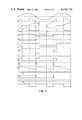
- FIG. 2shows a series of waveforms illustrating aspects of operation of the invention.
- an alternating current source(115-volts, 60 Hz A.C. and shown as waveform a of FIG. 2) is connected across terminals 10 and 12.
- Power supply 13is connected to these terminals, and it provides plus and minus 15 volts D.C. for operation of the circuitry shown in FIG. 1.
- Induction motor 14is connected between A.C. power terminal 10 and through triac 16 to the circuit ground, which in turn is connected to A.C. terminal 12. In this fashion, induction motor 14 is powered by an A.C. line voltage (waveform a of FIG.
- the A.C. voltagewhich is applied to induction motor 14, is also supplied to the inputs of voltage square wave shapers 20 and 22, shaper 22 providing a first phase, full wave, rectangular wave outut as shown in waveform e of FIG. 2, and shaper 22 providing a second, oppositely phased, full wave, rectangular wave output as shown in waveform f of FIG. 2.
- One output of each of voltage square wave shapers 20 and 22is fed to negative going pulse detector 28, which provides a negative spike output (waveform 1 of FIG. 2).
- Spike pulsesare then fed to ramp generator 30, which provides a ramp waveform each half cycle of the A.C. input as shown in waveform m of FIG. 2.
- This ramp waveformis applied to the plus, non-inverting, input of differential or operational amplifier 32 which functions as a zero crossing detector responsive to the combination of the ramp waveform and a power factor error signal (to be further described) supplied to the negative, inverting, input of amplifier 32.
- amplifier 32provides a variable width control signal output for the turn "on" of triac 33, and thereby triac 16, at a point which maintains the power factor of motor 14 at a commanded level.
- the two oppositely phased square wave signals (waveforms e and f) from square wave shapers 20 and 22are provided as a basis for voltage "on" time references each half cycle, or 120 cycles per second, for the development of voltage references at this rate for comparison, at the same rate, with the "on" time square wave signals representative of current "on” time and thereby the development of a signal representative of the operating power factor of motor 14.
- the "on" time current signalsare obtained by sensing the voltage across triac 16, it being noted in waveform c, showing motor current, and waveform d, showing triac voltage, that the trailing edge of one polarity portion of triac voltage marks the turn “on” of a current half cycle, and the leading edge of the next, opposite, polarity portion of triac voltage marks the turn “off” of that current half cycle.
- Sensing of triac voltageis accomplished by a voltage divider circuit consisting of resistors 35 and 37 connected across triac 16. The portion of triac voltage appearing across resistor 37 is provided as an input signal to current square wave shapers 24 and 26 which provide as outputs oppositely phased square waves as shown in waveforms g and h, respectively.
- the operating power factor signalis derived from a motor voltage/current phase angle, and the latter is obtained by the following process.
- the positive outputs of voltage square wave shaper 20 and current wave shaper 24are summed in summing device 34 to provide a pulse output as shown in waveform i of FIG. 2, and the positive outputs of voltage square wave shaper 22 and current square wave shaper 26 are summed in summing device 36 to provide a pulse output as shown in waveform j of FIG. 2.
- These two waveformsare combined by OR circuit 38 as shown in waveform k of FIG. 2 and, as combined, they are applied to summing junction 42 as an operating power factor signal.
- eachis turned “on” responsive to the turn “on” of a voltage half cycle and turned “off” by the next following the turn “off” of a current half wave cycle.
- the pulseseach have a width proportional to the phase angle between motor current and voltage, and occur at 120 cycle rates.
- the power factoris, of course, the cosine of the phase angle, and thus varies inversely with the phase angle. Accordingly, an increase in phase angle is indicative of a decrease in power factor, and vice versa.
- a control circuit signalis developed by the algebraic summing of a selected D.C. negative power factor control voltage with an integrated version of positive operating power factor signal (waveform k), this being done by applying a command voltage and a power factor signal to summing junction 42, which is an input to operational amplifier 46 connected as integrator 44.
- command voltage circuit 50which consists of potentiometer 52, across which is connected a negative 15-volt source. A selected portion of this voltage is provided by a resistor 54 connected between the movable arm of potentiometer 52 and summing junction 42.
- the effect of the summing of the voltagesis that, as will be further described, the "on" time of triac 16 is regulated as an inverse function of the value of the operational power factor signal voltage compared to the power factor command voltage in the manner described.
- the command voltage from circuit 50is set with motor 14 unloaded and by adjustment of potentiometer 52.
- a power factor(or phase angle between current and voltage) is determined by choosing the greatest power factor (smallest motor current/phase difference) at which the motor will operate over a range of loads to be encountered.
- the combination or sum of the command signal and power factor operating signal on summing junction 42is applied to the inverting input of operational amplifier 46.
- Amplifier 46is connected and operated as an integrator 44 by virtue of a capacitor 48 being connected between the output and inverting input of the amplifier.
- the positive or non-inverting input of operational amplifier 46is connected to ground.
- Integrator 44effectively smooths the pulse type operating power factor signal, and the combined signals are amplified and appear at the output of operational amplifier 46 as a negative control signal which shifts positively responsive to the presence of a higher than commanded power factor (indicated by equivalent smaller voltage/current phase angle) and shifts negatively when there is detected a lower than commanded power factor.
- the control signal from the output of operational amplifier 46is coupled through resistor 55 and is applied to the negative (inverting) input of operational amplifier 32, the ramp signal of waveform m being applied to the positive or non-inverting input of operational amplifier 32 as described above.
- the control signalhas the effect of varying the response of operational amplifier 32.
- a basically zero level control signalrepresented by reference line R1 of waveform n
- the output of operational amplifier 32will be essentially held negative by the ramp signal, resulting in a triggering output pulse shown by waveform o of amplifier 32, which stays on for all or essentially all of each full half cycle. This would typically be the case where a motor were operated at a low power factor setting, or would be the case for a basically fully loaded motor operating at a higher power factor.
- a typical value for a less than loaded motoris represented by reference line R2 of waveform p, the relative position of R2 with respect to the ramp signal being such that operational amplifier 32 would be triggered “on” during the latter portion of each ramp signal (waveform m), commencing with the intersection of the ramp signal with reference line R2.
- the output of operational amplifier 32is applied through diode 56 and resistor 58 as a negative pulse (e.g., waveforms o and q) to the gate input of triggering or buffer triac 33, and its output is connected to the trigger input of triac 16 which actually determines the duty cycle of power input each half cycle to motor 14. Accordingly, as an example, triac 16 is turned “on” each half cycle of the A.C. circuit for the pulse width of the negative pulse shown in waveform q for about 50% of the time of each half cycle of the A.C. input to motor 14. This turn "on" state of triac 16 is illustrated in waveform d and would typically occur for a medium loading of motor 14 as described.
- a negative pulsee.g., waveforms o and q
- this problemhas been solved. It has been solved by a positive feedback loop wherein the variable width negative pulse from operational amplifier 32 is coupled through resistor 45 to summing junction 42. Noting that this feedback pulse is of a negative polarity, it is of the same polarity as the command voltage, and of the opposite polarity to the operating power factor signal. With this fed back signal summed with the other two signals, the effect is to increase the response of operational amplifier 46 adequately to create a change in control voltage level applied to the inverting input of operational amplifier 46 to cause a greater pulse width output of operational amplifier 32 upon an increased load being applied to motor 14. This effectively prevents motor stalling when the power factor set by command voltage device 50 is set to a point quite close to the stalling point of motor 14 without load. Thus, it is believed that essentially the full potential for power savings with a factor type control system has been achieved.
Landscapes
- Engineering & Computer Science (AREA)
- Power Engineering (AREA)
- Control Of Ac Motors In General (AREA)
Abstract
Description
Claims (10)
Priority Applications (1)
| Application Number | Priority Date | Filing Date | Title |
|---|---|---|---|
| US06/297,524US4439718A (en) | 1981-08-28 | 1981-08-28 | Motor power control circuit for A.C. induction motors |
Applications Claiming Priority (1)
| Application Number | Priority Date | Filing Date | Title |
|---|---|---|---|
| US06/297,524US4439718A (en) | 1981-08-28 | 1981-08-28 | Motor power control circuit for A.C. induction motors |
Related Child Applications (1)
| Application Number | Title | Priority Date | Filing Date |
|---|---|---|---|
| US06/350,472Continuation-In-PartUS4417190A (en) | 1981-03-16 | 1982-02-19 | Control system for an induction motor with energy recovery |
Publications (1)
| Publication Number | Publication Date |
|---|---|
| US4439718Atrue US4439718A (en) | 1984-03-27 |
Family
ID=23146665
Family Applications (1)
| Application Number | Title | Priority Date | Filing Date |
|---|---|---|---|
| US06/297,524Expired - LifetimeUS4439718A (en) | 1981-08-28 | 1981-08-28 | Motor power control circuit for A.C. induction motors |
Country Status (1)
| Country | Link |
|---|---|
| US (1) | US4439718A (en) |
Cited By (28)
| Publication number | Priority date | Publication date | Assignee | Title |
|---|---|---|---|---|
| US4972134A (en)* | 1988-05-02 | 1990-11-20 | Whirlpool Corporation | Motor control circuit for automatic washer |
| US4990002A (en)* | 1988-09-12 | 1991-02-05 | Ametek, Inc. | Motor control circuit |
| US5008608A (en)* | 1989-12-26 | 1991-04-16 | Allen-Bradley Company, Inc. | Controller for starting and stopping electric motors |
| US5151642A (en)* | 1990-05-03 | 1992-09-29 | Allen-Bradley Company, Inc. | Apparatus for controlling an electric motor |
| US5159657A (en)* | 1989-01-23 | 1992-10-27 | Siemens Aktiengesellschaft | Method and apparatus for controlling single or polyphase a.c. power controllers |
| US5304911A (en)* | 1992-12-14 | 1994-04-19 | Energy Consortium Inc | Power control system for an A.C. induction motor |
| US5329223A (en)* | 1992-06-26 | 1994-07-12 | Green Technologies, Inc. | Ideal voltage controller for conserving energy in inductive loads |
| WO1994017586A1 (en)* | 1993-01-19 | 1994-08-04 | Condyne Technology, Inc. | Single-phase induction motor safety controller |
| US5444359A (en)* | 1992-06-26 | 1995-08-22 | Green Technologies, Inc. | Load sensitive variable voltage motor controller |
| US5670858A (en)* | 1991-06-03 | 1997-09-23 | Condyne Technology, Inc. | Single-phase induction motor safety controller |
| US5747972A (en)* | 1995-01-11 | 1998-05-05 | Microplanet Ltd. | Method and apparatus for electronic power control |
| GB2332108A (en)* | 1997-12-05 | 1999-06-09 | Samsung Kwang-Ju Electronics Co Ltd | Motor phase control apparatus |
| US6737827B2 (en) | 2001-04-10 | 2004-05-18 | Enviro World Systems, Inc. | Method and apparatus to control input to AC induction motors |
| US6836099B1 (en) | 2001-08-10 | 2004-12-28 | Sal G. Amarillas | Electrical power conservation apparatus and method |
| US20070024250A1 (en)* | 2005-08-01 | 2007-02-01 | Enviroworld Systems, Inc. | Method and apparatus for controlling the input to 3-phase AC induction motors |
| US20080197819A1 (en)* | 1995-01-11 | 2008-08-21 | John Thompson | Method and apparatus for electronic power control |
| US20090051344A1 (en)* | 2007-08-24 | 2009-02-26 | Lumsden John L | Triac/scr-based energy savings device, system and method |
| US7638966B1 (en) | 2008-09-03 | 2009-12-29 | Alexander Pummer | Voltage control and power factor correction in AC induction motors |
| US20100013427A1 (en)* | 2007-09-14 | 2010-01-21 | Kelley Paul H | Motor controller system and method for maximizing energy savings |
| US20100102771A1 (en)* | 2008-10-24 | 2010-04-29 | Nicholas Anderson | Energy saver delay circuit for ac induction motors |
| US20100320956A1 (en)* | 2007-09-14 | 2010-12-23 | The Powerwise Group, Inc. | Energy Saving System and Method for Devices with Rotating or Reciprocating Masses |
| US20110057601A1 (en)* | 2009-09-10 | 2011-03-10 | Hiltbold Gordon E | Current injection circuit for delaying the full operation of a power factor control circuit for ac induction motors |
| US20110080130A1 (en)* | 2009-09-08 | 2011-04-07 | The Powerwise Group, Inc. | Method to save energy for devices with rotating or reciprocating masses |
| US8085009B2 (en) | 2007-08-13 | 2011-12-27 | The Powerwise Group, Inc. | IGBT/FET-based energy savings device for reducing a predetermined amount of voltage using pulse width modulation |
| US8120307B2 (en) | 2007-08-24 | 2012-02-21 | The Powerwise Group, Inc. | System and method for providing constant loading in AC power applications |
| US20120229070A1 (en)* | 2011-03-07 | 2012-09-13 | Marcoccia Mario M | Single Phase Motor Energy Economizer for Regulating the Use of Electricity |
| US8619443B2 (en) | 2010-09-29 | 2013-12-31 | The Powerwise Group, Inc. | System and method to boost voltage |
| US8698447B2 (en) | 2007-09-14 | 2014-04-15 | The Powerwise Group, Inc. | Energy saving system and method for devices with rotating or reciprocating masses |
Citations (6)
| Publication number | Priority date | Publication date | Assignee | Title |
|---|---|---|---|---|
| US3497779A (en)* | 1966-11-25 | 1970-02-24 | Westinghouse Electric Corp | Limit of the rate of rise of current in a parallel control scheme |
| US4052648A (en)* | 1976-07-19 | 1977-10-04 | The United States Of America As Represented By The Administrator Of The National Aeronautics And Space Administration | Power factor control system for ac induction motors |
| US4229690A (en)* | 1977-04-20 | 1980-10-21 | Techno-Instruments Ltd. | Single phase power control circuit |
| US4361792A (en)* | 1980-05-06 | 1982-11-30 | Chesebrough-Pond's Inc. | Digital induction motor control system |
| US4387329A (en)* | 1980-03-21 | 1983-06-07 | Electronic Assemblers Company | Three phase power-factor control system for A.C. induction motors |
| US4388578A (en)* | 1980-07-07 | 1983-06-14 | Cynex Manufacturing Corporation | Power factor controller |
- 1981
- 1981-08-28USUS06/297,524patent/US4439718A/ennot_activeExpired - Lifetime
Patent Citations (6)
| Publication number | Priority date | Publication date | Assignee | Title |
|---|---|---|---|---|
| US3497779A (en)* | 1966-11-25 | 1970-02-24 | Westinghouse Electric Corp | Limit of the rate of rise of current in a parallel control scheme |
| US4052648A (en)* | 1976-07-19 | 1977-10-04 | The United States Of America As Represented By The Administrator Of The National Aeronautics And Space Administration | Power factor control system for ac induction motors |
| US4229690A (en)* | 1977-04-20 | 1980-10-21 | Techno-Instruments Ltd. | Single phase power control circuit |
| US4387329A (en)* | 1980-03-21 | 1983-06-07 | Electronic Assemblers Company | Three phase power-factor control system for A.C. induction motors |
| US4361792A (en)* | 1980-05-06 | 1982-11-30 | Chesebrough-Pond's Inc. | Digital induction motor control system |
| US4388578A (en)* | 1980-07-07 | 1983-06-14 | Cynex Manufacturing Corporation | Power factor controller |
Non-Patent Citations (2)
| Title |
|---|
| "Improved Power Factor Controller", N.A.S.A., G. G. Marshall, Space Flight Center, NASA Tech. Briefs, Summer 1980, vol. 5, No. 2, MFS-25323. |
| Improved Power Factor Controller , N.A.S.A., G. G. Marshall, Space Flight Center, NASA Tech. Briefs, Summer 1980, vol. 5, No. 2, MFS 25323.* |
Cited By (54)
| Publication number | Priority date | Publication date | Assignee | Title |
|---|---|---|---|---|
| US4972134A (en)* | 1988-05-02 | 1990-11-20 | Whirlpool Corporation | Motor control circuit for automatic washer |
| US4990002A (en)* | 1988-09-12 | 1991-02-05 | Ametek, Inc. | Motor control circuit |
| US5159657A (en)* | 1989-01-23 | 1992-10-27 | Siemens Aktiengesellschaft | Method and apparatus for controlling single or polyphase a.c. power controllers |
| US5008608A (en)* | 1989-12-26 | 1991-04-16 | Allen-Bradley Company, Inc. | Controller for starting and stopping electric motors |
| EP0435038A3 (en)* | 1989-12-26 | 1992-11-04 | Allen-Bradley Company, Inc. | Controller for starting and stopping electric motors |
| US5151642A (en)* | 1990-05-03 | 1992-09-29 | Allen-Bradley Company, Inc. | Apparatus for controlling an electric motor |
| US5670858A (en)* | 1991-06-03 | 1997-09-23 | Condyne Technology, Inc. | Single-phase induction motor safety controller |
| US5329223A (en)* | 1992-06-26 | 1994-07-12 | Green Technologies, Inc. | Ideal voltage controller for conserving energy in inductive loads |
| US5444359A (en)* | 1992-06-26 | 1995-08-22 | Green Technologies, Inc. | Load sensitive variable voltage motor controller |
| US5304911A (en)* | 1992-12-14 | 1994-04-19 | Energy Consortium Inc | Power control system for an A.C. induction motor |
| US5389869A (en)* | 1992-12-14 | 1995-02-14 | Energy Consortium, Inc. | Power control system for an A.C. induction motor |
| WO1994017586A1 (en)* | 1993-01-19 | 1994-08-04 | Condyne Technology, Inc. | Single-phase induction motor safety controller |
| US20080197819A1 (en)* | 1995-01-11 | 2008-08-21 | John Thompson | Method and apparatus for electronic power control |
| US7595613B2 (en) | 1995-01-11 | 2009-09-29 | Microplanet Inc. | Method and apparatus for electronic power control |
| US5747972A (en)* | 1995-01-11 | 1998-05-05 | Microplanet Ltd. | Method and apparatus for electronic power control |
| GB2332108B (en)* | 1997-12-05 | 2000-02-02 | Kwangju Electronics Co Limited | Motor phase control apparatus |
| GB2332108A (en)* | 1997-12-05 | 1999-06-09 | Samsung Kwang-Ju Electronics Co Ltd | Motor phase control apparatus |
| US6737827B2 (en) | 2001-04-10 | 2004-05-18 | Enviro World Systems, Inc. | Method and apparatus to control input to AC induction motors |
| US20040174134A1 (en)* | 2001-04-10 | 2004-09-09 | Enviro World Systems, Inc. | Method and apparatus to control input to AC induction motors |
| US6954046B2 (en) | 2001-04-10 | 2005-10-11 | Enviro World Systems, Inc. | Method and apparatus to control input to AC induction motors |
| US6836099B1 (en) | 2001-08-10 | 2004-12-28 | Sal G. Amarillas | Electrical power conservation apparatus and method |
| US20070024250A1 (en)* | 2005-08-01 | 2007-02-01 | Enviroworld Systems, Inc. | Method and apparatus for controlling the input to 3-phase AC induction motors |
| US7378821B2 (en) | 2005-08-01 | 2008-05-27 | Enviro World Technologies, Inc | Method and apparatus using VAR measurements to control power input to a three-phase induction motor circuit |
| US8085009B2 (en) | 2007-08-13 | 2011-12-27 | The Powerwise Group, Inc. | IGBT/FET-based energy savings device for reducing a predetermined amount of voltage using pulse width modulation |
| US9716431B2 (en) | 2007-08-13 | 2017-07-25 | The Powerwise Group, Inc. | IGBT/FET-based energy savings device for reducing a predetermined amount of voltage using pulse width modulation |
| US8723488B2 (en) | 2007-08-13 | 2014-05-13 | The Powerwise Group, Inc. | IGBT/FET-based energy savings device for reducing a predetermined amount of voltage using pulse width modulation |
| US8120307B2 (en) | 2007-08-24 | 2012-02-21 | The Powerwise Group, Inc. | System and method for providing constant loading in AC power applications |
| US20090051344A1 (en)* | 2007-08-24 | 2009-02-26 | Lumsden John L | Triac/scr-based energy savings device, system and method |
| US8085010B2 (en) | 2007-08-24 | 2011-12-27 | The Powerwise Group, Inc. | TRIAC/SCR-based energy savings device for reducing a predetermined amount of voltage using pulse width modulation |
| US20100117588A9 (en)* | 2007-09-14 | 2010-05-13 | Kelley Paul H | Motor controller system and method for maximizing energy savings |
| US9628015B2 (en) | 2007-09-14 | 2017-04-18 | The Powerwise Group, Inc. | Energy saving system and method for devices with rotating or reciprocating masses |
| US8810190B2 (en) | 2007-09-14 | 2014-08-19 | The Powerwise Group, Inc. | Motor controller system and method for maximizing energy savings |
| US20100320956A1 (en)* | 2007-09-14 | 2010-12-23 | The Powerwise Group, Inc. | Energy Saving System and Method for Devices with Rotating or Reciprocating Masses |
| US20100013427A1 (en)* | 2007-09-14 | 2010-01-21 | Kelley Paul H | Motor controller system and method for maximizing energy savings |
| US8698447B2 (en) | 2007-09-14 | 2014-04-15 | The Powerwise Group, Inc. | Energy saving system and method for devices with rotating or reciprocating masses |
| US9716449B2 (en) | 2007-09-14 | 2017-07-25 | The Powerwise Group, Inc. | Energy saving system and method for devices with rotating or reciprocating masses |
| US8823314B2 (en) | 2007-09-14 | 2014-09-02 | The Powerwise Group, Inc. | Energy saving system and method for devices with rotating or reciprocating masses |
| US7855524B2 (en) | 2008-09-03 | 2010-12-21 | John E. Powers | Voltage control and power factor correction in AC induction motors |
| US7638966B1 (en) | 2008-09-03 | 2009-12-29 | Alexander Pummer | Voltage control and power factor correction in AC induction motors |
| US8421399B2 (en)* | 2008-10-24 | 2013-04-16 | Energy Innovative Products, Llc | Energy saver delay circuit for AC induction motors |
| US20100102771A1 (en)* | 2008-10-24 | 2010-04-29 | Nicholas Anderson | Energy saver delay circuit for ac induction motors |
| US9240745B2 (en) | 2009-09-08 | 2016-01-19 | The Powerwise Group, Inc. | System and method for saving energy when driving masses having periodic load variations |
| US8698446B2 (en) | 2009-09-08 | 2014-04-15 | The Powerwise Group, Inc. | Method to save energy for devices with rotating or reciprocating masses |
| US20110080130A1 (en)* | 2009-09-08 | 2011-04-07 | The Powerwise Group, Inc. | Method to save energy for devices with rotating or reciprocating masses |
| US8575881B2 (en)* | 2009-09-10 | 2013-11-05 | Energy Innovative Products, Inc. | Current injection circuit for delaying the full operation of a power factor control circuit for AC induction motors |
| US20110057601A1 (en)* | 2009-09-10 | 2011-03-10 | Hiltbold Gordon E | Current injection circuit for delaying the full operation of a power factor control circuit for ac induction motors |
| US8619443B2 (en) | 2010-09-29 | 2013-12-31 | The Powerwise Group, Inc. | System and method to boost voltage |
| US8362735B2 (en)* | 2011-03-07 | 2013-01-29 | Protective Energy Economizer Technology | Single phase motor energy economizer for regulating the use of electricity |
| US8633668B2 (en)* | 2011-03-07 | 2014-01-21 | Protective Energy Economizer Technology | Single phase motor energy economizer for regulating the use of electricity |
| US9425714B2 (en) | 2011-03-07 | 2016-08-23 | Protective Energy Economizer Technology | Single phase motor energy economizer for regulating the use of electricity |
| US8502492B2 (en)* | 2011-03-07 | 2013-08-06 | Protective Energy Economizer Technology | Single phase motor energy economizer for regulating the use of electricity |
| US20130088183A1 (en)* | 2011-03-07 | 2013-04-11 | Protective Energy Economizer Technology | Single Phase Motor Energy Economizer for Regulating the Use of Electricity |
| US20120229070A1 (en)* | 2011-03-07 | 2012-09-13 | Marcoccia Mario M | Single Phase Motor Energy Economizer for Regulating the Use of Electricity |
| US10116239B2 (en) | 2011-03-07 | 2018-10-30 | Protective Energy Economizer Technology | Single phase motor energy economizer for regulating the use of electricity |
Similar Documents
| Publication | Publication Date | Title |
|---|---|---|
| US4439718A (en) | Motor power control circuit for A.C. induction motors | |
| US4426614A (en) | Pulsed thyristor trigger control circuit | |
| US4266177A (en) | Power factor control system for AC induction motors | |
| US4433276A (en) | Three phase power factor controller | |
| US4469998A (en) | Three-phase power factor controller with induced emf sensing | |
| US4052648A (en) | Power factor control system for ac induction motors | |
| US4404511A (en) | Motor power factor controller with a reduced voltage starter | |
| US4315305A (en) | Controlled D-C power supply | |
| US4417190A (en) | Control system for an induction motor with energy recovery | |
| US4039913A (en) | Universal electric motor speed control | |
| US4400657A (en) | Triac failure detector | |
| US4291264A (en) | Power factor control system for inverter-driven a-c induction motor | |
| US5389869A (en) | Power control system for an A.C. induction motor | |
| US4358730A (en) | AC Power control circuit | |
| US3308307A (en) | Servo amplifier utilizing composite waveform of sawtooth with high frequency signal imposed thereon | |
| US3767998A (en) | Constant current power supply | |
| US4489264A (en) | Power Control for AC motor | |
| US4042868A (en) | Stepper motor control apparatus | |
| EP0051903B1 (en) | Three phase power factor controller | |
| US3436636A (en) | Differential preamplifier network for a sample-data motor speed control | |
| US4599552A (en) | Generator voltage regulator | |
| EP0637127A1 (en) | Three-phase electronic inverter for variable speed motor and method of operating same | |
| US3758844A (en) | Control circuit for load having measureable coefficient of resistance | |
| US2937327A (en) | Pulsing methods and apparatus for the control of movable members | |
| US3258678A (en) | Transistorized gating circuit for controlled rectifiers |
Legal Events
| Date | Code | Title | Description |
|---|---|---|---|
| AS | Assignment | Owner name:UNITED STATES OF AMERICA AS REPRESENTED BY THE ADM Free format text:ASSIGNMENT OF ASSIGNORS INTEREST.;ASSIGNOR:NOLA, FRANK J.;REEL/FRAME:003916/0180 Effective date:19810823 Owner name:UNITED STATES OF AMERICA AS REPRESENTED BY THE ADM Free format text:ASSIGNMENT OF ASSIGNORS INTEREST;ASSIGNOR:NOLA, FRANK J.;REEL/FRAME:003916/0180 Effective date:19810823 | |
| STCF | Information on status: patent grant | Free format text:PATENTED CASE | |
| MAFP | Maintenance fee payment | Free format text:PAYMENT OF MAINTENANCE FEE, 4TH YEAR, PL 96-517 (ORIGINAL EVENT CODE: M170); ENTITY STATUS OF PATENT OWNER: LARGE ENTITY Year of fee payment:4 | |
| MAFP | Maintenance fee payment | Free format text:PAYMENT OF MAINTENANCE FEE, 8TH YEAR, PL 96-517 (ORIGINAL EVENT CODE: M171); ENTITY STATUS OF PATENT OWNER: LARGE ENTITY Year of fee payment:8 | |
| MAFP | Maintenance fee payment | Free format text:PAYMENT OF MAINTENANCE FEE, 12TH YEAR, LARGE ENTITY (ORIGINAL EVENT CODE: M185); ENTITY STATUS OF PATENT OWNER: LARGE ENTITY Year of fee payment:12 |