US4439049A - Temperature scanner - Google Patents
Temperature scannerDownload PDFInfo
- Publication number
- US4439049A US4439049AUS06/345,086US34508682AUS4439049AUS 4439049 AUS4439049 AUS 4439049AUS 34508682 AUS34508682 AUS 34508682AUS 4439049 AUS4439049 AUS 4439049A
- Authority
- US
- United States
- Prior art keywords
- strip
- temperature
- display
- scanner
- analysis means
- Prior art date
- Legal status (The legal status is an assumption and is not a legal conclusion. Google has not performed a legal analysis and makes no representation as to the accuracy of the status listed.)
- Expired - Lifetime
Links
Images


Classifications
- G—PHYSICS
- G01—MEASURING; TESTING
- G01J—MEASUREMENT OF INTENSITY, VELOCITY, SPECTRAL CONTENT, POLARISATION, PHASE OR PULSE CHARACTERISTICS OF INFRARED, VISIBLE OR ULTRAVIOLET LIGHT; COLORIMETRY; RADIATION PYROMETRY
- G01J5/00—Radiation pyrometry, e.g. infrared or optical thermometry
- G01J5/0022—Radiation pyrometry, e.g. infrared or optical thermometry for sensing the radiation of moving bodies
- G—PHYSICS
- G01—MEASURING; TESTING
- G01J—MEASUREMENT OF INTENSITY, VELOCITY, SPECTRAL CONTENT, POLARISATION, PHASE OR PULSE CHARACTERISTICS OF INFRARED, VISIBLE OR ULTRAVIOLET LIGHT; COLORIMETRY; RADIATION PYROMETRY
- G01J5/00—Radiation pyrometry, e.g. infrared or optical thermometry
- G01J5/02—Constructional details
- G01J5/06—Arrangements for eliminating effects of disturbing radiation; Arrangements for compensating changes in sensitivity
- G01J5/061—Arrangements for eliminating effects of disturbing radiation; Arrangements for compensating changes in sensitivity by controlling the temperature of the apparatus or parts thereof, e.g. using cooling means or thermostats
- G—PHYSICS
- G01—MEASURING; TESTING
- G01N—INVESTIGATING OR ANALYSING MATERIALS BY DETERMINING THEIR CHEMICAL OR PHYSICAL PROPERTIES
- G01N25/00—Investigating or analyzing materials by the use of thermal means
- G01N25/72—Investigating presence of flaws
Definitions
- This inventionrelates to a temperature scanner for detecting the temperatures or relative temperatures of positions on the surface of a hot steel strip moving relative to said scanner and in particular to analysis and display means used in such a scanner.
- Temperature scanners of this kindhave many applications but are particularly useful in steel rolling mills.
- a hot steel strip rolling millfor example a hot steel strip is progressively lengthened and reduced in thickness by being passed through a train of rolling stands. The hotter the steel is, the more ductile it becomes.
- This howeverleads to the disadvantage that an uneven temperature distribution over the strip will result in some portions being lengthened and reduced in thickness to a greater extent than other portions.
- a rolling millwhere high speeds are achieved by the strip as a result of its being lengthened, such uneven elongation can result in dangerous buckling or deviation of the strip from its intended path. Even if the uneven treatment is not sufficient to cause an accident the quality of the strip will be adversely affected by damage to the strip edges, caused by the strip scraping against stops on the strip table.
- FR 2397627discloses an infra-red pyrometer and mirror for scanning the temperature of the output of a sintering plant.
- the information desiredis displayed solely as temperature profiles.
- the device disclosedis first of all unsuitable for use in a hot steel strip rolling mill for several reasons.
- a sintering linehas a very low speed in contrast to a hot strip mill, the device is not suitable for accurately measuring temperatures between 800° and 1000° C. as encountered in a hot strip mill and furthermore the device cannot determine the temperature of a fast moving hot steel strip having an emission coefficient of 0.8.
- a sintering lineis confined by vertical walls and the device is incapable of determining the width of a steel strip.
- the display of the information collected by the infra-red scannercan only be present as temperature profiles which thus severely limits the ease of comprehension and choice as to the most convenient form of presentation for the operator.
- the object of the present inventionis to provide a scanner, specifically for hot steel strip, which provides useful displayed information for operators and for quality control.
- the scanner of the inventionprovides three possible modes of display, any one of which may be selected.
- a map of the hot surfaceis displayed, which enables easy overall monitoring of the condition of the surface, e.g. a hot rolled strip.
- the mapmay show the whole surface or may be made up from a large number of spaced apart scanned areas of the surface.
- This mapmay be a "black/white" display, black for areas below a given threshold temperature and white for areas above the given temperature (or vice versa).
- the data used to provide the map displaycan be reprocessed with respect to a different threshold temperature, to provide a different map.
- the second modeit displays simultaneously temperature profiles of a plurality of different scanned areas.
- parts of the display representing temperatures above a given reference levelmay be distinguished from those below the reference level.
- the devicethus advantageously provides a readily visible, accessible and understandable means of assessing the temperature distribution over the scanned surface.
- the devicealso has the advantage that it is possible to observe the temperature distribution of an entire strip after it has passed through the mill and that it is also possible to study the temperature profile of the strip as it passes the scanner.
- the present inventionalso has the advantage that it is able to act as an edge detector for the strip and it is thus capable of determining the width of the strip and whether the strip is keeping to its preferred path. This is a result of the temperature of the strip being higher than that of its surroundings.
- FIG. 1shows analysis and display means associated with a photocell and scanning means arranged above a strip being passed through a pair of rollers
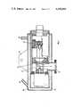
- FIG. 2is a cross sectional view of the scanning means shown in FIG. 1,
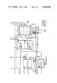
- FIG. 3is a block diagram of the electronic analysis means
- FIGS. 4, 5 and 6show representations of three different display modes as they appear on the display means.
- FIG. 1a photocell and associated scanning means 1 are shown mounted above a hot strip 2 being passed between rollers 3. In each scan the photocell and scanning means 1 observes the area of the strip indicated by the dashed lines 4 which is perpendicular to the direction in which it passes underneath the photocell and scanning means.
- the output from the photocell 1is then passed via connecting lead 5 to electronic analysis means 6.
- the output from the electronic analysis means 6is then passed to display means 7 via connecting lead 8.
- the display means 7comprises a storage monitor (e.g. one made by Tektronix, model No. 603A).
- the photocell and associated scanning means 1are shown in greater detail in FIG. 2.
- a gold coated mirror 9is rotated by a motor 10 and reflects radiation passing through a pyrex observation port 11 onto a germanium photocell 12 via a pyrex condensing lens 13.
- the mirror 9is rotated with its axis parallel to the direction of travel of the surface being observed and scans an angle of 60° through the port 11.
- the minimum angle which the strip should subtend at the mirroris 4°.
- the photocell and scanner unitis suspended above the strip using mounting lug 14.
- the unitis preferably only 1 to 2 times the width of the strip above the strip (often only about 2.5 m) where it may be extremely hot, the unit is provided with a liquid cooling jacket 15 with inlet and outlets 16.
- the photocell usedis preferably one with a low sensitivity to both visible light and the wavelength at which IR absorption by vapor occurs.
- the photocellis provided with an infra red filter and is sensitive over the range 0.8-0.2 um with a maximum sensitivity at 1.55 um.
- the photocellthus has a high sensitivity for radiation emitted by the hot strip but a low sensitivity to the effects of water vapour and variations in the emission coefficient of the strip. In a rolling mill, there is likely to be much water vapour in the atmosphere.
- the surface area observed at any one instantis approximately 18 mm in diameter and as the scanning frequency is 25 s -1 the photocell is able to scan a series of substantially parallel strips on the strip surface. Scanning occurs during about 6.7 mS of the 40 mS that each rotation of the mirror lasts and the photocell produces a voltage of 6.206 volts via a built-in preamplifier when receiving radiation from a black body at 1100° C.
- the output from the photocell and scanner unitis passed to the electronic analysis means 6 via lead 5.
- the photocell and scanner unitis arranged so that a 0.5 mS trigger pulse is also sent to the analysis means 6 along lead 5, 6° or 0.7 mS before the mirror 9 starts to scan through the aperture 11.
- this signal and a zero level signalare passed to a circuit 17 comprising a differential amplifier. Random voltages induced in the lead 5 are thus eliminated.
- a strip simulator circuit 18may be switched into the circuit instead of the photocell and scanner output in order to test the device.
- the strip simulator circuit 18produces a synthesized temperature signal every 40 mS using an oscillator and amplitude compression circuit.
- the temperature signalis sent to the lineariser circuit 19 via an emission coefficent resistor and is amplified in the lineariser circuit 19 by a factor of 1.25 (that being the reciprocal of the emission coefficient of steel).
- the lineariser circuit 19converts the signal to a linear temperature signal of 10 mV per °C.
- the temperature signalthen passes to the image height amplifier circuit 20 via a switch which selects a scale of 0.1 volt per 20,50 or 100 cm for temperatures above 500° C. when the "16 line" or “continuous" display mode is used.
- the temperature signalis then transmitted to the Y input of the display means 7 via a switching system 21.
- the zero levelmay be adjusted by potentiometer 22 and the step height by potentiometer 23.
- the temperature signalis also fed to the circuit 24 which contains the temperature marking circuit 25. This circuit 25 compares the input temperature signal with a reference level set by either of potentiometers 26a or 26b.
- the signalindicates a temperature lower than that corresponding to the reference level the signal is fed to the Z or brightness input of the display means via switching circuit 21 and a multivibrator which suppresses the signal 20,000 times a second thus creating a dotted line. If the temperature is above the reference level the signal is fed directly to the switching circuit 21 thus forming a continuous line. When the "black/white" display mode is selected the comparator will completely suppress the Z input signal when the temperature signal is below the reference level.
- the temperature signal from the lineariser 19is also fed to the circuit 27 which contains the strip detector circuit 28.
- Thisvia a delay to prevent premature operation between scans or when cold areas of the strip are detected, indicates that a strip is present using an LED 29 via circuit 30 and also permanently switches the erase switch on the display means 7 on, as long as a strip is present and the switch 31 is set to erase.
- the monitor screenwill thus be erased when a new strip appears and cannot be erased in between by pressing the erase switch on the display.
- the strip detector circuit 28also, via switch 31b, switches on the start time switch circuit 32 which is also in circuit 27.
- the strip detector circuit 28also switches on the strip length time base circuit 33 which forms part of circuit 34.
- the strip length time base circuit 33provides the X input to the display during the use of the "black/white" display mode.
- the strip detector 28also provides a strip width voltage signal which is used to indicate the width of the strip.
- the strip edgesare determined by taking the temperature at any instant which is midway between the peak value and 500° C. to represent the position of the strip edges.
- the strip width signalis fed to the strip edge detector circuit 35 which forms another part of circuit 34.
- the strip edge detector circuit 35provides a short positive pulse at the Z input of the monitor so that lines representing the strip edges are displayed during the black/white display mode. This pulse appears after the detection of the edge and to compensate for this delay the Y time base voltage from the strip width time base circuit 36 is also delayed.
- the trigger signals from the differential amplifier 17are transmitted by the trigger pulse divider circuit 37 in circuit 24 only if they exceed 7 volts. In this way extraneous pulses below 7 volts may be eliminated.
- a first output 38 of the divider circuit 37all trigger pulses are emitted.
- the second output 39only pulses which start with the arrival of those pulses arriving immediately after the end of the start or interval time are emitted.
- the start timeis the length of time between the detection of the strip and the display of the first temperature profile and the interval time is the time between the display of successive profiles in the case of the "16 line" display mode.
- the signals from the outputs 38 and 39then travel via the tigger control circuit of circuit 21 to switch 40a (which may be set to “adjust” or “measure” positions) and thence to the step pulse source circuit 41 in circuit 27 and to the strip width time base circuit 36 when the switch 40a is in the "measure” position.
- switch 40aWhen the switch 40a is in the "adjust” position, the output from the first output 38 alone is fed directly to the step pulse circuit 41 and to the strip width time base circuit 36.
- the step pulse source circuit 41passes incoming pulses to the step counter circuit 42 as long as this does not block such signals by sending the step pulse source circuit a stop measuring signal.
- the step counter circuit 42counts a plurality of steps down during the display of a plurality of temperature profiles. In this example 16 are counted (hence "16 line” display mode). If the strip passes earlier the counter will stop.
- the stepcounterwill be reset and stopped if the reset entry input 43 is at a low voltage, for example after the temperature signal ceases and if switch 44 is set to the "continuous" display mode position.
- the stepcounteralso operated during the black/white display mode, in this case the resulting image height is not passed to the display. When switching over from "black/white” display mode to the "16 line” display mode the stepcounter is reset as the switch 44 is a "break before make” switch.
- the start and interval time switch circuit 32comprises three monostable flipflops. These are each associated with either the start time, an auxiliary time (0.8 s) or the interval time.
- the "auxiliary time” and “interval time” flip flopsform a circuit which is switched on by the start time flip flop.
- the "auxiliary time” flip flopswitches on an AND gate in circuit 24 so that the next trigger edge is passed to output 39.
- the circuit 27also blocks the "store" function of the display during the "continuous" display mode and when switch 40 is set to "adjust".
- the switching system circuit 21connects the X,Y and Z display inputs to the correct outputs and selects the correct trigger pulses for the "16 line” or "black/white” display modes.
- the time base for the strip widthis fed to the X input in the "continuous" and “16 line” display modes and to the Y input via an amplifier having an amplification factor of 0.8 during the "black/white” display mode.
- the power supply circuit 45receives 2 ⁇ 18 volts and the output voltage is ⁇ 15 v.
- the power transistorsare mounted on the mounting plate of the box containing the analysis means.
- the operator of this embodiment of the present inventionthus has a choice of three display modes, to each of which he may make a number of adjustments.
- On selecting the continuous display using switch 44the operator will observe a temperature profile of the strip which is continuously updated as the strip passes the detector.
- the operationmay select either of potentiometers 26a or 26b, one of which may be a preset one within the analysis means and the other of which may be manually adjustable by the operator, and then he may set either to determine a reference temperature below which the temperature profile on the screen will appear as a dotted line as shown in FIG. 4.
- the switch 31performs a similar function during the black/white display mode.
- the temperature profiles displayed during the "16 line" display modewill also appear as dotted lines when below the set reference temperature as in the continuous display.
- the strip position on the displaymay be adjusted using potentiometer 48. This will move the display in the X direction during the "continuous” and “16 line” display modes and in the Y direction during the "black/white” display mode.
Landscapes
- Physics & Mathematics (AREA)
- General Physics & Mathematics (AREA)
- Spectroscopy & Molecular Physics (AREA)
- Health & Medical Sciences (AREA)
- Life Sciences & Earth Sciences (AREA)
- Chemical & Material Sciences (AREA)
- Analytical Chemistry (AREA)
- Biochemistry (AREA)
- General Health & Medical Sciences (AREA)
- Immunology (AREA)
- Pathology (AREA)
- Radiation Pyrometers (AREA)
Abstract
Description
Claims (7)
Applications Claiming Priority (2)
| Application Number | Priority Date | Filing Date | Title |
|---|---|---|---|
| EP81200070AEP0057290A1 (en) | 1981-02-02 | 1981-02-02 | Temperature scanner |
| EP81200070.1 | 1981-02-02 |
Publications (1)
| Publication Number | Publication Date |
|---|---|
| US4439049Atrue US4439049A (en) | 1984-03-27 |
Family
ID=8188104
Family Applications (1)
| Application Number | Title | Priority Date | Filing Date |
|---|---|---|---|
| US06/345,086Expired - LifetimeUS4439049A (en) | 1981-02-02 | 1982-02-02 | Temperature scanner |
Country Status (5)
| Country | Link |
|---|---|
| US (1) | US4439049A (en) |
| EP (1) | EP0057290A1 (en) |
| JP (1) | JPS57189032A (en) |
| CA (1) | CA1170742A (en) |
| MX (1) | MX150653A (en) |
Cited By (28)
| Publication number | Priority date | Publication date | Assignee | Title |
|---|---|---|---|---|
| US4559819A (en)* | 1983-05-17 | 1985-12-24 | Mannesmann Aktiengesellschaft | Selecting the cut-off end portion of rolled sheet stock |
| US4614567A (en)* | 1983-10-28 | 1986-09-30 | Firma Carl Still Gmbh & Co. Kg | Method and apparatus for selective after-quenching of coke on a coke bench |
| US4650345A (en)* | 1984-10-19 | 1987-03-17 | Institut Textile De France | Microwave radiometry method and device for measuring the temperature of a moving, textile material |
| US4671674A (en)* | 1984-04-24 | 1987-06-09 | Somafer | Process for the detection and recording of weak points or defects on hot iron and steel industry semifinished products |
| US4693615A (en)* | 1984-06-14 | 1987-09-15 | John Kyriakis | Non-contact temperature measurement of a static or moving target |
| US4746224A (en)* | 1985-12-19 | 1988-05-24 | Daido Tokushuko Kabushiki Kaisha | Scanning type, radiant-energy responsive temperature measuring apparatus |
| US4840496A (en)* | 1988-02-23 | 1989-06-20 | The United States Of America As Represented By The Administrator Of The National Aeronautics And Space Administration | Noncontact temperature pattern measuring device |
| US4860224A (en)* | 1985-05-21 | 1989-08-22 | 501 Tekscan Limited | Surface analysis spectroscopy apparatus |
| US5123144A (en)* | 1989-08-09 | 1992-06-23 | Maschinenfabrik Rieter Ag | Method and apparatus for establishing whether fiber material is contaminated with foreign objects |
| US5131758A (en)* | 1990-05-16 | 1992-07-21 | Administrator Of The National Aeronautics And Space Administration | Method of remotely characterizing thermal properties of a sample |
| US5294198A (en)* | 1991-10-01 | 1994-03-15 | Cincinnati Electronics Corporation | Infrared inspection system and method employing emissivity indications |
| US5562345A (en)* | 1992-05-05 | 1996-10-08 | The United States Of America As Represented By The Administrator Of The National Aeronautics And Space Administration | Method and apparatus for thermographically and quantitatively analyzing a structure for disbonds and/or inclusions |
| US6033107A (en)* | 1997-07-15 | 2000-03-07 | Temptronic Corporation | Temperature mapping system |
| US6373071B1 (en) | 1999-06-30 | 2002-04-16 | Applied Materials, Inc. | Real-time prediction of proximity resist heating and correction of raster scan electron beam lithography |
| US20030164017A1 (en)* | 2000-09-29 | 2003-09-04 | Konrad Thiele | Method and device for operating a hot rolling train with at least one edger |
| US20040218660A1 (en)* | 2002-09-25 | 2004-11-04 | Illinois Tool Works Inc. | Hot melt adhesive detection methods and systems |
| US20050041723A1 (en)* | 2002-09-25 | 2005-02-24 | Heerdt Dieter B. | Hot melt adhesive detection methods |
| US20050111520A1 (en)* | 2002-08-27 | 2005-05-26 | Ircon, Inc. | Method and device for normalizing temperature variations |
| US20060029121A1 (en)* | 2004-08-03 | 2006-02-09 | Daimlerchrysler Ag | Test apparatus and test method for the nondestructive testing in particular of membrane electrode assemblies for use in fuel cells, which can be integrated in production |
| US20060137418A1 (en)* | 2003-09-15 | 2006-06-29 | Clark John D | Methods and apparatus for monitoring and conditioning strip material |
| US20090008019A1 (en)* | 2006-04-03 | 2009-01-08 | Sika Technology Ag | Use of Infrared Thermography as an Agent for Determining the Hardening Course of a Two-Component Composition |
| DE102007042560A1 (en)* | 2007-09-07 | 2009-04-30 | Siemens Ag | Apparatus for determining a temperature of a hot rolling stock and method for controlling and / or regulating a temperature of a hot rolling stock |
| US20090196324A1 (en)* | 2008-02-01 | 2009-08-06 | Land Instruments International Limited | Real-Time Line Scan Extraction from Infrared Images Using the Wedge Method in Industrial Environments |
| CN101837374A (en)* | 2009-03-20 | 2010-09-22 | 西门子Vai金属科技有限公司 | Edge flatness monitoring |
| US20110018721A1 (en)* | 2008-02-01 | 2011-01-27 | Land Instruments International Limited | Method and apparatus for measuring the temperature of a sheet material |
| WO2012171627A1 (en)* | 2011-06-14 | 2012-12-20 | Tata Steel Nederland Technology B.V. | Method and device of determining a tracking characteristic and/or strip width of a moving strip |
| CN108981926A (en)* | 2018-08-03 | 2018-12-11 | 合肥工业大学 | A kind of temperature acquisition system applied to band-like Nonlubricated bearing production line |
| US11919060B2 (en) | 2021-08-16 | 2024-03-05 | The Bradbury Co., Inc. | Methods and apparatus to control roll-forming processes |
Families Citing this family (7)
| Publication number | Priority date | Publication date | Assignee | Title |
|---|---|---|---|---|
| DE3219103A1 (en)* | 1982-05-17 | 1983-11-17 | Mannesmann Ag | METHOD FOR AUTOMATICALLY DETERMINING END CUTTING ON THERMOMECHANICALLY ROLLED SHEETS |
| FR2564200B1 (en)* | 1984-05-11 | 1986-10-03 | Inst Francais Du Petrole | PROCESS FOR ACQUIRING IMAGES OF GEOLOGICAL SAMPLES FOR OPTICAL ANALYSIS AND DEVICE FOR IMPLEMENTING SAME |
| JP2744559B2 (en)* | 1992-10-08 | 1998-04-28 | 新日本製鐵株式会社 | Furnace width direction thermometer |
| DE19642135A1 (en)* | 1996-10-12 | 1998-04-16 | Impac Electronic Gmbh | Method and device for non-contact temperature measurement |
| DE19940463A1 (en)* | 1999-08-26 | 2001-03-01 | Ruetgers Automotive Ag | Determining form of temperature distribution on friction surface involves selecting reference point outside discontinuity areas detected in surface with anomalous emission values |
| DE102004051513A1 (en)* | 2004-10-21 | 2006-04-27 | Ust Umweltsensortechnik Gmbh | Method and device for determining a deviating temperature distribution by means of a pyrometer |
| DE102006025286B3 (en)* | 2006-05-31 | 2007-08-02 | Orglmeister Industriemesstechnik GbR (vertretungsberechtigter Gesellschafter: Albert Orglmeister, 65396 Walluf) | Method for acquiring large-surface thermal images comprises carrying out real time synchronization with a camera signal from the camera signal and the real time thermal image using absolute synchronization of the camera drive |
Citations (8)
| Publication number | Priority date | Publication date | Assignee | Title |
|---|---|---|---|---|
| US3401551A (en)* | 1965-07-26 | 1968-09-17 | Automation Ind Inc | Nondestructive tester |
| DE1473258A1 (en)* | 1960-11-05 | 1969-10-23 | Fernseh Gmbh | Device for measuring the temperature distribution of a hot zone |
| US3483721A (en)* | 1966-12-30 | 1969-12-16 | Automation Ind Inc | Material tester |
| US3736375A (en)* | 1969-10-27 | 1973-05-29 | Saint Gobain | Process and apparatus for creating codified cartographic representations of variable quantities |
| US3990284A (en)* | 1973-10-03 | 1976-11-09 | Schenbach Buschhetten, Gmbh | Method of and device for controlling the planeness of band-shaped material |
| JPS5226268A (en)* | 1975-08-22 | 1977-02-26 | Jeol Ltd | Thermography apparatus |
| FR2397627A1 (en)* | 1977-07-14 | 1979-02-09 | Centre Rech Metallurgique | DEVICE FOR ESTABLISHING A THERMAL PROFILE |
| US4324138A (en)* | 1978-03-16 | 1982-04-13 | Alarma Systems Incorporated | Method of and apparatus and system for determining temperature conditions |
Family Cites Families (3)
| Publication number | Priority date | Publication date | Assignee | Title |
|---|---|---|---|---|
| DE2349611B2 (en)* | 1973-10-03 | 1977-10-27 | Achenbach Buschhutten GmbH, 5910 Kreuztal | DEVICE FOR REGULATING THE FLATNESS OF STRIP-SHAPED ROLLED MATERIAL FOR COLD ROLLING MILLS |
| JPS51141678A (en)* | 1975-05-31 | 1976-12-06 | Canon Inc | Thermal image recorder |
| JPS5521075U (en)* | 1978-07-31 | 1980-02-09 |
- 1981
- 1981-02-02EPEP81200070Apatent/EP0057290A1/ennot_activeCeased
- 1982
- 1982-01-25CACA000394798Apatent/CA1170742A/ennot_activeExpired
- 1982-02-02JPJP57014413Apatent/JPS57189032A/enactivePending
- 1982-02-02USUS06/345,086patent/US4439049A/ennot_activeExpired - Lifetime
- 1982-11-01MXMX191216Apatent/MX150653A/enunknown
Patent Citations (8)
| Publication number | Priority date | Publication date | Assignee | Title |
|---|---|---|---|---|
| DE1473258A1 (en)* | 1960-11-05 | 1969-10-23 | Fernseh Gmbh | Device for measuring the temperature distribution of a hot zone |
| US3401551A (en)* | 1965-07-26 | 1968-09-17 | Automation Ind Inc | Nondestructive tester |
| US3483721A (en)* | 1966-12-30 | 1969-12-16 | Automation Ind Inc | Material tester |
| US3736375A (en)* | 1969-10-27 | 1973-05-29 | Saint Gobain | Process and apparatus for creating codified cartographic representations of variable quantities |
| US3990284A (en)* | 1973-10-03 | 1976-11-09 | Schenbach Buschhetten, Gmbh | Method of and device for controlling the planeness of band-shaped material |
| JPS5226268A (en)* | 1975-08-22 | 1977-02-26 | Jeol Ltd | Thermography apparatus |
| FR2397627A1 (en)* | 1977-07-14 | 1979-02-09 | Centre Rech Metallurgique | DEVICE FOR ESTABLISHING A THERMAL PROFILE |
| US4324138A (en)* | 1978-03-16 | 1982-04-13 | Alarma Systems Incorporated | Method of and apparatus and system for determining temperature conditions |
Non-Patent Citations (8)
| Title |
|---|
| Control Engineering, vol. 11, No. 5, May 1964, S. Sorsen: "17 Ways to Track the Edge", pp. 77-80. |
| Control Engineering, vol. 11, No. 5, May 1964, S. Sorsen: 17 Ways to Track the Edge , pp. 77 80.* |
| Electronique Industrielle, vol. 113, May 1968, P. Conjeaud et al., "Le Thermographe Infrarouge", pp. 309-314. |
| Electronique Industrielle, vol. 113, May 1968, P. Conjeaud et al., Le Thermographe Infrarouge , pp. 309 314.* |
| Iron Age, vol. 193, No. 14, Apr. 2, 1964, "Gage Reads Width of Hot Strip", p. 61. |
| Iron Age, vol. 193, No. 14, Apr. 2, 1964, Gage Reads Width of Hot Strip , p. 61.* |
| Patent Abstracts of Japan, vol. 1, No. 92, Aug. 25, 1977, p. 2358 E 77 & JP A 52 026268 (Nippon Denshi).* |
| Patent Abstracts of Japan, vol. 1, No. 92, Aug. 25, 1977, p. 2358 E 77 & JP-A 52 26268 (Nippon Denshi). |
Cited By (42)
| Publication number | Priority date | Publication date | Assignee | Title |
|---|---|---|---|---|
| US4559819A (en)* | 1983-05-17 | 1985-12-24 | Mannesmann Aktiengesellschaft | Selecting the cut-off end portion of rolled sheet stock |
| US4614567A (en)* | 1983-10-28 | 1986-09-30 | Firma Carl Still Gmbh & Co. Kg | Method and apparatus for selective after-quenching of coke on a coke bench |
| US4671674A (en)* | 1984-04-24 | 1987-06-09 | Somafer | Process for the detection and recording of weak points or defects on hot iron and steel industry semifinished products |
| US4693615A (en)* | 1984-06-14 | 1987-09-15 | John Kyriakis | Non-contact temperature measurement of a static or moving target |
| US4650345A (en)* | 1984-10-19 | 1987-03-17 | Institut Textile De France | Microwave radiometry method and device for measuring the temperature of a moving, textile material |
| US4860224A (en)* | 1985-05-21 | 1989-08-22 | 501 Tekscan Limited | Surface analysis spectroscopy apparatus |
| US4746224A (en)* | 1985-12-19 | 1988-05-24 | Daido Tokushuko Kabushiki Kaisha | Scanning type, radiant-energy responsive temperature measuring apparatus |
| US4840496A (en)* | 1988-02-23 | 1989-06-20 | The United States Of America As Represented By The Administrator Of The National Aeronautics And Space Administration | Noncontact temperature pattern measuring device |
| US5123144A (en)* | 1989-08-09 | 1992-06-23 | Maschinenfabrik Rieter Ag | Method and apparatus for establishing whether fiber material is contaminated with foreign objects |
| US5131758A (en)* | 1990-05-16 | 1992-07-21 | Administrator Of The National Aeronautics And Space Administration | Method of remotely characterizing thermal properties of a sample |
| US5294198A (en)* | 1991-10-01 | 1994-03-15 | Cincinnati Electronics Corporation | Infrared inspection system and method employing emissivity indications |
| US5562345A (en)* | 1992-05-05 | 1996-10-08 | The United States Of America As Represented By The Administrator Of The National Aeronautics And Space Administration | Method and apparatus for thermographically and quantitatively analyzing a structure for disbonds and/or inclusions |
| US6033107A (en)* | 1997-07-15 | 2000-03-07 | Temptronic Corporation | Temperature mapping system |
| US6373071B1 (en) | 1999-06-30 | 2002-04-16 | Applied Materials, Inc. | Real-time prediction of proximity resist heating and correction of raster scan electron beam lithography |
| US20030164017A1 (en)* | 2000-09-29 | 2003-09-04 | Konrad Thiele | Method and device for operating a hot rolling train with at least one edger |
| US6786071B2 (en)* | 2000-09-29 | 2004-09-07 | Siemens Aktiengesellschaft | Method and device for operating a hot rolling train with at least one edger |
| US7758239B2 (en)* | 2002-08-27 | 2010-07-20 | Fluke Corporation | Method and device for normalizing temperature variations |
| US20050111520A1 (en)* | 2002-08-27 | 2005-05-26 | Ircon, Inc. | Method and device for normalizing temperature variations |
| US7066642B2 (en)* | 2002-09-25 | 2006-06-27 | Illinois Tool Works Inc. | Hot melt adhesive detection methods |
| US7213968B2 (en)* | 2002-09-25 | 2007-05-08 | Illinois Tool Works Inc. | Hot melt adhesive detection methods and systems |
| US20050041723A1 (en)* | 2002-09-25 | 2005-02-24 | Heerdt Dieter B. | Hot melt adhesive detection methods |
| US20040218660A1 (en)* | 2002-09-25 | 2004-11-04 | Illinois Tool Works Inc. | Hot melt adhesive detection methods and systems |
| US7150559B1 (en)* | 2002-09-25 | 2006-12-19 | Illinois Tool Works Inc. | Hot melt adhesive detection methods and systems |
| US7461529B2 (en)* | 2003-09-15 | 2008-12-09 | The Bradbury Company | Methods and apparatus for monitoring and conditioning strip material |
| US9399246B2 (en) | 2003-09-15 | 2016-07-26 | The Bradbury Company, Inc. | Methods and apparatus for monitoring and conditioning strip material |
| US8997539B2 (en) | 2003-09-15 | 2015-04-07 | The Bradbury Company, Inc. | Methods and apparatus for monitoring and conditioning strip material |
| US20060137418A1 (en)* | 2003-09-15 | 2006-06-29 | Clark John D | Methods and apparatus for monitoring and conditioning strip material |
| US8375754B2 (en) | 2003-09-15 | 2013-02-19 | The Bradbury Company, Inc. | Methods and apparatus for monitoring and conditioning strip material |
| US20060029121A1 (en)* | 2004-08-03 | 2006-02-09 | Daimlerchrysler Ag | Test apparatus and test method for the nondestructive testing in particular of membrane electrode assemblies for use in fuel cells, which can be integrated in production |
| US20090008019A1 (en)* | 2006-04-03 | 2009-01-08 | Sika Technology Ag | Use of Infrared Thermography as an Agent for Determining the Hardening Course of a Two-Component Composition |
| DE102007042560A1 (en)* | 2007-09-07 | 2009-04-30 | Siemens Ag | Apparatus for determining a temperature of a hot rolling stock and method for controlling and / or regulating a temperature of a hot rolling stock |
| US20100265987A2 (en)* | 2008-02-01 | 2010-10-21 | Land Instruments International Limited | Method and Apparatus for Measuring the Temperature of a Sheet Material |
| US20110018721A1 (en)* | 2008-02-01 | 2011-01-27 | Land Instruments International Limited | Method and apparatus for measuring the temperature of a sheet material |
| US8536514B2 (en) | 2008-02-01 | 2013-09-17 | Land Instruments International Limited | Method and apparatus for measuring the temperature of a sheet material |
| WO2009095643A3 (en)* | 2008-02-01 | 2009-10-15 | Land Instruments International Limited | Method and apparatus for measuring the temperature of a sheet material |
| US20090196324A1 (en)* | 2008-02-01 | 2009-08-06 | Land Instruments International Limited | Real-Time Line Scan Extraction from Infrared Images Using the Wedge Method in Industrial Environments |
| US20100236310A1 (en)* | 2009-03-20 | 2010-09-23 | Siemens Vai Metals Tech Ltd | Edge flatness monitoring |
| CN101837374A (en)* | 2009-03-20 | 2010-09-22 | 西门子Vai金属科技有限公司 | Edge flatness monitoring |
| WO2012171627A1 (en)* | 2011-06-14 | 2012-12-20 | Tata Steel Nederland Technology B.V. | Method and device of determining a tracking characteristic and/or strip width of a moving strip |
| CN108981926A (en)* | 2018-08-03 | 2018-12-11 | 合肥工业大学 | A kind of temperature acquisition system applied to band-like Nonlubricated bearing production line |
| CN108981926B (en)* | 2018-08-03 | 2020-03-17 | 合肥工业大学 | Temperature acquisition system applied to belt-shaped oil-free lubrication bearing production line |
| US11919060B2 (en) | 2021-08-16 | 2024-03-05 | The Bradbury Co., Inc. | Methods and apparatus to control roll-forming processes |
Also Published As
| Publication number | Publication date |
|---|---|
| MX150653A (en) | 1984-06-13 |
| JPS57189032A (en) | 1982-11-20 |
| EP0057290A1 (en) | 1982-08-11 |
| CA1170742A (en) | 1984-07-10 |
Similar Documents
| Publication | Publication Date | Title |
|---|---|---|
| US4439049A (en) | Temperature scanner | |
| US4365307A (en) | Temperature pattern measuring device | |
| US5654977A (en) | Method and apparatus for real time defect inspection of metal at elevated temperature | |
| US3796492A (en) | Laser dimension comparator | |
| US4223346A (en) | Automatic defect detecting inspection apparatus | |
| US4364113A (en) | Crack development measuring equipment | |
| US3592545A (en) | Apparatus for remote measurement of displacement of marks on a specimen undergoing a tensile test | |
| EP0627069B1 (en) | Method and apparatus for measuring the shape of a surface of an object | |
| EP0282210A1 (en) | Apparatus for monitoring a bloodstream | |
| US3895870A (en) | Laser dimension comparator | |
| NO180355B (en) | Method for determining the optical quality of plate glass or products thereof | |
| US7237946B2 (en) | Use of IR camera | |
| US4443106A (en) | Measuring device for measuring the amount of change in thickness of the paint layer | |
| KR920001278A (en) | Infrared holographic defect detector | |
| US4271477A (en) | Determining the dimensions of workpieces | |
| US4015476A (en) | Scanning pyrometer system | |
| CA2053515A1 (en) | Methods of measuring temperature and apparatus for use therewith | |
| US5585872A (en) | Ophthalmic measuring apparatus for determining the shape of the cornea of an eye | |
| US4255055A (en) | Surface inspection system for detecting flatness of planar sheet materials | |
| US3551052A (en) | Boundary detection apparatus | |
| EP1020719A1 (en) | Apparatus and method for determining the optical distortion of a transparent substrate | |
| US3617631A (en) | Image analysis systems | |
| US4348898A (en) | Direct reading temperature and circumferential tire monitor | |
| WO1994016290A1 (en) | Web curl measurement system | |
| JPH01113604A (en) | Non-contact type length measuring apparatus and method |
Legal Events
| Date | Code | Title | Description |
|---|---|---|---|
| AS | Assignment | Owner name:ESTEL HOOGOVENS B.V., P. O. BOX 10.000, 1970 CA IJ Free format text:ASSIGNMENT OF ASSIGNORS INTEREST.;ASSIGNORS:HOOGENDOORN, BASTIAAN M.;VAN SCHAGEN, NICOLAAS L.;VAN DEN BEMT, JOHANNES CORNELIS A.;AND OTHERS;REEL/FRAME:004004/0737;SIGNING DATES FROM 19811219 TO 19820104 Owner name:ESTEL HOOGOVENS B.V., NETHERLANDS Free format text:ASSIGNMENT OF ASSIGNORS INTEREST;ASSIGNORS:HOOGENDOORN, BASTIAAN M.;VAN SCHAGEN, NICOLAAS L.;VAN DEN BEMT, JOHANNES CORNELIS A.;AND OTHERS;SIGNING DATES FROM 19811219 TO 19820104;REEL/FRAME:004004/0737 | |
| AS | Assignment | Owner name:ESTEL HOOGOVENS B.V., P.O. BOX 10.000, 1970 CA IJM Free format text:ASSIGNMENT OF ASSIGNORS INTEREST.;ASSIGNORS:HOOGENDOORN, BASTIAAN M.;VAN SCHAGEN, NICOLAAS L.;VAN DEN BEMT, JOHANNES CORNELIS A.;AND OTHERS;REEL/FRAME:004089/0555 Effective date:19821229 | |
| STCF | Information on status: patent grant | Free format text:PATENTED CASE | |
| MAFP | Maintenance fee payment | Free format text:PAYMENT OF MAINTENANCE FEE, 4TH YEAR, PL 96-517 (ORIGINAL EVENT CODE: M170); ENTITY STATUS OF PATENT OWNER: LARGE ENTITY Year of fee payment:4 | |
| FEPP | Fee payment procedure | Free format text:PAYOR NUMBER ASSIGNED (ORIGINAL EVENT CODE: ASPN); ENTITY STATUS OF PATENT OWNER: LARGE ENTITY | |
| MAFP | Maintenance fee payment | Free format text:PAYMENT OF MAINTENANCE FEE, 8TH YEAR, PL 96-517 (ORIGINAL EVENT CODE: M171); ENTITY STATUS OF PATENT OWNER: LARGE ENTITY Year of fee payment:8 | |
| MAFP | Maintenance fee payment | Free format text:PAYMENT OF MAINTENANCE FEE, 12TH YEAR, LARGE ENTITY (ORIGINAL EVENT CODE: M185); ENTITY STATUS OF PATENT OWNER: LARGE ENTITY Year of fee payment:12 |