US4437122A - Low resolution raster images - Google Patents
Low resolution raster imagesDownload PDFInfo
- Publication number
- US4437122A US4437122AUS06/303,742US30374281AUS4437122AUS 4437122 AUS4437122 AUS 4437122AUS 30374281 AUS30374281 AUS 30374281AUS 4437122 AUS4437122 AUS 4437122A
- Authority
- US
- United States
- Prior art keywords
- pixel
- pattern
- image
- pixels
- identifier
- Prior art date
- Legal status (The legal status is an assumption and is not a legal conclusion. Google has not performed a legal analysis and makes no representation as to the accuracy of the status listed.)
- Expired - Lifetime
Links
Images


Classifications
- G—PHYSICS
- G06—COMPUTING OR CALCULATING; COUNTING
- G06K—GRAPHICAL DATA READING; PRESENTATION OF DATA; RECORD CARRIERS; HANDLING RECORD CARRIERS
- G06K15/00—Arrangements for producing a permanent visual presentation of the output data, e.g. computer output printers
- G06K15/02—Arrangements for producing a permanent visual presentation of the output data, e.g. computer output printers using printers
- G—PHYSICS
- G06—COMPUTING OR CALCULATING; COUNTING
- G06K—GRAPHICAL DATA READING; PRESENTATION OF DATA; RECORD CARRIERS; HANDLING RECORD CARRIERS
- G06K2215/00—Arrangements for producing a permanent visual presentation of the output data
- G06K2215/0002—Handling the output data
- G06K2215/004—Generic data transformation
- G06K2215/0042—Rasterisation
- G06K2215/0051—Rasterisation from compressed bitmap, e.g. run length
- G—PHYSICS
- G06—COMPUTING OR CALCULATING; COUNTING
- G06K—GRAPHICAL DATA READING; PRESENTATION OF DATA; RECORD CARRIERS; HANDLING RECORD CARRIERS
- G06K2215/00—Arrangements for producing a permanent visual presentation of the output data
- G06K2215/0002—Handling the output data
- G06K2215/004—Generic data transformation
- G06K2215/0054—Geometric transformations, e.g. on rasterised data
- G06K2215/0057—Sizing and resolution changes
- G—PHYSICS
- G06—COMPUTING OR CALCULATING; COUNTING
- G06K—GRAPHICAL DATA READING; PRESENTATION OF DATA; RECORD CARRIERS; HANDLING RECORD CARRIERS
- G06K2215/00—Arrangements for producing a permanent visual presentation of the output data
- G06K2215/0082—Architecture adapted for a particular function
- G06K2215/0091—Outputting only video data, e.g. Hard copy of CRT display
Definitions
- This inventionrelates to an improvement in low resolution raster images, and in particular, to the conversion of low resolution images to images of higher resolution.
- Cathode ray tube (CRT) resolutions of ⁇ 100 lines per inchare generally practiced in the art. This degree of resolution is generally found acceptable on soft copy or screen displays. However, a much higher resolution is demanded for images on hard copy. Unfortunately, improvements in resolution and visual quality are often complex and expensive. It would be desirable, therefore, to provide a simple, relatively economical means for converting relatively low resolution images as found acceptable on soft copy to relatively high resolution images for hard copy.
- U.S. Pat. No. 3,871,003shows a variety of shift registers to temporarily store a video output of a computer system. Signals for selecting recording positions are combined with input pictorial information to produce recording signals representing the optical density of recording as well as recording positions.
- the secondary windings of a transformer assemblycorrespond to the recording positions to pulse recording electrodes.
- the present inventionis concerned with increasing the resolution and quality of characters of a system receiving the information initially in the form of video display pixels and providing hard copy output. This is accomplished by storing at least three successive lines of video data in successive, parallel connected shift registers, applying the outputs of the shift registers to a decoder, and generating driving signals for the printer head.
- the decodercompares the pixels on the same line as well as in preceeding and succeeding lines that surround each specific input pixel to generate the printer head driving signals according to whether straight or curved line segments are to be formed.
- the printerincreases the density of the information elements and simultaneously provides rounding off of character edges.
- FIG. 1illustrates the character R as it typically appears in a video display
- FIG. 2represents the character R enhanced in accordance with the present invention representing a 3 ⁇ 3 expansion of the character in FIG. 1;
- FIG. 3shows the character R illustrating the addition and deletion of pixels to produce the enhanced character of FIG. 2;
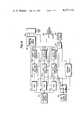
- FIG. 4is a block diagram of the conversion apparatus in accordance with the present invention.
- FIG. 5illustrates the eight pixels forming a neighbor field surrounding a typical pixel in a video display
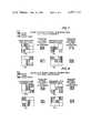
- FIG. 6illustrates the conversion table or scheme for enhancing a particular pixel
- FIG. 7illustrates the 90° rotation of a neighboring field
- FIG. 8illustrates mirror images of a typical neighboring field.
- the letter "R”is shown represented in a rectilinear form as it commonly appears on a video display and provided at the output of a computer or display terminal.
- the characteris formed from a number of adjacent sectors corresponding to pixels on a video display.
- a typical sector in FIG. 1is designated as 45 (row 4, column 5). Each sector is either “solid” or not, in accordance with whether the corresponding pixel element in "on” or "off”.
- This digital format or video signalrepresents a line-by-line scan of an image field.
- each information bit in the video signalrepresents the presence or absence of a pixel (picture element) at each point in the field, and thus represents the image to be reproduced.
- the imageis effectively divided into a number of sectors, preferably one sector for each pixel.
- each sectorin accordance with the present invention, the status of each "nearest neighbor" is examined for the presence or absence of a pixel.
- the eight surrounding pixels or nearest neighbors for a particular pixelis called a neighboring field.
- the result of this examination of the neighboring fieldis to produce an identifier which uniquely represents an enhanced status of each pixel or sector as shown in FIGS. 2 and 3. This identifier is then applied to a decoder which provides enhanced sector data as an output to a printing head.
- each pixel or sectoris converted to a 3 ⁇ 3 enhancement.
- the on-off status of each element of the 3 ⁇ 3 enhancement of a particular pixelis determined by the initial examination of the neighboring field of that particular pixel.
- the enhanced sector datatypically comprises a sector of increased point density, with certain of the points deleted or added, as appropriate, to form a rounded, diagonal or other desired curvilinear shape.
- the output datais then printed by conventional printing means in a conventional manner.
- the image enhancer or conversion procedureexamines each sector of the neighboring field of a particular sector or pixel and forms the unique identifier for enhancing that particular pixel.
- the image enhancerexamines the sectors 35 and 55 immediately above and below it, the sectors 44 and 46 immediately to the left and to the right of it and the sectors 34, 36, 54, 56 diagonally adjacent to it.
- the identifier formed as a result of this examinationdetermines whether the sector 45 as finally reproduced will correspond precisely with the sector as originally presented or will, instead, be modified to enhance the sector as originally presented.
- each sector of FIG. 1has been subdivided into a 3 ⁇ 3 matrix of subsectors.
- the character in FIG. 2has three times the pixel density or resolution of the character R in FIG. 1.
- the character Ris illustrated as white whereas as actually printed, the character will be black.
- Each of these subsectorscan be modified to enhance the original sector.
- the lower right subsector of sector 45is off or white while the remaining eight subsectors remain on or black. The effect is to smooth a portion of the character R.
- Other sectorsare similarly enhanced. For example, sector 35 immediately above the sector 45, in the enhanced form, will have a portion "filled in", despite the fact that the original was blank.
- the image enhancer of the present inventioncan both fill in (sector 35) and remove (sector 45) portions of sectors in the final image in order to improve the quality of the original image.
- the enhancement procedureoperates in the following manner.
- the systemscans across each line of raster data and for each pixel determines a 3 ⁇ 3 subpixel enhancement of that pixel. It does this by examining the 8 neighboring pixels A, B, C, D, E, F, G and H, in the original unenhanced image as shown in FIG. 5. To do this, three successive lines (line 1, line 3 and the intermediate line containing the pixel to be enhanced) of raster data must be available simultaneously, with the pixel information (black or white) synchronized in time as with the original image. The system thus looks at a field of 9 pixels, the central pixel being the sector to be enhanced. The 8 surrounding pixels are in the exact same physical orientation as they would be seen in the unenhanced image.
- the neighbor fieldincrements along each raster line. That is, the sector to the right of the central pixel next becomes the central pixel and the previous central pixel becomes a neighbor field sector.
- a complete neighbor fieldis lacking such as in the first raster line, or at the edge pixel in a line, the missing sectors or pixels are considered white.
- the neighbor fieldmoves down one line.
- the enhancement of the central pixelis done either by directly addressing a 9 bit table location and reading out 9 bits of data which corresponds to the 3X enhancement in each dimension or by performing a table search.
- the table searchcan be performed by progressively examining an ordered table of matches to find an equivalent images and its related enhancement.
- a table of patternsis shown in FIG. 6.
- each entryhas each of the 9 pixels in the unenhanced neighbor field either on (vertical cross-hatch representing black) or off (white) or does not matter (horizontal cross hatch).
- the table fieldmust have exactly the same kind of pixels as the field being enhanced. In some cases, certain pixels can be either on or off and still constitute a match, but the pixels on and off must be in exactly the same position in the table field as the initial image field or its rotated or mirrored equivalents illustrated in FIGS. 8 and 9 by patterns 13 through 20. Once a match is found, the appropriate symmetrical enhancement is used for the central pixel.
- patterns 1 through 20are merely illustrative to produce a particular enhanced image.
- Other enhancement techniquesare easily obtainable from the teaching of this invention.
- Other enhancement techniquescould provide for example a different image font, a different degree of image manipulation, or a different degree of image resolution enhancement.
- the procedureis generally as follows. Each raster line of the input image is scanned through three times before the row is incremented. Each successive scan of the same line produces a new raster line of subpixels for the enhanced pixel. For example, the first scan of a line of the image produces the three top subpixels of the enhanced image. The second scan of the same line produces the middle three subpixles of the enhanced image and the third scan produces the bottom three subpixels. In other words, each pixel of the original image line is converted into a 3 ⁇ 3 matrix of subpixels.
- each unenhanced 9 bit pixel setis mapped into a 9 bit enhancement of the central pixel of the unenhanced set.
- FIG. 6list twelve basic unenhanced pixel neighbor field patterns and the associated central pixel after enhancement.
- Each of the pixels in a patternis represented as either black, by vertical cross-hatching, white or by a horizontal cross-hatched pattern.
- the horizontal cross-hatched patternmeans that the pixel can either be black or white and does not affect the resulting enhanced center pixel.
- Pattern 1 in FIG. 6shows four black pixels, three white pixels and two horizontal cross-hatched pixels.
- the resulting enhanced center pixelshows an almost completely black center pixel with one white subpixel in the lower righthand corner.
- Patterns 2, 3 and 5show variations having four dark sectors, three white sectors and two horizontal cross-hatched sectors, with the resultant center pixel having the same pattern, black with only a white subpixel in the lower righthand corner.
- the pattern as shown in 4results in an enhanced pixel having a white subpixel in both the upper left and lower righthand corners
- the pattern in 6results in an enhanced pixel having white subpixels in the lower left and lower righthand corners.
- Pattern 7is similar to pattern 4 except the lower lefthand neighbor sector can be either white or black.
- the patterns 9, 10 and 11will result in the enhanced pixel as shown corresponding to those three patterns.
- Pattern 8has a dark center pixel and the remaining neighbor sectors represented as being either on or off.
- the resulting enhanced pixelwill be a completely black center pixel. However, it should be understood that this is a default case and the resulting pixel will only occur in the case of pattern 8 if no other match is found. That is, if the pattern 8 is not identical to patterns 1-7, or as will be seen, a rotation or mirror image of these patterns, then the resultant pixel will be as shown for pattern 8.
- Pattern 12has a white center pixel is also a default case. That is, if the pattern does not match any of the patterns 1-7, or 9, 10 or 11, or rotations or mirror images thereof, and the pattern has a white center pixel, then the resultant pixel will be completely white.
- patterns 13, 14, 15 and 16These patterns are the same as pattern 1 except that the horizontal cross-hatched subpixels shown in pattern 1 are white in patterns 13-16. These patterns illustrate the 90° rotation of pattern 1. As shown in FIG. 7, the resulting enhanced pixel shows a white subpixel successively in lefthand lower righthand corner, the upper righthand corner, the upper lefhand corner, and the lower lefthand corner. In operation, each table entry is rotated 90° to see if any of the rotated patterns correspond to the unenhanced neighbor field being examined. These rotated patterns will result in the corresponding enhanced central pixel if a match is found.
- patterns 17, 18, 19 and 20illustrate mirror images of patterns 13, 14, 15 and 16.
- the resultant enhanced pixelsare the mirror image of the resultant subpixels of patterns 13, 14, 15 and 16.
- the resultant enhanced pixel of pattern 17is a white subpixel in the lower lefthand corner
- the resultant pixel for pattern 18is a white subpixel in the upper lefthand corner
- for pattern 19a white subpixel in the upper righthand corner
- for pattern 20a white subpixel in the lower righthand corner.
- the patterns 17, 18, 19 and 20are also searched for a match with the original unenhanced pixel and neighbor field.
- FIG. 4Apparatus for performing the image enhancement in accordance with the present invention is shown in FIG. 4.
- a composite video decoder 30strips the horizontal and vertical synchronizing signals from applied video data.
- the decoder 30transmits these signals to line selectors 34, 36 and 38.
- the two-to-one line selectors 34, 36, 38receive second inputs from three-bit shift registers 40, 42 and 44.
- the outputs of line selectors 34, 36, 38are applied to shift registers 46, 48 and 50, respectively.
- the registers 46, 48, 50are, for example, 477-bit shift registers to accommodate one video scan line each.
- Register 48receives the scan line containing the center pixel to be enhanced.
- Register 46receives the image line above the center pixel and register 50 receives the scan line below the center pixel.
- One by three shift registers 40, 42, 44receive the outputs of registers 46, 48, 50 three bits at a time, and, in turn, apply their outputs (3 bits) to a decoder 52.
- the decoder 52receives the 3 ⁇ 3 bit matrix array corresponding the unenhanced center pixel and 8 neighboring sectors.
- Shift register 40provides the top 3 neighboring sectors
- register 42provides the center pixel and two neighbors from the image line to be enhanced
- register 44provides the bottom three neighboring sectors.
- the output of decoder 52comprises three successive three-bit strings of data applied to a reproducing head through a three-bit shift register 54.
- a counter 56provides the appropriate incrementing drives for the head location, while clocks 58 and 60, data selector 62, and counter 64 provide appropriate timing signals for advancing the data bits through the shift registers 40, 42, 44, 46, 48 and 50.
- the decoder or logic array 52maps each unenhanced 9 bit pixel set provided by registers 40, 42 and 44 into the 9 pixel enhancement of the central pixel.
- an algorithmas illustrated in Appendix I, compares the unenhanced 9 bit pixel set with the table of patterns as illustrated in FIGS. 6, 7, and 8 to provide an identifier which uniquely describes the status of each neighboring sector of the center pixel. Depending upon this identified decoder 52 produces the corresponding 9 bit enhancement of the central pixel.
- the decoder 30As each line of video data is applied to the decoder 30, it is routed through one of the data selectors 34, 36, 38 to one of the corresponding shift registers 46, 48, 50. At any given time, therefore, the shift registers 46, 48, 50 will contain successive lines of video data.
- the outputs of the three bit registers 40, 42, 44 at a given timecomprises a 3 ⁇ 3 matrix so that information concerning the central pixel in a given middle line is provided. In other words, successive outputs from the registers 40, 42, 44 provide the neighbors field or 8 surrounding bits of the center pixel provided by register 42. This information forms the "identifier" or "address" which is compared to the table of patterns and applied to decoder 52 to generate the required sectors for the enhanced image. In the present case, for each sector or pixel in the original image, a 3 ⁇ 3 matrix of sectors are formed in the enhanced image.
- registers 46, 48 and 50may be desirable to add other shift registers of equivalent function to registers 46, 48 and 50 to buffer succeeding raster lines and further decouple the printing means timing from the input raster timing.
Landscapes
- Engineering & Computer Science (AREA)
- General Engineering & Computer Science (AREA)
- Physics & Mathematics (AREA)
- General Physics & Mathematics (AREA)
- Theoretical Computer Science (AREA)
- Controls And Circuits For Display Device (AREA)
Abstract
Description
__________________________________________________________________________APPENDIX I __________________________________________________________________________C+ C CSMOOT-SMOOTH A CHARACTER-MAIN ROUTINE C- C PROGRAM CSMOOT C C INCLUDE `CSMDEF.INC` C C TYPE*, `ENTER HIT DETAIL FILE NAME [CR=NONE]` ACCEPT 1,CTEMP 1 FORMAT (A32) IF(CTEMP.NE` `) THEN !IF WANT TEXT OUT DTLUNT=DTLUVL OPEN(UNIT=DTLUNT,STATUS=`NEW`,NAME=CTEMP,ERR=900) END IF !END IF C C TYPE*,`ENTER TEXT PLOT FILE NAME` ACCEPT 2,CTEMP 2 FORMAT(A32) IF (CTEMP.NE.` `) THEN !IF WANT TEXT OUT TXTUNT=DXTUVL OPEN(UNIT=TXTUNT,STATUS=`NEW`,NAME=CTEMP,ERR=900 END IF !END IF C C PLTFLG=.FALSE. !SET NO PLOTS TYPE*,`WANT GOULD PLOTS` ACCEPT 4,CTEMP 4 FORMAT(A1) IF (CTEMP.EQ.`Y`) PLTFLG=.TRUE. !IF YES GET THEM C TYPE*,`ENTER CHARACTER DATA FILE NAME` ACCEPT 3,CTEMP 3 FORMAT (A32) BCDUNT=BCDUVL OPEN (UNIT=BCDUNT,STATUS=`OLD`,NAME=CTEMP,ERR=900) C C CALL CSMLXT(TBA,TPA,TLTCNT,TLTUNT) !LOAD TRANSLATION ARRAYS IF (PLTFLG) CALL PLOTS(16.,21.) ! SET PLOTTING IF (PLTFLG) CALL FACTOR (2.)C C 10 CONTINUE !LOOP TYPE*,`NEXT CHARACTER [YES, NO,EXIT]` ACCEPT 1,CTEMP IF (CTEMP.EQ.`E`)GOTO 20 !EXITIF EXIT CALL CSMGTC (BA10,SUC,BCDUNT) !GET A CHARACTER IF (SUC.EQ..FALSE.) GOTO 20 !EXITIF NO MORE IF (CTEMP.EQ.`Y`) THEN !IF WANT TO DO IT DO 15 Y10=1,10 !LOOP ON BA10 DO 15 X10=1,10 DO 15 Y3=1,3 DO 15 X3=1,3 PA30(X10-1)*3+X3,(Y10-1)*3+Y3)=BA10(X10,Y10) 15 CONTINUE !END LOOP BA10=PA30 IF (PLTFLG) CALL GNRTE (PA30) !PLOT OUT BLOCKY CALL CSMPRT (PA30, TXTUNT) !PRINT IT CALL CSMWRK (BA10,PA30,TBA,TPA,TLTCNT,DTLUNT) !SMOOTH IT CALL CSMPRT (PA30, TXTUNT) !PRINT IT IF (PLTFLG) CALL GNRTE (PA30) !PLOT OUT SMOOTHED END IF !END IF GOTO 10 20 CONTINUE !END LOOP C C IF (PLTFLG) CALL PLOT(0.,0.,999) !TERMINATE PLOT C STOP C C 900 STOP `ERROR OPENING FILE` END C+ C CSMSMT-GENERATE A 3 BY 3 SMOOTHED PIXEL ARRAY FROM A 3 BY 3 BLOCK ARRAY C THE TRANSLATION ARRAY IS ASSUMED TO HOLD ALL NECESSARY ROTATIONS C C INPUTS-BA3-THE 3 BY 3 BLOCK ARRAY TBA,TPA,TLTCNT-THE TRANSITION ARRAYS AND COUNT DTLUNT-DETAILS C C OUTPUTS-PA3-THE 3 BY 3 PIXEL ARRAY C- C C SUBROUTINE CSMSMT(BA3,PA3,TBA,TPA,TLTCNT,DTLUNT) C C INCLUDE `CSMDEF.INC` C C INTEGER*4 TRIDX !INDEX INTO TRANSLATION TABLES C C D WRITE(DRGUNT,*) `BA3 AT ENTRY TO CSMSMT` D WRITE(DBGUNT,1)BA3 D1 FORMAT(` `,313/) C C DO 30, TRIDX=1,TLTCNT !LOOP ON ALL TRANSLATIONS SUC=.TRUE. !SET GOOD DO 10, Y3=1,3 !LOOP ON THE INPUT DATA DO 10, X3=1,3 IF(TBA(X3,(((TRIDX-1)*3)+Y3)).NE.-1. AND. . TBA(X3,(((TRIDX-1)*3)+Y3)).NE. . BA3(X3,Y3)) SUC=.FALSE. !SET BAD IF NO MATCH !(-1)=NO-CARE IF(SUC.EQ..FALSE.)GOTO 20 !EXITIF NO MATCH 10 CONTINUE !END DO 20 CONTINUE !END LOOP IF (SUC.EQ..TRUE.)GOTO 40 !EXITIFFOUND A MATCH 30 CONTINUE !END DO 40 CONTINUE !END LOOP C C IF(SUC.NE..TRUE.)STOP `NO MATCH FOUND IN CSMSMT` C C IF(DTLUNT.NE.0) THEN !IF WANT DETAILS WRITE(DTLUNT,*)`FOUND XLATION ENTRY #`, TRIDX, TRIDX/4. END IF !END IF DO 50, Y3=1,3 !LOOP ON PIXEL ARRAY DO 50, X3=1,3 PA3(X3,Y3)=TPA(X3,(((TRIDX-1)*3)+Y3)) !MOVE SMOOTHED STUFF 50 CONTINUE !END LOOP ON PIXEL ARRAY C C D WRITE(DBGUNT,*)`PA3 AT EXIT FROM CSMSMT` D WRITE(DBGUNT,31)PA3 D31 FORMAT(` `,313/) RETURN END C+ C CSMWRK-GIVEN A 10 BY 10 BLOCK CHARACTER GENERATE A 30 BY 30 PIXEL C CHARACTER C C INPUTS-BA10-THE BLOCK CHARACTER DTLUNT-THE DETAIL UNIT(0=NONE) C C OUTPUTS-PA30-THE PIXEL ARRAY C C- C C SUBROUTINE CSMWRK(BA10,PA30,TBA,TPA,TLTCNT,DTLUNT) C C INCLUDE `CSRDEF.INC` C C BYTE BWA(12,12) !DEFINE BLOCK WORK ARRAY C C DO 10 Y10=1,10 !LOOP ON CHARACTER BLOCK DO 10 X10=1,10 BWA(X10+1,Y10+1)=BA10(X10,Y10) !PUT WORK ARRAY WITH 1 !SPACE ON EACH EDGE 10 CONTINUE !END LOOP DO 40 Y10=1,10 !LOOP AND PASS 3 BY 3 OVER WORK DO 40 X10=1,10 C C DO 20 Y3=1,3 !LOOP ON 3 BY 3 BLOCK DO 20 X3=1,3 BA3(X3,Y3)=BWA(X10+X3- 1,Y10+Y3-1) !LOAD UP A 3 BY 3 BLOCK 20 CONTINUE !END LOOP LOAD CALL CSMSMT (BA3,PA3,TBA,TPA,TLTCNT,DTLUNT) !GET SMOOTHED VERSION IF (DTLUNT.NE.0) THEN !IF WANT DETAILS WRITE (DTLUNT,*)`OF BLOCK`,X10,Y10 WRITE (DTLUNT,21) BA3,PA3 21 FORMAT (`0`,3(313/)) END IF !FI DO 30 Y=1,3 !LOOP ON PIXELS DO 30 X=1,3 PA30((((X10-1)*3)+X),(((Y10-1)*3)+Y))= !ZAP IN PIXEL ARRAY . PA3(X,Y) 30 CONTINUE !END LOOP ONPIXELS 40 CONTINUE !END LOOP ON CHARACTER C C D WRITE (DBGUNT,*)`PA30 ON EXIT FROM CSMWRK` D WRITE (DBGUNT,41) PA30 D41 FORMAT (` `,30II) RETURN END __________________________________________________________________________
Claims (27)
Priority Applications (1)
| Application Number | Priority Date | Filing Date | Title |
|---|---|---|---|
| US06/303,742US4437122A (en) | 1981-09-12 | 1981-09-12 | Low resolution raster images |
Applications Claiming Priority (1)
| Application Number | Priority Date | Filing Date | Title |
|---|---|---|---|
| US06/303,742US4437122A (en) | 1981-09-12 | 1981-09-12 | Low resolution raster images |
Publications (2)
| Publication Number | Publication Date |
|---|---|
| US4437122Atrue US4437122A (en) | 1984-03-13 |
| US4437122B1 US4437122B1 (en) | 1993-03-30 |
Family
ID=23173493
Family Applications (1)
| Application Number | Title | Priority Date | Filing Date |
|---|---|---|---|
| US06/303,742Expired - LifetimeUS4437122A (en) | 1981-09-12 | 1981-09-12 | Low resolution raster images |
Country Status (1)
| Country | Link |
|---|---|
| US (1) | US4437122A (en) |
Cited By (177)
| Publication number | Priority date | Publication date | Assignee | Title |
|---|---|---|---|---|
| US4521812A (en)* | 1981-10-19 | 1985-06-04 | Dr.-Ing. Rudolf Hell Gmbh | Method of improving contrast accentuation |
| US4571635A (en)* | 1984-02-17 | 1986-02-18 | Minnesota Mining And Manufacturing Company | Method of image enhancement by raster scanning |
| EP0162259A3 (en)* | 1984-05-17 | 1986-06-25 | International Business Machines Corporation | Interacting print enhancement techniques |
| US4682301A (en)* | 1982-09-02 | 1987-07-21 | Hitachi Medical Corp. | Digital filter for processing two-dimensional digital image |
| DE3602043A1 (en)* | 1986-01-24 | 1987-07-30 | Siemens Ag | METHOD FOR INCREASING THE VERTICAL RESOLUTION OF DOCUMENTS |
| US4703363A (en)* | 1983-11-10 | 1987-10-27 | Dainippon Screen Mfg. Co., Ltd. | Apparatus for smoothing jagged border lines |
| US4713779A (en)* | 1985-03-08 | 1987-12-15 | Ing.C. Olivetti & Co. S.P.A. | Video converter |
| US4720745A (en)* | 1983-06-22 | 1988-01-19 | Digivision, Inc. | Method and apparatus for enhancing video displays |
| US4771471A (en)* | 1985-03-07 | 1988-09-13 | Dainippon Screen Mfg. Co., Ltd. | Smoothing method for binary-coded image data and apparatus therefor |
| US4791679A (en)* | 1987-12-26 | 1988-12-13 | Eastman Kodak Company | Image character enhancement using a stroke strengthening kernal |
| US4806759A (en)* | 1985-10-09 | 1989-02-21 | Fuji Photo Film Co., Ltd. | Method of adjusting radiation image read-out conditions |
| US4849821A (en)* | 1987-12-11 | 1989-07-18 | Eastman Kodak Company | Page check for copier/printers |
| US4853794A (en)* | 1986-12-01 | 1989-08-01 | Sakata Inkusu Kabushikikaisha | Method and image processing system for reconstruction of an image |
| EP0331033A3 (en)* | 1988-02-29 | 1989-10-18 | Oki Electric Industry Company, Limited | Printing system for dot-matrix printer |
| US4893188A (en)* | 1987-06-19 | 1990-01-09 | Hitachi, Ltd. | Document image entry system |
| US4894794A (en)* | 1985-10-15 | 1990-01-16 | Polaroid Corporation | System for providing continous linear interpolation |
| US4907152A (en)* | 1986-09-25 | 1990-03-06 | The Boeing Company | Method of improving CT resolution |
| US4967211A (en)* | 1988-06-14 | 1990-10-30 | International Business Machines Corporation | Printing machine with toner density balance in solid areas and line strokes |
| US4975785A (en)* | 1989-08-04 | 1990-12-04 | International Business Machines Corporation | Pel resolution addressing conversion |
| US4977602A (en)* | 1989-11-20 | 1990-12-11 | Eastman Kodak Company | Character normalization using an elliptical sampling window for optical character recognition |
| US5006937A (en)* | 1985-12-06 | 1991-04-09 | Canon Kabushiki Kaisha | Imaging data processing apparatus |
| US5128698A (en)* | 1990-01-19 | 1992-07-07 | International Business Machines Corporation | Boldness control in an electrophotographic machine |
| US5134495A (en)* | 1990-11-07 | 1992-07-28 | Dp-Tek, Inc. | Resolution transforming raster-based imaging system |
| US5140350A (en)* | 1989-05-30 | 1992-08-18 | Minolta Camera Kabushiki Kaisha | Image forming apparatus for forming an image with smooth curved lines |
| EP0488534A3 (en)* | 1990-11-26 | 1992-11-25 | Canon Kabushiki Kaisha | Outputting method and apparatus |
| US5193008A (en)* | 1990-11-07 | 1993-03-09 | Dp-Tek, Inc. | Interleaving vertical pixels in raster-based laser printers |
| EP0488118A3 (en)* | 1990-11-26 | 1993-03-24 | Sharp Kabushiki Kaisha | Image recording apparatus for high quality images |
| EP0473142A3 (en)* | 1990-08-28 | 1993-04-14 | Kyocera Corporation | Method for smoothing an image |
| EP0506381A3 (en)* | 1991-03-28 | 1993-05-05 | Canon Kabushiki Kaisha | Image processing apparatus |
| EP0506483A3 (en)* | 1991-03-29 | 1993-05-05 | Canon Kabushiki Kaisha | Information recording apparatus and image recording method |
| EP0500375A3 (en)* | 1991-02-22 | 1993-05-26 | Canon Kabushiki Kaisha | Information recording apparatus |
| EP0484919A3 (en)* | 1990-11-06 | 1993-06-09 | Oki Electric Industry Co., Ltd. | Printer having print data arithmetic logic |
| US5231519A (en)* | 1990-11-20 | 1993-07-27 | Ricoh Company, Ltd. | Image processor which converts image with poor resolution into image with improved resolution |
| EP0526738A3 (en)* | 1991-07-05 | 1993-08-11 | Oki Electric Industry Co., Ltd. | Printer having print data correction circuit |
| EP0555064A1 (en)* | 1992-02-04 | 1993-08-11 | Canon Kabushiki Kaisha | Image processing apparatus and recording apparatus |
| US5237646A (en)* | 1992-10-13 | 1993-08-17 | Hewlett-Packard Company | Pixel image enhancement employing a reduced template memory store |
| EP0495462A3 (en)* | 1991-01-14 | 1993-09-22 | Seiko Epson Corporation | Method for generating bit map image data and a method and apparatus for modulating a laser beam with same |
| US5283557A (en)* | 1991-07-05 | 1994-02-01 | Ncr Corporation | Method for converting high resolution data into lower resolution data |
| EP0582369A1 (en)* | 1992-05-28 | 1994-02-09 | Xerox Corporation | Bit-map image resolution converter with controlled compensation for write-white xerographic laser printer |
| EP0584966A1 (en)* | 1992-08-26 | 1994-03-02 | Hewlett-Packard Company | Pixel image edge-smoothing method and system |
| US5293254A (en)* | 1991-12-06 | 1994-03-08 | Xerox Corporation | Method for maintaining bit density while converting images in scale or resolution |
| EP0583873A3 (en)* | 1992-06-30 | 1994-06-08 | Canon Kk | Information recording apparatus |
| EP0601735A1 (en)* | 1992-11-25 | 1994-06-15 | Xerox Corporation | Resolution conversion with simulated multi-bit gray |
| US5329599A (en)* | 1991-12-20 | 1994-07-12 | Xerox Corporation | Enhanced fidelity reproduction of images by hierarchical template matching |
| US5341153A (en)* | 1988-06-13 | 1994-08-23 | International Business Machines Corporation | Method of and apparatus for displaying a multicolor image |
| US5357273A (en)* | 1991-07-29 | 1994-10-18 | Xerox Corporation | Resolution conversion via intensity controlled overscanned illumination for optical printers and the like having high gamma photosensitive recording media |
| US5359423A (en)* | 1993-12-17 | 1994-10-25 | Xerox Corporation | Method for statistical generation of density preserving templates for print enhancement |
| US5365251A (en)* | 1992-08-28 | 1994-11-15 | Xerox Corporation | Image quality improvement by hierarchical pattern matching with variable size templates |
| US5367381A (en)* | 1991-07-29 | 1994-11-22 | Xerox Corporation | Method and apparatus for enhanced resolution and contrast via super intensity controlled overscanned illumination in a two dimensional high addressability printer |
| US5383036A (en)* | 1993-09-29 | 1995-01-17 | Xerox Corporation | Enhancement of multiple color images without color separation error by inverse symmetrical template matching |
| US5387985A (en)* | 1993-12-17 | 1995-02-07 | Xerox Corporation | Non-integer image resolution conversion using statistically generated look-up tables |
| US5404411A (en)* | 1990-12-27 | 1995-04-04 | Xerox Corporation | Bitmap-image pattern matching apparatus for correcting bitmap errors in a printing system |
| US5408329A (en)* | 1992-09-08 | 1995-04-18 | Xerox Corporation | Image enhancement through digital darkness control |
| US5410614A (en)* | 1993-10-22 | 1995-04-25 | Industrial Technology Research Institute | Run-based method for smoothing handwritten Chinese characters |
| US5424845A (en)* | 1993-02-25 | 1995-06-13 | Ohio Electronic Engravers, Inc. | Apparatus and method for engraving a gravure printing cylinder |
| US5430472A (en)* | 1991-07-29 | 1995-07-04 | Xerox Corporation | Method and apparatus for eliminating distortion via overscanned illumination for optical printers and the like having high gamma photosensitive recording media and high addressability |
| US5438422A (en)* | 1993-02-25 | 1995-08-01 | Ohio Electronic Engravers, Inc. | Error detection apparatus and method for use with engravers |
| US5440398A (en)* | 1993-02-25 | 1995-08-08 | Ohio Electronic Engravers, Inc. | Error detection apparatus and method for use with engravers |
| US5440407A (en)* | 1994-03-11 | 1995-08-08 | Hewlett-Packard Company | Pixel correction and smoothing method |
| US5450208A (en)* | 1992-11-30 | 1995-09-12 | Matsushita Electric Industrial Co., Ltd. | Image processing method and image processing apparatus |
| US5479584A (en)* | 1992-08-28 | 1995-12-26 | Xerox Corporation | Enhanced fidelity reproduction of images with device independent numerical sample output |
| US5479175A (en)* | 1993-09-10 | 1995-12-26 | Xerox Corporation | Method and apparatus for enhancing discharged area developed regions in a tri-level pringing system |
| US5483355A (en)* | 1994-03-11 | 1996-01-09 | Hewlett-Packard Co. | Pixel correctional and smoothing method |
| US5483351A (en)* | 1992-09-25 | 1996-01-09 | Xerox Corporation | Dilation of images without resolution conversion to compensate for printer characteristics |
| US5485289A (en)* | 1993-10-28 | 1996-01-16 | Xerox Corporation | Hyperacuity printer architecture |
| DE19506791C1 (en)* | 1995-02-27 | 1996-02-15 | Siemens Nixdorf Inf Syst | Print quality improving apparatus for high speed printer |
| EP0708415A2 (en) | 1994-10-18 | 1996-04-24 | Hewlett-Packard Company | Four-quadrant scaling of dot matrix data |
| US5516216A (en)* | 1993-04-30 | 1996-05-14 | Hewlett-Packard Company | Print enhancement system for enhancing dot printer images |
| WO1996017469A1 (en)* | 1994-12-02 | 1996-06-06 | Comsat Corporation | Methods performing 2-dimensional maximum differences coding and decoding during real-time facsimile image compression and apparatus |
| US5526468A (en)* | 1995-03-27 | 1996-06-11 | Lexmark International, Inc. | Method and apparatus for smoothing an expanded bitmap for two-state image data |
| US5528296A (en)* | 1993-11-02 | 1996-06-18 | Texas Instruments Incorporated | Jagged edge compensator for staggered pixel layouts of a spatial light modulator |
| US5535307A (en)* | 1994-08-16 | 1996-07-09 | Hewlett-Packard Company | Printing of variable dot sizes dependent upon image density for improved graphics |
| EP0720919A1 (en) | 1995-01-03 | 1996-07-10 | Xerox Corporation | Resolution enhancement and thinning method for printing pixel images |
| US5537515A (en)* | 1991-01-14 | 1996-07-16 | Seiko Epson Corporation | Method and apparatus for generating bit map image data |
| US5537495A (en)* | 1994-03-11 | 1996-07-16 | Hewlett-Packard Company | Pixel correction and smoothing method |
| US5539866A (en)* | 1994-05-11 | 1996-07-23 | Xerox Corporation | Method and apparatus for accurately rendering half-bitted image pixels |
| DE19506792A1 (en)* | 1995-02-27 | 1996-09-05 | Siemens Nixdorf Inf Syst | Image quality improving method for image output devices |
| US5572606A (en)* | 1985-10-18 | 1996-11-05 | Canon Kabushiki Kaisha | Image information processing method and apparatus therefor with multi-level data capability |
| US5574833A (en)* | 1992-09-02 | 1996-11-12 | Ricoh Company, Ltd. | Image processing apparatus for the smooth enlargement and multileveling output of an image |
| US5579445A (en)* | 1993-12-17 | 1996-11-26 | Xerox Corporation | Image resolution conversion method that employs statistically generated multiple morphological filters |
| US5581292A (en)* | 1993-09-10 | 1996-12-03 | Xerox Corporation | Method and apparatus for enhancing charged area developed regions in a tri-level printing system |
| US5611023A (en)* | 1992-09-02 | 1997-03-11 | Ricoh Company, Ltd. | Apparatus and method for processing two-tone image data so as to smooth and magnify image |
| US5617217A (en)* | 1993-02-25 | 1997-04-01 | Ohio Electronic Engravers, Inc. | Engraving method and apparatus for generating engraving drive signals for engraving engraved areas of accurately controlled size in the surface of a workpiece using coefficient values and associated set up parameter values |
| US5657430A (en)* | 1996-03-07 | 1997-08-12 | Hewlett-Packard Company | Software-based procedure for conversion of a scalable font character bitmap to a gray level bitmap |
| US5664070A (en)* | 1990-03-30 | 1997-09-02 | Canon Kabushiki Kaisha | Outputting method and apparatus |
| US5671063A (en)* | 1993-02-25 | 1997-09-23 | Ohio Electronic Engravers, Inc. | Error tolerant method and system for measuring features of engraved areas |
| US5677714A (en)* | 1995-01-03 | 1997-10-14 | Xerox Corporation | Neighbor insentive pixel deletion method for printing high resolution image |
| US5680485A (en)* | 1994-12-19 | 1997-10-21 | Xerox Corporation | Method and apparatus employing erosion-based filter pairs for image mapping |
| US5696845A (en)* | 1993-12-17 | 1997-12-09 | Xerox Corporation | Method for design and implementation of an image resolution enhancement system that employs statistically generated look-up tables |
| US5708919A (en)* | 1995-05-02 | 1998-01-13 | Minolta Co., Ltd. | Imaging forming apparatus for forming images on both surfaces of recording medium |
| US5714974A (en)* | 1992-02-14 | 1998-02-03 | Industrial Technology Research Laboratories | Dithering method and circuit using dithering matrix rotation |
| US5719967A (en)* | 1994-07-07 | 1998-02-17 | Fuji Xerox Co., Ltd. | Iimage processing apparatus |
| US5719601A (en)* | 1995-01-03 | 1998-02-17 | Xerox Corporation | Intentional underthinning of 600×300 image data when printing in multi-pass mode |
| US5719595A (en)* | 1995-05-09 | 1998-02-17 | Apple Computer, Inc. | Method and apparauts for generating a text image on a display with anti-aliasing effect |
| US5724455A (en)* | 1993-12-17 | 1998-03-03 | Xerox Corporation | Automated template design method for print enhancement |
| US5729634A (en)* | 1996-03-29 | 1998-03-17 | Xerox Corporation | Document processing system for enhancing halftone images including multiple centered dots |
| US5737090A (en)* | 1993-02-25 | 1998-04-07 | Ohio Electronic Engravers, Inc. | System and method for focusing, imaging and measuring areas on a workpiece engraved by an engraver |
| US5742703A (en)* | 1995-10-11 | 1998-04-21 | Xerox Corporation | Method and apparatus for the resolution enhancement of gray-scale images that include text and line art |
| US5754751A (en)* | 1996-03-07 | 1998-05-19 | Hewlett-Packard Company | Software-based procedure and apparatus for enhancement of a gray level image |
| US5758034A (en)* | 1996-09-26 | 1998-05-26 | Xerox Corporation | Video path architecture including logic filters for resolution conversion of digital images |
| US5767870A (en)* | 1995-01-03 | 1998-06-16 | Xerox Corporation | Edge insensitive pixel deletion method for printing high resolution image |
| US5768569A (en)* | 1995-05-09 | 1998-06-16 | Apple Computer, Inc. | Processing data for an image displayed on a computer controlled display system |
| US5805304A (en)* | 1994-09-01 | 1998-09-08 | Fuji Xerox Co., Ltd. | Image processing apparatus |
| US5815605A (en)* | 1992-07-17 | 1998-09-29 | Ricoh Company, Ltd. | Image processing system and method |
| US5818502A (en)* | 1995-03-03 | 1998-10-06 | Fujitsu Limited | Imaging forming apparatus with smoothing circuitry |
| US5825503A (en)* | 1993-02-25 | 1998-10-20 | Ohio Electronic Engravers, Inc. | Engraving apparatus and method for adjusting a worn stylus using a midtone correction |
| US5831746A (en)* | 1993-02-25 | 1998-11-03 | Ohio Electronic Engravers, Inc. | Engraved area volume measurement system and method using pixel data |
| US5862305A (en)* | 1996-09-26 | 1999-01-19 | Xerox Corporation | Logic filters for resolution conversion of digital images |
| US5875268A (en)* | 1993-09-27 | 1999-02-23 | Canon Kabushiki Kaisha | Image processing with low-resolution to high-resolution conversion |
| US5920336A (en)* | 1995-09-12 | 1999-07-06 | Hewlett-Packard Company | Beam deflecting for resolution enhancement and banding reduction in a laser printer |
| US5940190A (en)* | 1993-08-23 | 1999-08-17 | Lexmark International, Inc. | Image improvement after facsimile reception |
| US5956470A (en)* | 1997-09-25 | 1999-09-21 | Xerox Corporation | Text quality enhancement via resolution enhancement technique based on separating jaggedness detection and filtering |
| EP0855671A3 (en)* | 1997-01-27 | 1999-09-22 | Canon Kabushiki Kaisha | Image processing method and apparatus, and image forming apparatus |
| US5966475A (en)* | 1997-02-20 | 1999-10-12 | Hewlett-Packard Company | System for enlarging and smoothing textual characters |
| US5999273A (en)* | 1992-09-08 | 1999-12-07 | Xerox Corporation | Solid area toner reduction to maximize process latitude |
| US6012070A (en)* | 1996-11-15 | 2000-01-04 | Moore Business Forms, Inc. | Digital design station procedure |
| US6016154A (en)* | 1991-07-10 | 2000-01-18 | Fujitsu Limited | Image forming apparatus |
| US6038348A (en)* | 1996-07-24 | 2000-03-14 | Oak Technology, Inc. | Pixel image enhancement system and method |
| JP3021806B2 (en) | 1991-06-29 | 2000-03-15 | ミノルタ株式会社 | Image generator |
| US6067102A (en)* | 1995-04-26 | 2000-05-23 | Hitachi, Ltd. | Electrophotographic recording device and exposure controlling device therefor |
| US6075926A (en)* | 1997-04-21 | 2000-06-13 | Hewlett-Packard Company | Computerized method for improving data resolution |
| US6101514A (en)* | 1993-06-10 | 2000-08-08 | Apple Computer, Inc. | Anti-aliasing apparatus and method with automatic snap fit of horizontal and vertical edges to target grid |
| US6129457A (en)* | 1997-07-01 | 2000-10-10 | Xerox Corporation | Resolution enhancement for a digital printing apparatus |
| US6181835B1 (en) | 1997-12-26 | 2001-01-30 | International Business Machines Corporation | Non-integer scaling of raster images with image quality enhancement using an anamorphically scaled intermediate bitmap |
| US6195473B1 (en) | 1997-12-26 | 2001-02-27 | International Business Machines Corporation | Non-integer scaling of raster images with image quality enhancement |
| US6226420B1 (en) | 1997-12-26 | 2001-05-01 | International Business Machines Corporation | Non-integer scaling of raster images |
| US6259814B1 (en) | 1997-10-17 | 2001-07-10 | Canon Kabushiki Kaisha | Image recognition through localized interpretation |
| US6301397B1 (en) | 1998-12-30 | 2001-10-09 | Xerox Corporation | Systems and methods for rotating high addressability images |
| US6332044B1 (en) | 1997-01-21 | 2001-12-18 | Xerox Corporation | System and method for enhancement of image contour fidelity |
| US6343159B1 (en) | 1998-12-23 | 2002-01-29 | Xerox Corporation | Method and apparatus for modeling and reconstruction of halftoned images |
| US6345875B1 (en) | 1999-01-19 | 2002-02-12 | Xerox Corporation | Field programmable print control |
| US6348979B1 (en) | 1993-02-25 | 2002-02-19 | Mdc Max Daetwyler Ag | Engraving system and method comprising improved imaging |
| US6356654B1 (en) | 1998-12-23 | 2002-03-12 | Xerox Corporation | Systems and methods for template matching of multicolored images |
| US6362899B1 (en) | 1993-02-25 | 2002-03-26 | Mdc Max Daetwyler Ag | Error detection apparatus and method for use with engravers |
| US6363177B1 (en) | 1998-12-30 | 2002-03-26 | Xerox Corporation | Systems and methods for rotating high addressability images |
| US6381372B1 (en) | 1998-12-30 | 2002-04-30 | Xerox Corporation | Systems and methods for designing image processing filters using templates |
| US6406111B1 (en) | 1998-09-03 | 2002-06-18 | Xerox Corporation | Method of increasing the resolution of an ink jet printer |
| US20020085125A1 (en)* | 1989-05-22 | 2002-07-04 | Pixel Instruments | Spatial scan replication circuit |
| US20020111190A1 (en)* | 2001-01-24 | 2002-08-15 | Harrison Keith Alexander | Base station/data storage |
| US6438273B1 (en) | 1998-12-23 | 2002-08-20 | Xerox Corporation | Method and apparatus for using rotatable templates within look-up tables to enhance image reproduction |
| US6449396B1 (en)* | 1999-07-07 | 2002-09-10 | Xerox Corporation | Compact rendering for processing binary high addressability images |
| US6519055B1 (en) | 1993-10-28 | 2003-02-11 | Xerox Corporation | Two-dimensional linear interpolation and registration control for a hyperacuity printer |
| US6529637B1 (en) | 1989-05-22 | 2003-03-04 | Pixel Instruments Corporation | Spatial scan replication circuit |
| US6545686B1 (en) | 1997-12-16 | 2003-04-08 | Oak Technology, Inc. | Cache memory and method for use in generating computer graphics texture |
| US6608701B1 (en)* | 1999-07-07 | 2003-08-19 | Xerox Corporation | Compact high addressability rendering |
| US20030179954A1 (en)* | 2002-03-25 | 2003-09-25 | Ching-Wei Chang | Optimizing the advantages of multi-level rendering |
| US6650793B1 (en)* | 2000-03-31 | 2003-11-18 | Hewlett-Packard Development Company, Lp. | Multiple data manipulation algorithms for text quality enhancement |
| US6678414B1 (en) | 2000-02-17 | 2004-01-13 | Xerox Corporation | Loose-gray-scale template matching |
| US6683702B1 (en) | 1999-07-07 | 2004-01-27 | Xerox Corporation | Compact-dot reproduction of scanned halftone screens |
| US20040051902A1 (en)* | 2000-08-31 | 2004-03-18 | Eiichi Sasaki | Image formation device |
| EP1067477A3 (en)* | 1999-07-07 | 2004-04-14 | Alps Electric Co., Ltd. | Pixel resolution converting circuit and image display using the same |
| US6738517B2 (en) | 2000-12-19 | 2004-05-18 | Xerox Corporation | Document image segmentation using loose gray scale template matching |
| EP1426900A1 (en)* | 2002-12-03 | 2004-06-09 | Ricoh Company | Image forming apparatus with resolution conversion |
| US20040114832A1 (en)* | 2002-12-16 | 2004-06-17 | Xerox Corporation | Template matching applied to selector planes for multiple raster content (MRC) representation of documents |
| US6757431B2 (en) | 2000-12-19 | 2004-06-29 | Xerox Corporation | Resolution conversion for anti-aliased images using loose gray scale template matching |
| US6775410B1 (en) | 2000-05-25 | 2004-08-10 | Xerox Corporation | Image processing method for sharpening corners of text and line art |
| US6804417B1 (en) | 2000-03-31 | 2004-10-12 | Hewlett-Packard Development Company, L.P. | Pixel depletion technique |
| US20040247165A1 (en)* | 2003-03-07 | 2004-12-09 | Kabushiki Kaisha Toshiba | Image processing apparatus and image processing method |
| US6834124B1 (en) | 2000-10-16 | 2004-12-21 | Xerox Corporation | Adaptive image enhancement filter |
| US20050018918A1 (en)* | 2003-07-23 | 2005-01-27 | Keithley Douglas Gene | Image enhancement employing partial template matching |
| US20050129328A1 (en)* | 2003-12-15 | 2005-06-16 | Xerox Corporation | Corner sharpening of text and line art in a super resolution anti-aliasing image path |
| US20060098232A1 (en)* | 2003-12-26 | 2006-05-11 | Naoki Nakano | Image-processing method and apparatus, and image-forming apparatus |
| US20060132809A1 (en)* | 2004-12-22 | 2006-06-22 | Pitney Bowes Incorporated | Method and system for high speed printing |
| US20060139353A1 (en)* | 2004-12-24 | 2006-06-29 | Konica Minolta Business Technologies, Inc. | Image processing apparatus |
| EP1734737A1 (en)* | 2005-06-17 | 2006-12-20 | Konica Minolta Business Technologies, Inc. | Image processing method and a recording medium storing image processing program |
| US7185963B1 (en)* | 2000-02-01 | 2007-03-06 | Hewlett-Packard Development Company, L.P. | Enhancement technique for asymmetrical print resolution |
| US20080170612A1 (en)* | 2007-01-15 | 2008-07-17 | Freescale Semiconductor, Inc. | Method and apparatus for geometric transformation in video reproduction |
| US20080175477A1 (en)* | 2007-01-24 | 2008-07-24 | Samsung Electronics Co., Ltd. | Apparatus and method of segmenting an image in an image coding and/or decoding system |
| US20080310758A1 (en)* | 2007-03-27 | 2008-12-18 | Canon Kabushiki Kaisha | Image processing method and image processing apparatus |
| US20090059255A1 (en)* | 2007-09-05 | 2009-03-05 | Toshio Ohide | Image processing apparatus, image forming apparatus, and image processing method |
| US20090074289A1 (en)* | 2007-09-13 | 2009-03-19 | Koji Washio | Image processing apparatus and image processing method |
| US20090175560A1 (en)* | 2008-01-08 | 2009-07-09 | Rastislav Lukac | Enlarging A Digital Image |
| US20110102852A1 (en)* | 2009-10-30 | 2011-05-05 | Xerox Corporation | Susan-based corner sharpening |
| US20110222127A1 (en)* | 2010-03-09 | 2011-09-15 | Xerox Corporation | Image corner sharpening method and system |
| US8565548B2 (en) | 2010-12-24 | 2013-10-22 | Konica Minolta Business Technologies, Inc. | Image processing apparatus which performs anti-aliasing on input image data and image processing method thereof |
| CN105319894A (en)* | 2014-07-30 | 2016-02-10 | 京瓷办公信息系统株式会社 | Image forming apparatus and image forming method |
| US10290250B2 (en)* | 2014-02-21 | 2019-05-14 | Boe Technology Group Co., Ltd. | Pixel array and driving method thereof, display panel and display device |
Citations (2)
| Publication number | Priority date | Publication date | Assignee | Title |
|---|---|---|---|---|
| US4032977A (en) | 1976-06-03 | 1977-06-28 | Xerox Corporation | Gray scale interpolation technique |
| US4150400A (en) | 1977-03-31 | 1979-04-17 | International Business Machines Corporation | Methods of a coarse-scan/fine-print character reproduction with compression |
- 1981
- 1981-09-12USUS06/303,742patent/US4437122A/ennot_activeExpired - Lifetime
Patent Citations (2)
| Publication number | Priority date | Publication date | Assignee | Title |
|---|---|---|---|---|
| US4032977A (en) | 1976-06-03 | 1977-06-28 | Xerox Corporation | Gray scale interpolation technique |
| US4150400A (en) | 1977-03-31 | 1979-04-17 | International Business Machines Corporation | Methods of a coarse-scan/fine-print character reproduction with compression |
Cited By (242)
| Publication number | Priority date | Publication date | Assignee | Title |
|---|---|---|---|---|
| US4521812A (en)* | 1981-10-19 | 1985-06-04 | Dr.-Ing. Rudolf Hell Gmbh | Method of improving contrast accentuation |
| US4682301A (en)* | 1982-09-02 | 1987-07-21 | Hitachi Medical Corp. | Digital filter for processing two-dimensional digital image |
| US4720745A (en)* | 1983-06-22 | 1988-01-19 | Digivision, Inc. | Method and apparatus for enhancing video displays |
| US4703363A (en)* | 1983-11-10 | 1987-10-27 | Dainippon Screen Mfg. Co., Ltd. | Apparatus for smoothing jagged border lines |
| US4571635A (en)* | 1984-02-17 | 1986-02-18 | Minnesota Mining And Manufacturing Company | Method of image enhancement by raster scanning |
| EP0162259A3 (en)* | 1984-05-17 | 1986-06-25 | International Business Machines Corporation | Interacting print enhancement techniques |
| US4625222A (en)* | 1984-05-17 | 1986-11-25 | International Business Machines Corporation | Interacting print enhancement techniques |
| US4771471A (en)* | 1985-03-07 | 1988-09-13 | Dainippon Screen Mfg. Co., Ltd. | Smoothing method for binary-coded image data and apparatus therefor |
| US4713779A (en)* | 1985-03-08 | 1987-12-15 | Ing.C. Olivetti & Co. S.P.A. | Video converter |
| US4806759A (en)* | 1985-10-09 | 1989-02-21 | Fuji Photo Film Co., Ltd. | Method of adjusting radiation image read-out conditions |
| US4894794A (en)* | 1985-10-15 | 1990-01-16 | Polaroid Corporation | System for providing continous linear interpolation |
| US5572606A (en)* | 1985-10-18 | 1996-11-05 | Canon Kabushiki Kaisha | Image information processing method and apparatus therefor with multi-level data capability |
| US5006937A (en)* | 1985-12-06 | 1991-04-09 | Canon Kabushiki Kaisha | Imaging data processing apparatus |
| DE3602043A1 (en)* | 1986-01-24 | 1987-07-30 | Siemens Ag | METHOD FOR INCREASING THE VERTICAL RESOLUTION OF DOCUMENTS |
| US4907152A (en)* | 1986-09-25 | 1990-03-06 | The Boeing Company | Method of improving CT resolution |
| US4853794A (en)* | 1986-12-01 | 1989-08-01 | Sakata Inkusu Kabushikikaisha | Method and image processing system for reconstruction of an image |
| US4893188A (en)* | 1987-06-19 | 1990-01-09 | Hitachi, Ltd. | Document image entry system |
| US4849821A (en)* | 1987-12-11 | 1989-07-18 | Eastman Kodak Company | Page check for copier/printers |
| US4791679A (en)* | 1987-12-26 | 1988-12-13 | Eastman Kodak Company | Image character enhancement using a stroke strengthening kernal |
| EP0331033A3 (en)* | 1988-02-29 | 1989-10-18 | Oki Electric Industry Company, Limited | Printing system for dot-matrix printer |
| US5341153A (en)* | 1988-06-13 | 1994-08-23 | International Business Machines Corporation | Method of and apparatus for displaying a multicolor image |
| US4967211A (en)* | 1988-06-14 | 1990-10-30 | International Business Machines Corporation | Printing machine with toner density balance in solid areas and line strokes |
| US7986851B2 (en) | 1989-05-22 | 2011-07-26 | Cooper J Carl | Spatial scan replication circuit |
| US7822284B2 (en) | 1989-05-22 | 2010-10-26 | Carl Cooper | Spatial scan replication circuit |
| US7382929B2 (en) | 1989-05-22 | 2008-06-03 | Pixel Instruments Corporation | Spatial scan replication circuit |
| US20020085125A1 (en)* | 1989-05-22 | 2002-07-04 | Pixel Instruments | Spatial scan replication circuit |
| US6529637B1 (en) | 1989-05-22 | 2003-03-04 | Pixel Instruments Corporation | Spatial scan replication circuit |
| US5140350A (en)* | 1989-05-30 | 1992-08-18 | Minolta Camera Kabushiki Kaisha | Image forming apparatus for forming an image with smooth curved lines |
| EP0412034A3 (en)* | 1989-08-04 | 1992-06-24 | International Business Machines Corporation | Improved pel resolution addressing conversion |
| US4975785A (en)* | 1989-08-04 | 1990-12-04 | International Business Machines Corporation | Pel resolution addressing conversion |
| US4977602A (en)* | 1989-11-20 | 1990-12-11 | Eastman Kodak Company | Character normalization using an elliptical sampling window for optical character recognition |
| US5128698A (en)* | 1990-01-19 | 1992-07-07 | International Business Machines Corporation | Boldness control in an electrophotographic machine |
| US5664070A (en)* | 1990-03-30 | 1997-09-02 | Canon Kabushiki Kaisha | Outputting method and apparatus |
| EP0473142A3 (en)* | 1990-08-28 | 1993-04-14 | Kyocera Corporation | Method for smoothing an image |
| US5404233A (en)* | 1990-08-28 | 1995-04-04 | Kyocera Corporation | Method for smoothing image |
| US5478156A (en)* | 1990-11-06 | 1995-12-26 | Oki Electric Industry Co., Ltd. | Printer having print data arithmetic logic |
| EP0484919A3 (en)* | 1990-11-06 | 1993-06-09 | Oki Electric Industry Co., Ltd. | Printer having print data arithmetic logic |
| US5134495A (en)* | 1990-11-07 | 1992-07-28 | Dp-Tek, Inc. | Resolution transforming raster-based imaging system |
| US5193008A (en)* | 1990-11-07 | 1993-03-09 | Dp-Tek, Inc. | Interleaving vertical pixels in raster-based laser printers |
| US5231519A (en)* | 1990-11-20 | 1993-07-27 | Ricoh Company, Ltd. | Image processor which converts image with poor resolution into image with improved resolution |
| US5289564A (en)* | 1990-11-26 | 1994-02-22 | Sharp Kabushiki Kaisha | Image recording apparatus for providing high quality image |
| US5740339A (en)* | 1990-11-26 | 1998-04-14 | Canon Kabushiki Kaisha | Outputting method and apparatus |
| EP0488534A3 (en)* | 1990-11-26 | 1992-11-25 | Canon Kabushiki Kaisha | Outputting method and apparatus |
| EP0488118A3 (en)* | 1990-11-26 | 1993-03-24 | Sharp Kabushiki Kaisha | Image recording apparatus for high quality images |
| US5404411A (en)* | 1990-12-27 | 1995-04-04 | Xerox Corporation | Bitmap-image pattern matching apparatus for correcting bitmap errors in a printing system |
| EP0495462A3 (en)* | 1991-01-14 | 1993-09-22 | Seiko Epson Corporation | Method for generating bit map image data and a method and apparatus for modulating a laser beam with same |
| US5537515A (en)* | 1991-01-14 | 1996-07-16 | Seiko Epson Corporation | Method and apparatus for generating bit map image data |
| EP0500375A3 (en)* | 1991-02-22 | 1993-05-26 | Canon Kabushiki Kaisha | Information recording apparatus |
| US5465157A (en)* | 1991-02-22 | 1995-11-07 | Canon Kabushiki Kaisha | Recording apparatus with image modification for increased image resolution |
| US5627651A (en)* | 1991-02-22 | 1997-05-06 | Canon Kabushiki Kaisha | Modifying print information based on feature detection |
| EP0506381A3 (en)* | 1991-03-28 | 1993-05-05 | Canon Kabushiki Kaisha | Image processing apparatus |
| US5586227A (en)* | 1991-03-28 | 1996-12-17 | Canon Kabushiki Kaisha | Image processing apparatus |
| US5652660A (en)* | 1991-03-29 | 1997-07-29 | Canon Kabushiki Kaisha | Image smoothing using selection among plural pre-stored pixel patterns as smoothed data |
| EP0506483A3 (en)* | 1991-03-29 | 1993-05-05 | Canon Kabushiki Kaisha | Information recording apparatus and image recording method |
| JP3021806B2 (en) | 1991-06-29 | 2000-03-15 | ミノルタ株式会社 | Image generator |
| US5283557A (en)* | 1991-07-05 | 1994-02-01 | Ncr Corporation | Method for converting high resolution data into lower resolution data |
| US6373513B1 (en) | 1991-07-05 | 2002-04-16 | Oki Data Corporation | Printer having print data correction circuit |
| EP0526738A3 (en)* | 1991-07-05 | 1993-08-11 | Oki Electric Industry Co., Ltd. | Printer having print data correction circuit |
| EP0744707A3 (en)* | 1991-07-05 | 1997-10-01 | Oki Electric Ind Co Ltd | Printer having print data correction circuit |
| US6049349A (en)* | 1991-07-05 | 2000-04-11 | Oki Electric Industry Co., Ltd. | Printer having print data correction circuit |
| US6016154A (en)* | 1991-07-10 | 2000-01-18 | Fujitsu Limited | Image forming apparatus |
| US5357273A (en)* | 1991-07-29 | 1994-10-18 | Xerox Corporation | Resolution conversion via intensity controlled overscanned illumination for optical printers and the like having high gamma photosensitive recording media |
| US5430472A (en)* | 1991-07-29 | 1995-07-04 | Xerox Corporation | Method and apparatus for eliminating distortion via overscanned illumination for optical printers and the like having high gamma photosensitive recording media and high addressability |
| US5367381A (en)* | 1991-07-29 | 1994-11-22 | Xerox Corporation | Method and apparatus for enhanced resolution and contrast via super intensity controlled overscanned illumination in a two dimensional high addressability printer |
| US5293254A (en)* | 1991-12-06 | 1994-03-08 | Xerox Corporation | Method for maintaining bit density while converting images in scale or resolution |
| US5329599A (en)* | 1991-12-20 | 1994-07-12 | Xerox Corporation | Enhanced fidelity reproduction of images by hierarchical template matching |
| US5742317A (en)* | 1992-02-04 | 1998-04-21 | Cannon Kabushiki Kaisha | Image processing apparatus and recording apparatus |
| EP0555064A1 (en)* | 1992-02-04 | 1993-08-11 | Canon Kabushiki Kaisha | Image processing apparatus and recording apparatus |
| US5714974A (en)* | 1992-02-14 | 1998-02-03 | Industrial Technology Research Laboratories | Dithering method and circuit using dithering matrix rotation |
| EP0582369A1 (en)* | 1992-05-28 | 1994-02-09 | Xerox Corporation | Bit-map image resolution converter with controlled compensation for write-white xerographic laser printer |
| US5828396A (en)* | 1992-06-30 | 1998-10-27 | Canon Kabushiki Kaisha | Information recording apparatus for recording images using plural information signals corresponding to respective plural colors |
| EP0583873A3 (en)* | 1992-06-30 | 1994-06-08 | Canon Kk | Information recording apparatus |
| US5815605A (en)* | 1992-07-17 | 1998-09-29 | Ricoh Company, Ltd. | Image processing system and method |
| US5650858A (en)* | 1992-08-26 | 1997-07-22 | Hewlett-Packard Company | Pixel image edge-smoothing method and system |
| EP0584966A1 (en)* | 1992-08-26 | 1994-03-02 | Hewlett-Packard Company | Pixel image edge-smoothing method and system |
| US5365251A (en)* | 1992-08-28 | 1994-11-15 | Xerox Corporation | Image quality improvement by hierarchical pattern matching with variable size templates |
| US5479584A (en)* | 1992-08-28 | 1995-12-26 | Xerox Corporation | Enhanced fidelity reproduction of images with device independent numerical sample output |
| US5812742A (en)* | 1992-09-02 | 1998-09-22 | Ricoh Compny, Ltd. | Apparatus and method for processing two-tone image data so as to smooth image and convert each image pixel into a plurality of pixels |
| US5611023A (en)* | 1992-09-02 | 1997-03-11 | Ricoh Company, Ltd. | Apparatus and method for processing two-tone image data so as to smooth and magnify image |
| US5574833A (en)* | 1992-09-02 | 1996-11-12 | Ricoh Company, Ltd. | Image processing apparatus for the smooth enlargement and multileveling output of an image |
| US5408329A (en)* | 1992-09-08 | 1995-04-18 | Xerox Corporation | Image enhancement through digital darkness control |
| US5999273A (en)* | 1992-09-08 | 1999-12-07 | Xerox Corporation | Solid area toner reduction to maximize process latitude |
| US5483351A (en)* | 1992-09-25 | 1996-01-09 | Xerox Corporation | Dilation of images without resolution conversion to compensate for printer characteristics |
| US5237646A (en)* | 1992-10-13 | 1993-08-17 | Hewlett-Packard Company | Pixel image enhancement employing a reduced template memory store |
| EP0601735A1 (en)* | 1992-11-25 | 1994-06-15 | Xerox Corporation | Resolution conversion with simulated multi-bit gray |
| US5450208A (en)* | 1992-11-30 | 1995-09-12 | Matsushita Electric Industrial Co., Ltd. | Image processing method and image processing apparatus |
| US5737091A (en)* | 1993-02-25 | 1998-04-07 | Ohio Electronics Engravers, Inc. | Error detection apparatus and method for use with engravers |
| US5671063A (en)* | 1993-02-25 | 1997-09-23 | Ohio Electronic Engravers, Inc. | Error tolerant method and system for measuring features of engraved areas |
| US5737090A (en)* | 1993-02-25 | 1998-04-07 | Ohio Electronic Engravers, Inc. | System and method for focusing, imaging and measuring areas on a workpiece engraved by an engraver |
| US6362899B1 (en) | 1993-02-25 | 2002-03-26 | Mdc Max Daetwyler Ag | Error detection apparatus and method for use with engravers |
| US6348979B1 (en) | 1993-02-25 | 2002-02-19 | Mdc Max Daetwyler Ag | Engraving system and method comprising improved imaging |
| US5424845A (en)* | 1993-02-25 | 1995-06-13 | Ohio Electronic Engravers, Inc. | Apparatus and method for engraving a gravure printing cylinder |
| US5617217A (en)* | 1993-02-25 | 1997-04-01 | Ohio Electronic Engravers, Inc. | Engraving method and apparatus for generating engraving drive signals for engraving engraved areas of accurately controlled size in the surface of a workpiece using coefficient values and associated set up parameter values |
| US5621533A (en)* | 1993-02-25 | 1997-04-15 | Ohio Electronic Engravers, Inc. | Method for automatically controlling an engraver in response to a plurality of engraving setup parameters which may be input in real units |
| US5831746A (en)* | 1993-02-25 | 1998-11-03 | Ohio Electronic Engravers, Inc. | Engraved area volume measurement system and method using pixel data |
| US5440398A (en)* | 1993-02-25 | 1995-08-08 | Ohio Electronic Engravers, Inc. | Error detection apparatus and method for use with engravers |
| US5825503A (en)* | 1993-02-25 | 1998-10-20 | Ohio Electronic Engravers, Inc. | Engraving apparatus and method for adjusting a worn stylus using a midtone correction |
| US5438422A (en)* | 1993-02-25 | 1995-08-01 | Ohio Electronic Engravers, Inc. | Error detection apparatus and method for use with engravers |
| US6515772B1 (en) | 1993-02-25 | 2003-02-04 | Mdc Max Daetwyler Ag | Apparatus and method for engraving a gravure printing cylinder |
| US6614558B1 (en) | 1993-02-25 | 2003-09-02 | Mdc Max Daetwyler Ag | Engraver and method for focusing and measuring areas on a workpiece engraved by the engraver |
| US5808749A (en)* | 1993-02-25 | 1998-09-15 | Ohio Electronic Engravers, Inc. | Engraving system and engraving signal generator for engraving workpieces |
| US5808748A (en)* | 1993-02-25 | 1998-09-15 | Ohio Electronic Engravers, Inc. | Method and system for generalizing an engraving drive signal in response to an engraving system |
| US5516216A (en)* | 1993-04-30 | 1996-05-14 | Hewlett-Packard Company | Print enhancement system for enhancing dot printer images |
| USRE36948E (en)* | 1993-04-30 | 2000-11-07 | Hewlett-Packard Company | Print enhancement system for enhancing dot printer images |
| US6101514A (en)* | 1993-06-10 | 2000-08-08 | Apple Computer, Inc. | Anti-aliasing apparatus and method with automatic snap fit of horizontal and vertical edges to target grid |
| US5940190A (en)* | 1993-08-23 | 1999-08-17 | Lexmark International, Inc. | Image improvement after facsimile reception |
| US5479175A (en)* | 1993-09-10 | 1995-12-26 | Xerox Corporation | Method and apparatus for enhancing discharged area developed regions in a tri-level pringing system |
| US5581292A (en)* | 1993-09-10 | 1996-12-03 | Xerox Corporation | Method and apparatus for enhancing charged area developed regions in a tri-level printing system |
| US5875268A (en)* | 1993-09-27 | 1999-02-23 | Canon Kabushiki Kaisha | Image processing with low-resolution to high-resolution conversion |
| US5383036A (en)* | 1993-09-29 | 1995-01-17 | Xerox Corporation | Enhancement of multiple color images without color separation error by inverse symmetrical template matching |
| EP0645734A3 (en)* | 1993-09-29 | 1995-11-08 | Xerox Corp | Enhancement of multiple color images. |
| US5410614A (en)* | 1993-10-22 | 1995-04-25 | Industrial Technology Research Institute | Run-based method for smoothing handwritten Chinese characters |
| US6519055B1 (en) | 1993-10-28 | 2003-02-11 | Xerox Corporation | Two-dimensional linear interpolation and registration control for a hyperacuity printer |
| US5485289A (en)* | 1993-10-28 | 1996-01-16 | Xerox Corporation | Hyperacuity printer architecture |
| US5528296A (en)* | 1993-11-02 | 1996-06-18 | Texas Instruments Incorporated | Jagged edge compensator for staggered pixel layouts of a spatial light modulator |
| US5387985A (en)* | 1993-12-17 | 1995-02-07 | Xerox Corporation | Non-integer image resolution conversion using statistically generated look-up tables |
| US5724455A (en)* | 1993-12-17 | 1998-03-03 | Xerox Corporation | Automated template design method for print enhancement |
| US5579445A (en)* | 1993-12-17 | 1996-11-26 | Xerox Corporation | Image resolution conversion method that employs statistically generated multiple morphological filters |
| US5359423A (en)* | 1993-12-17 | 1994-10-25 | Xerox Corporation | Method for statistical generation of density preserving templates for print enhancement |
| US5696845A (en)* | 1993-12-17 | 1997-12-09 | Xerox Corporation | Method for design and implementation of an image resolution enhancement system that employs statistically generated look-up tables |
| US5440407A (en)* | 1994-03-11 | 1995-08-08 | Hewlett-Packard Company | Pixel correction and smoothing method |
| US5537495A (en)* | 1994-03-11 | 1996-07-16 | Hewlett-Packard Company | Pixel correction and smoothing method |
| US5801843A (en)* | 1994-03-11 | 1998-09-01 | Hewlett-Packard Company | Pixel correction and smoothing method |
| US5563721A (en)* | 1994-03-11 | 1996-10-08 | Hewlett-Packard Company | Pixel correction and smoothing method |
| US5483355A (en)* | 1994-03-11 | 1996-01-09 | Hewlett-Packard Co. | Pixel correctional and smoothing method |
| US5539866A (en)* | 1994-05-11 | 1996-07-23 | Xerox Corporation | Method and apparatus for accurately rendering half-bitted image pixels |
| US5719967A (en)* | 1994-07-07 | 1998-02-17 | Fuji Xerox Co., Ltd. | Iimage processing apparatus |
| US5535307A (en)* | 1994-08-16 | 1996-07-09 | Hewlett-Packard Company | Printing of variable dot sizes dependent upon image density for improved graphics |
| US5805304A (en)* | 1994-09-01 | 1998-09-08 | Fuji Xerox Co., Ltd. | Image processing apparatus |
| US5757982A (en)* | 1994-10-18 | 1998-05-26 | Hewlett-Packard Company | Quadrantal scaling of dot matrix data |
| EP0708415A2 (en) | 1994-10-18 | 1996-04-24 | Hewlett-Packard Company | Four-quadrant scaling of dot matrix data |
| EP0708415A3 (en)* | 1994-10-18 | 1996-10-02 | Hewlett Packard Co | Four-quadrant scaling of dot matrix data |
| US6181825B1 (en) | 1994-12-02 | 2001-01-30 | Comsat Corporation | Methods for performing 2-dimensional maximum differences coding and decoding during real-time facsimile image compression and apparatus therefor |
| WO1996017469A1 (en)* | 1994-12-02 | 1996-06-06 | Comsat Corporation | Methods performing 2-dimensional maximum differences coding and decoding during real-time facsimile image compression and apparatus |
| US5680485A (en)* | 1994-12-19 | 1997-10-21 | Xerox Corporation | Method and apparatus employing erosion-based filter pairs for image mapping |
| EP0720919A1 (en) | 1995-01-03 | 1996-07-10 | Xerox Corporation | Resolution enhancement and thinning method for printing pixel images |
| US5767870A (en)* | 1995-01-03 | 1998-06-16 | Xerox Corporation | Edge insensitive pixel deletion method for printing high resolution image |
| US5742300A (en)* | 1995-01-03 | 1998-04-21 | Xerox Corporation | Resolution enhancement and thinning method for printing pixel images |
| US5719601A (en)* | 1995-01-03 | 1998-02-17 | Xerox Corporation | Intentional underthinning of 600×300 image data when printing in multi-pass mode |
| US5677714A (en)* | 1995-01-03 | 1997-10-14 | Xerox Corporation | Neighbor insentive pixel deletion method for printing high resolution image |
| DE19506791C1 (en)* | 1995-02-27 | 1996-02-15 | Siemens Nixdorf Inf Syst | Print quality improving apparatus for high speed printer |
| DE19506792A1 (en)* | 1995-02-27 | 1996-09-05 | Siemens Nixdorf Inf Syst | Image quality improving method for image output devices |
| DE19506792C2 (en)* | 1995-02-27 | 2001-05-03 | Oce Printing Systems Gmbh | Method and device for increasing the image quality in image output devices |
| DE19544372C2 (en)* | 1995-03-03 | 2003-03-20 | Fujitsu Ltd | imaging device |
| US5818502A (en)* | 1995-03-03 | 1998-10-06 | Fujitsu Limited | Imaging forming apparatus with smoothing circuitry |
| US5526468A (en)* | 1995-03-27 | 1996-06-11 | Lexmark International, Inc. | Method and apparatus for smoothing an expanded bitmap for two-state image data |
| US6067102A (en)* | 1995-04-26 | 2000-05-23 | Hitachi, Ltd. | Electrophotographic recording device and exposure controlling device therefor |
| US5708919A (en)* | 1995-05-02 | 1998-01-13 | Minolta Co., Ltd. | Imaging forming apparatus for forming images on both surfaces of recording medium |
| US5768569A (en)* | 1995-05-09 | 1998-06-16 | Apple Computer, Inc. | Processing data for an image displayed on a computer controlled display system |
| US5719595A (en)* | 1995-05-09 | 1998-02-17 | Apple Computer, Inc. | Method and apparauts for generating a text image on a display with anti-aliasing effect |
| US5920336A (en)* | 1995-09-12 | 1999-07-06 | Hewlett-Packard Company | Beam deflecting for resolution enhancement and banding reduction in a laser printer |
| US5742703A (en)* | 1995-10-11 | 1998-04-21 | Xerox Corporation | Method and apparatus for the resolution enhancement of gray-scale images that include text and line art |
| US5657430A (en)* | 1996-03-07 | 1997-08-12 | Hewlett-Packard Company | Software-based procedure for conversion of a scalable font character bitmap to a gray level bitmap |
| US5754751A (en)* | 1996-03-07 | 1998-05-19 | Hewlett-Packard Company | Software-based procedure and apparatus for enhancement of a gray level image |
| US5729634A (en)* | 1996-03-29 | 1998-03-17 | Xerox Corporation | Document processing system for enhancing halftone images including multiple centered dots |
| US6526180B1 (en)* | 1996-07-24 | 2003-02-25 | Oak Technology, Inc. | Pixel image enhancement system and method |
| US6038348A (en)* | 1996-07-24 | 2000-03-14 | Oak Technology, Inc. | Pixel image enhancement system and method |
| US5758034A (en)* | 1996-09-26 | 1998-05-26 | Xerox Corporation | Video path architecture including logic filters for resolution conversion of digital images |
| US5862305A (en)* | 1996-09-26 | 1999-01-19 | Xerox Corporation | Logic filters for resolution conversion of digital images |
| US6012070A (en)* | 1996-11-15 | 2000-01-04 | Moore Business Forms, Inc. | Digital design station procedure |
| US6332044B1 (en) | 1997-01-21 | 2001-12-18 | Xerox Corporation | System and method for enhancement of image contour fidelity |
| EP0855671A3 (en)* | 1997-01-27 | 1999-09-22 | Canon Kabushiki Kaisha | Image processing method and apparatus, and image forming apparatus |
| US6108102A (en)* | 1997-01-27 | 2000-08-22 | Canon Kabushiki Kaisha | Image processing method and apparatus, and image forming apparatus |
| US5966475A (en)* | 1997-02-20 | 1999-10-12 | Hewlett-Packard Company | System for enlarging and smoothing textual characters |
| US6075926A (en)* | 1997-04-21 | 2000-06-13 | Hewlett-Packard Company | Computerized method for improving data resolution |
| US6466702B1 (en) | 1997-04-21 | 2002-10-15 | Hewlett-Packard Company | Apparatus and method of building an electronic database for resolution synthesis |
| US6129457A (en)* | 1997-07-01 | 2000-10-10 | Xerox Corporation | Resolution enhancement for a digital printing apparatus |
| US5956470A (en)* | 1997-09-25 | 1999-09-21 | Xerox Corporation | Text quality enhancement via resolution enhancement technique based on separating jaggedness detection and filtering |
| US6259814B1 (en) | 1997-10-17 | 2001-07-10 | Canon Kabushiki Kaisha | Image recognition through localized interpretation |
| US6545686B1 (en) | 1997-12-16 | 2003-04-08 | Oak Technology, Inc. | Cache memory and method for use in generating computer graphics texture |
| US6226420B1 (en) | 1997-12-26 | 2001-05-01 | International Business Machines Corporation | Non-integer scaling of raster images |
| US6181835B1 (en) | 1997-12-26 | 2001-01-30 | International Business Machines Corporation | Non-integer scaling of raster images with image quality enhancement using an anamorphically scaled intermediate bitmap |
| US6195473B1 (en) | 1997-12-26 | 2001-02-27 | International Business Machines Corporation | Non-integer scaling of raster images with image quality enhancement |
| US6406111B1 (en) | 1998-09-03 | 2002-06-18 | Xerox Corporation | Method of increasing the resolution of an ink jet printer |
| US6343159B1 (en) | 1998-12-23 | 2002-01-29 | Xerox Corporation | Method and apparatus for modeling and reconstruction of halftoned images |
| US6782142B2 (en) | 1998-12-23 | 2004-08-24 | Xerox Corporation | Method and apparatus for using rotatable templates within look-up tables to enhance image reproduction |
| US6438273B1 (en) | 1998-12-23 | 2002-08-20 | Xerox Corporation | Method and apparatus for using rotatable templates within look-up tables to enhance image reproduction |
| US6356654B1 (en) | 1998-12-23 | 2002-03-12 | Xerox Corporation | Systems and methods for template matching of multicolored images |
| US6381372B1 (en) | 1998-12-30 | 2002-04-30 | Xerox Corporation | Systems and methods for designing image processing filters using templates |
| US6363177B1 (en) | 1998-12-30 | 2002-03-26 | Xerox Corporation | Systems and methods for rotating high addressability images |
| US6301397B1 (en) | 1998-12-30 | 2001-10-09 | Xerox Corporation | Systems and methods for rotating high addressability images |
| US6345875B1 (en) | 1999-01-19 | 2002-02-12 | Xerox Corporation | Field programmable print control |
| US6449396B1 (en)* | 1999-07-07 | 2002-09-10 | Xerox Corporation | Compact rendering for processing binary high addressability images |
| US6683702B1 (en) | 1999-07-07 | 2004-01-27 | Xerox Corporation | Compact-dot reproduction of scanned halftone screens |
| EP1067477A3 (en)* | 1999-07-07 | 2004-04-14 | Alps Electric Co., Ltd. | Pixel resolution converting circuit and image display using the same |
| US6608701B1 (en)* | 1999-07-07 | 2003-08-19 | Xerox Corporation | Compact high addressability rendering |
| US7185963B1 (en)* | 2000-02-01 | 2007-03-06 | Hewlett-Packard Development Company, L.P. | Enhancement technique for asymmetrical print resolution |
| US6678414B1 (en) | 2000-02-17 | 2004-01-13 | Xerox Corporation | Loose-gray-scale template matching |
| US6807304B2 (en) | 2000-02-17 | 2004-10-19 | Xerox Corporation | Feature recognition using loose gray scale template matching |
| US6804417B1 (en) | 2000-03-31 | 2004-10-12 | Hewlett-Packard Development Company, L.P. | Pixel depletion technique |
| US6650793B1 (en)* | 2000-03-31 | 2003-11-18 | Hewlett-Packard Development Company, Lp. | Multiple data manipulation algorithms for text quality enhancement |
| US6775410B1 (en) | 2000-05-25 | 2004-08-10 | Xerox Corporation | Image processing method for sharpening corners of text and line art |
| US20040051902A1 (en)* | 2000-08-31 | 2004-03-18 | Eiichi Sasaki | Image formation device |
| EP1330112A4 (en)* | 2000-08-31 | 2006-01-25 | Ricoh Kk | Image forming device |
| US6834124B1 (en) | 2000-10-16 | 2004-12-21 | Xerox Corporation | Adaptive image enhancement filter |
| US6757431B2 (en) | 2000-12-19 | 2004-06-29 | Xerox Corporation | Resolution conversion for anti-aliased images using loose gray scale template matching |
| US6738517B2 (en) | 2000-12-19 | 2004-05-18 | Xerox Corporation | Document image segmentation using loose gray scale template matching |
| US20020111190A1 (en)* | 2001-01-24 | 2002-08-15 | Harrison Keith Alexander | Base station/data storage |
| US20030179954A1 (en)* | 2002-03-25 | 2003-09-25 | Ching-Wei Chang | Optimizing the advantages of multi-level rendering |
| US7046863B2 (en)* | 2002-03-25 | 2006-05-16 | Sharp Laboratories Of America, Inc. | Optimizing the advantages of multi-level rendering |
| US7081913B2 (en) | 2002-12-03 | 2006-07-25 | Ricoh Company, Ltd. | Image forming apparatus that prints input image of 2/N times print resolution |
| EP1426900A1 (en)* | 2002-12-03 | 2004-06-09 | Ricoh Company | Image forming apparatus with resolution conversion |
| US20040160508A1 (en)* | 2002-12-03 | 2004-08-19 | Kenichi Ono | Image forming apparatus that prints input image of 2 / N times print resolution |
| US7139442B2 (en) | 2002-12-16 | 2006-11-21 | Xerox Corporation | Template matching applied to selector planes for multiple raster content (MRC) representation of documents |
| US20040114832A1 (en)* | 2002-12-16 | 2004-06-17 | Xerox Corporation | Template matching applied to selector planes for multiple raster content (MRC) representation of documents |
| US20040247165A1 (en)* | 2003-03-07 | 2004-12-09 | Kabushiki Kaisha Toshiba | Image processing apparatus and image processing method |
| US7711202B2 (en) | 2003-07-23 | 2010-05-04 | Marvell International Technology Ltd. | Image enhancement employing partial template matching |
| US20050018918A1 (en)* | 2003-07-23 | 2005-01-27 | Keithley Douglas Gene | Image enhancement employing partial template matching |
| US7245779B2 (en) | 2003-07-23 | 2007-07-17 | Marvell International Technology Ltd. | Image enhancement employing partial template matching |
| US20070253633A1 (en)* | 2003-07-23 | 2007-11-01 | Keithley Douglas G | Image enhancement employing partial template matching |
| US7412108B2 (en) | 2003-07-23 | 2008-08-12 | Marvell International Technology Ltd. | Image enhancement employing partial template matching |
| US20090041369A1 (en)* | 2003-07-23 | 2009-02-12 | Douglas Gene Keithley | Image enhancement employing partial template matching |
| US20050129328A1 (en)* | 2003-12-15 | 2005-06-16 | Xerox Corporation | Corner sharpening of text and line art in a super resolution anti-aliasing image path |
| US7536052B2 (en) | 2003-12-15 | 2009-05-19 | Xerox Corporation | Corner sharpening of text and line art in a super resolution anti-aliasing image path |
| US20060098232A1 (en)* | 2003-12-26 | 2006-05-11 | Naoki Nakano | Image-processing method and apparatus, and image-forming apparatus |
| US20060132809A1 (en)* | 2004-12-22 | 2006-06-22 | Pitney Bowes Incorporated | Method and system for high speed printing |
| US9299196B2 (en)* | 2004-12-22 | 2016-03-29 | Pitney Bowes Inc. | Method and system for high speed printing using drop-on demand technology that compensates for droplet satellites |
| US7619627B2 (en)* | 2004-12-24 | 2009-11-17 | Konica Minolta Business Technologies, Inc. | Image processing apparatus |
| US20060139353A1 (en)* | 2004-12-24 | 2006-06-29 | Konica Minolta Business Technologies, Inc. | Image processing apparatus |
| EP1734737A1 (en)* | 2005-06-17 | 2006-12-20 | Konica Minolta Business Technologies, Inc. | Image processing method and a recording medium storing image processing program |
| US20060285167A1 (en)* | 2005-06-17 | 2006-12-21 | Konica Minolta Business Technologies, Inc. | Image processing method and a recording medium storing image processing program |
| US20080170612A1 (en)* | 2007-01-15 | 2008-07-17 | Freescale Semiconductor, Inc. | Method and apparatus for geometric transformation in video reproduction |
| US8798396B2 (en) | 2007-01-24 | 2014-08-05 | Samsung Electronics Co., Ltd. | Apparatus and method of segmenting an image in an image coding and/or decoding system |
| US20080175477A1 (en)* | 2007-01-24 | 2008-07-24 | Samsung Electronics Co., Ltd. | Apparatus and method of segmenting an image in an image coding and/or decoding system |
| US8254680B2 (en) | 2007-01-24 | 2012-08-28 | Samsung Electronics Co., Ltd. | Apparatus and method of segmenting an image in an image coding and/or decoding system |
| US8331731B2 (en)* | 2007-03-27 | 2012-12-11 | Canon Kabushiki Kaisha | Image processing method and image processing apparatus |
| US20080310758A1 (en)* | 2007-03-27 | 2008-12-18 | Canon Kabushiki Kaisha | Image processing method and image processing apparatus |
| US20090059255A1 (en)* | 2007-09-05 | 2009-03-05 | Toshio Ohide | Image processing apparatus, image forming apparatus, and image processing method |
| US20090074289A1 (en)* | 2007-09-13 | 2009-03-19 | Koji Washio | Image processing apparatus and image processing method |
| US8295592B2 (en)* | 2007-09-13 | 2012-10-23 | Konica Minolta Business Technologies, Inc. | Apparatus and method for adjusting pixels values of object edges within images |
| US8078007B2 (en) | 2008-01-08 | 2011-12-13 | Seiko Epson Corporation | Enlarging a digital image |
| US20090175560A1 (en)* | 2008-01-08 | 2009-07-09 | Rastislav Lukac | Enlarging A Digital Image |
| US8456711B2 (en) | 2009-10-30 | 2013-06-04 | Xerox Corporation | SUSAN-based corner sharpening |
| US20110102852A1 (en)* | 2009-10-30 | 2011-05-05 | Xerox Corporation | Susan-based corner sharpening |
| US20110222127A1 (en)* | 2010-03-09 | 2011-09-15 | Xerox Corporation | Image corner sharpening method and system |
| US8610963B2 (en) | 2010-03-09 | 2013-12-17 | Xerox Corporation | Image corner sharpening method and system |
| US8565548B2 (en) | 2010-12-24 | 2013-10-22 | Konica Minolta Business Technologies, Inc. | Image processing apparatus which performs anti-aliasing on input image data and image processing method thereof |
| US10290250B2 (en)* | 2014-02-21 | 2019-05-14 | Boe Technology Group Co., Ltd. | Pixel array and driving method thereof, display panel and display device |
| CN105319894A (en)* | 2014-07-30 | 2016-02-10 | 京瓷办公信息系统株式会社 | Image forming apparatus and image forming method |
| EP2981057A3 (en)* | 2014-07-30 | 2016-04-13 | Kyocera Document Solutions Inc. | Image forming apparatus and image formation method |
| US9417554B2 (en) | 2014-07-30 | 2016-08-16 | Kyocera Document Solutions Inc. | Image forming apparatus and image formation method that perform smoothing |
| CN105319894B (en)* | 2014-07-30 | 2018-05-22 | 京瓷办公信息系统株式会社 | Image forming apparatus and image forming method |
Also Published As
| Publication number | Publication date |
|---|---|
| US4437122B1 (en) | 1993-03-30 |
Similar Documents
| Publication | Publication Date | Title |
|---|---|---|
| US4437122A (en) | Low resolution raster images | |
| US4780711A (en) | Anti-aliasing of raster images using assumed boundary lines | |
| US4555802A (en) | Compaction and decompaction of non-coded information bearing signals | |
| US4577219A (en) | Method and an apparatus for copying retouch in electronic color picture reproduction | |
| EP0597556B1 (en) | Image processing apparatus | |
| US4149194A (en) | Variable angle electronic halftone screening | |
| EP0389743B1 (en) | Apparatus and accompanying method for converting a bit mapped monochromatic image to a grey scale image using table look up operations | |
| US4924522A (en) | Method and apparatus for displaying a high resolution image on a low resolution CRT | |
| US6438273B1 (en) | Method and apparatus for using rotatable templates within look-up tables to enhance image reproduction | |
| EP0139932A2 (en) | Apparatus for generating the display of a cursor | |
| JPH1098619A (en) | Method for changing edge position of continuous tone image smaller | |
| US4975785A (en) | Pel resolution addressing conversion | |
| US5276532A (en) | Split-level frame buffer | |
| JPH07264402A (en) | Method for making form plate image | |
| JP2830690B2 (en) | Image processing device | |
| US7139099B2 (en) | Image processing device and image processing method | |
| US5615281A (en) | Method of and apparatus for generating reduced image | |
| US5343310A (en) | Picture image color separating apparatus | |
| US5553204A (en) | Image output apparatus for gradation image data | |
| EP0677822A2 (en) | Digital image rotation | |
| US5726760A (en) | Method and apparatus for converting image representation formats as well as an image production system provided with such an apparatus | |
| JP2635309B2 (en) | Image processing device | |
| JP2907487B2 (en) | Image processing method and apparatus | |
| JPH0124319B2 (en) | ||
| JP2640591B2 (en) | How to create a border image |
Legal Events
| Date | Code | Title | Description |
|---|---|---|---|
| AS | Assignment | Owner name:XEROX CORPORATION STAMFORD CT A CORP OF N Y Free format text:ASSIGNMENT OF ASSIGNORS INTEREST.;ASSIGNORS:WALSH, BRIAN F.;HALPERT, DAVID E.;REEL/FRAME:003951/0783 Effective date:19810914 Owner name:XEROX CORPORATION , A CORP OF N Y, CONNECTICUT Free format text:ASSIGNMENT OF ASSIGNORS INTEREST;ASSIGNORS:WALSH, BRIAN F.;HALPERT, DAVID E.;REEL/FRAME:003951/0783 Effective date:19810914 Owner name:XEROX CORPORATION, A CORP OF N Y, CONNECTICUT Free format text:ASSIGNMENT OF ASSIGNORS INTEREST;ASSIGNORS:WALSH, BRIAN F.;HALPERT, DAVID E.;REEL/FRAME:003951/0783 Effective date:19810914 | |
| STCF | Information on status: patent grant | Free format text:PATENTED CASE | |
| MAFP | Maintenance fee payment | Free format text:PAYMENT OF MAINTENANCE FEE, 4TH YEAR, PL 96-517 (ORIGINAL EVENT CODE: M170); ENTITY STATUS OF PATENT OWNER: LARGE ENTITY Year of fee payment:4 | |
| MAFP | Maintenance fee payment | Free format text:PAYMENT OF MAINTENANCE FEE, 8TH YEAR, PL 96-517 (ORIGINAL EVENT CODE: M171); ENTITY STATUS OF PATENT OWNER: LARGE ENTITY Year of fee payment:8 | |
| RR | Request for reexamination filed | Effective date:19911205 | |
| B1 | Reexamination certificate first reexamination | ||
| MAFP | Maintenance fee payment | Free format text:PAYMENT OF MAINTENANCE FEE, 12TH YEAR, LARGE ENTITY (ORIGINAL EVENT CODE: M185); ENTITY STATUS OF PATENT OWNER: LARGE ENTITY Year of fee payment:12 | |
| FEPP | Fee payment procedure | Free format text:PAYOR NUMBER ASSIGNED (ORIGINAL EVENT CODE: ASPN); ENTITY STATUS OF PATENT OWNER: LARGE ENTITY |