US4436778A - Multilayer tubular body with uncentered barrier layer - Google Patents
Multilayer tubular body with uncentered barrier layerDownload PDFInfo
- Publication number
- US4436778A US4436778AUS06/485,760US48576083AUS4436778AUS 4436778 AUS4436778 AUS 4436778AUS 48576083 AUS48576083 AUS 48576083AUS 4436778 AUS4436778 AUS 4436778A
- Authority
- US
- United States
- Prior art keywords
- tubular
- barrier layer
- percent
- polyvinylidene chloride
- series
- Prior art date
- Legal status (The legal status is an assumption and is not a legal conclusion. Google has not performed a legal analysis and makes no representation as to the accuracy of the status listed.)
- Expired - Lifetime
Links
- 230000004888barrier functionEffects0.000titleclaimsdescription57
- 239000000463materialSubstances0.000claimsabstractdescription44
- 229920001328Polyvinylidene chloridePolymers0.000claimsabstractdescription25
- 239000005033polyvinylidene chlorideSubstances0.000claimsabstractdescription25
- 238000000034methodMethods0.000claimsabstractdescription21
- 230000035699permeabilityEffects0.000claimsabstractdescription14
- 230000015572biosynthetic processEffects0.000claimsabstractdescription8
- 230000008569processEffects0.000claimsabstractdescription8
- 239000010410layerSubstances0.000claimsdescription114
- 239000012815thermoplastic materialSubstances0.000claimsdescription21
- 230000015556catabolic processEffects0.000claimsdescription6
- 238000006731degradation reactionMethods0.000claimsdescription6
- 238000010791quenchingMethods0.000claimsdescription6
- 230000000171quenching effectEffects0.000claimsdescription6
- 239000004793PolystyreneSubstances0.000claimsdescription4
- 229920000728polyesterPolymers0.000claimsdescription4
- 229920000098polyolefinPolymers0.000claimsdescription4
- 229920002223polystyrenePolymers0.000claimsdescription4
- 239000013047polymeric layerSubstances0.000claimsdescription3
- 239000007787solidSubstances0.000claimsdescription3
- VEXZGXHMUGYJMC-UHFFFAOYSA-MChloride anionChemical compound[Cl-]VEXZGXHMUGYJMC-UHFFFAOYSA-M0.000claims1
- 229920000131polyvinylidenePolymers0.000claims1
- 229920001169thermoplasticPolymers0.000abstractdescription12
- 239000004416thermosoftening plasticSubstances0.000abstractdescription12
- 229920000642polymerPolymers0.000abstractdescription11
- 229920002554vinyl polymerPolymers0.000abstractdescription3
- NLHHRLWOUZZQLW-UHFFFAOYSA-NAcrylonitrileChemical compoundC=CC#NNLHHRLWOUZZQLW-UHFFFAOYSA-N0.000abstractdescription2
- 230000009467reductionEffects0.000abstractdescription2
- 125000000391vinyl groupChemical group[H]C([*])=C([H])[H]0.000abstract1
- 239000007789gasSubstances0.000description19
- -1hydrogen halidesChemical class0.000description15
- 229920001577copolymerPolymers0.000description14
- 239000003292glueSubstances0.000description10
- 239000004743PolypropyleneSubstances0.000description8
- 229920001155polypropylenePolymers0.000description8
- VGGSQFUCUMXWEO-UHFFFAOYSA-NEtheneChemical compoundC=CVGGSQFUCUMXWEO-UHFFFAOYSA-N0.000description7
- 239000005977EthyleneSubstances0.000description7
- OEPOKWHJYJXUGD-UHFFFAOYSA-N2-(3-phenylmethoxyphenyl)-1,3-thiazole-4-carbaldehydeChemical compoundO=CC1=CSC(C=2C=C(OCC=3C=CC=CC=3)C=CC=2)=N1OEPOKWHJYJXUGD-UHFFFAOYSA-N0.000description6
- 239000000203mixtureSubstances0.000description6
- 239000002131composite materialSubstances0.000description5
- KAKZBPTYRLMSJV-UHFFFAOYSA-NButadieneChemical compoundC=CC=CKAKZBPTYRLMSJV-UHFFFAOYSA-N0.000description4
- BZHJMEDXRYGGRV-UHFFFAOYSA-NVinyl chlorideChemical compoundClC=CBZHJMEDXRYGGRV-UHFFFAOYSA-N0.000description4
- 239000000853adhesiveSubstances0.000description4
- 230000001070adhesive effectEffects0.000description4
- 238000000071blow mouldingMethods0.000description4
- 238000001816coolingMethods0.000description4
- XTXRWKRVRITETP-UHFFFAOYSA-NVinyl acetateChemical compoundCC(=O)OC=CXTXRWKRVRITETP-UHFFFAOYSA-N0.000description3
- 238000000354decomposition reactionMethods0.000description3
- 238000002844meltingMethods0.000description3
- 230000008018meltingEffects0.000description3
- QQONPFPTGQHPMA-UHFFFAOYSA-NpropyleneNatural productsCC=CQQONPFPTGQHPMA-UHFFFAOYSA-N0.000description3
- 125000004805propylene groupChemical group[H]C([H])([H])C([H])([*:1])C([H])([H])[*:2]0.000description3
- 238000007789sealingMethods0.000description3
- MYRTYDVEIRVNKP-UHFFFAOYSA-N1,2-DivinylbenzeneChemical compoundC=CC1=CC=CC=C1C=CMYRTYDVEIRVNKP-UHFFFAOYSA-N0.000description2
- VXNZUUAINFGPBY-UHFFFAOYSA-N1-ButeneChemical compoundCCC=CVXNZUUAINFGPBY-UHFFFAOYSA-N0.000description2
- ZGEGCLOFRBLKSE-UHFFFAOYSA-N1-HepteneChemical compoundCCCCCC=CZGEGCLOFRBLKSE-UHFFFAOYSA-N0.000description2
- LIKMAJRDDDTEIG-UHFFFAOYSA-N1-hexeneChemical compoundCCCCC=CLIKMAJRDDDTEIG-UHFFFAOYSA-N0.000description2
- KWKAKUADMBZCLK-UHFFFAOYSA-N1-octeneChemical compoundCCCCCCC=CKWKAKUADMBZCLK-UHFFFAOYSA-N0.000description2
- JIGUQPWFLRLWPJ-UHFFFAOYSA-NEthyl acrylateChemical compoundCCOC(=O)C=CJIGUQPWFLRLWPJ-UHFFFAOYSA-N0.000description2
- BAPJBEWLBFYGME-UHFFFAOYSA-NMethyl acrylateChemical compoundCOC(=O)C=CBAPJBEWLBFYGME-UHFFFAOYSA-N0.000description2
- VVQNEPGJFQJSBK-UHFFFAOYSA-NMethyl methacrylateChemical compoundCOC(=O)C(C)=CVVQNEPGJFQJSBK-UHFFFAOYSA-N0.000description2
- 239000004698PolyethyleneSubstances0.000description2
- PPBRXRYQALVLMV-UHFFFAOYSA-NStyreneChemical compoundC=CC1=CC=CC=C1PPBRXRYQALVLMV-UHFFFAOYSA-N0.000description2
- 230000009471actionEffects0.000description2
- 150000001336alkenesChemical class0.000description2
- 230000008021depositionEffects0.000description2
- 230000000694effectsEffects0.000description2
- 238000001125extrusionMethods0.000description2
- 230000006872improvementEffects0.000description2
- 238000004519manufacturing processMethods0.000description2
- 239000011159matrix materialSubstances0.000description2
- 239000000178monomerSubstances0.000description2
- YWAKXRMUMFPDSH-UHFFFAOYSA-NpenteneChemical compoundCCCC=CYWAKXRMUMFPDSH-UHFFFAOYSA-N0.000description2
- PNJWIWWMYCMZRO-UHFFFAOYSA-Npent‐4‐en‐2‐oneNatural productsCC(=O)CC=CPNJWIWWMYCMZRO-UHFFFAOYSA-N0.000description2
- 229920000573polyethylenePolymers0.000description2
- 238000004513sizingMethods0.000description2
- 229920001897terpolymerPolymers0.000description2
- DSAYAFZWRDYBQY-UHFFFAOYSA-N2,5-dimethylhexa-1,5-dieneChemical groupCC(=C)CCC(C)=CDSAYAFZWRDYBQY-UHFFFAOYSA-N0.000description1
- CFVWNXQPGQOHRJ-UHFFFAOYSA-N2-methylpropyl prop-2-enoateChemical compoundCC(C)COC(=O)C=CCFVWNXQPGQOHRJ-UHFFFAOYSA-N0.000description1
- YHQXBTXEYZIYOV-UHFFFAOYSA-N3-methylbut-1-eneChemical compoundCC(C)C=CYHQXBTXEYZIYOV-UHFFFAOYSA-N0.000description1
- QTBSBXVTEAMEQO-UHFFFAOYSA-MAcetateChemical compoundCC([O-])=OQTBSBXVTEAMEQO-UHFFFAOYSA-M0.000description1
- 239000004709Chlorinated polyethyleneSubstances0.000description1
- ZAMOUSCENKQFHK-UHFFFAOYSA-NChlorine atomChemical compound[Cl]ZAMOUSCENKQFHK-UHFFFAOYSA-N0.000description1
- LFQSCWFLJHTTHZ-UHFFFAOYSA-NEthanolChemical compoundCCOLFQSCWFLJHTTHZ-UHFFFAOYSA-N0.000description1
- VEXZGXHMUGYJMC-UHFFFAOYSA-NHydrochloric acidChemical compoundClVEXZGXHMUGYJMC-UHFFFAOYSA-N0.000description1
- 239000004677NylonSubstances0.000description1
- 239000004952PolyamideSubstances0.000description1
- 150000001241acetalsChemical class0.000description1
- 239000004840adhesive resinSubstances0.000description1
- 229920006223adhesive resinPolymers0.000description1
- 150000001361allenesChemical class0.000description1
- 230000004075alterationEffects0.000description1
- QVGXLLKOCUKJST-UHFFFAOYSA-Natomic oxygenChemical compound[O]QVGXLLKOCUKJST-UHFFFAOYSA-N0.000description1
- MTAZNLWOLGHBHU-UHFFFAOYSA-Nbutadiene-styrene rubberChemical compoundC=CC=C.C=CC1=CC=CC=C1MTAZNLWOLGHBHU-UHFFFAOYSA-N0.000description1
- CQEYYJKEWSMYFG-UHFFFAOYSA-Nbutyl acrylateChemical compoundCCCCOC(=O)C=CCQEYYJKEWSMYFG-UHFFFAOYSA-N0.000description1
- 125000004432carbon atomChemical groupC*0.000description1
- 229910052801chlorineInorganic materials0.000description1
- 239000000460chlorineSubstances0.000description1
- 230000008602contractionEffects0.000description1
- 239000002826coolantSubstances0.000description1
- 238000005520cutting processMethods0.000description1
- 230000002349favourable effectEffects0.000description1
- 229910052736halogenInorganic materials0.000description1
- 150000002367halogensChemical class0.000description1
- 229930195733hydrocarbonNatural products0.000description1
- 150000002430hydrocarbonsChemical class0.000description1
- 229910052739hydrogenInorganic materials0.000description1
- 239000001257hydrogenSubstances0.000description1
- 229910000041hydrogen chlorideInorganic materials0.000description1
- IXCSERBJSXMMFS-UHFFFAOYSA-Nhydrogen chlorideSubstancesCl.ClIXCSERBJSXMMFS-UHFFFAOYSA-N0.000description1
- 239000004615ingredientSubstances0.000description1
- 229910010272inorganic materialInorganic materials0.000description1
- 239000011147inorganic materialSubstances0.000description1
- 239000011229interlayerSubstances0.000description1
- 238000005304joiningMethods0.000description1
- 230000004048modificationEffects0.000description1
- 238000012986modificationMethods0.000description1
- 239000012768molten materialSubstances0.000description1
- TVMXDCGIABBOFY-UHFFFAOYSA-Nn-OctanolNatural productsCCCCCCCCTVMXDCGIABBOFY-UHFFFAOYSA-N0.000description1
- 229920001778nylonPolymers0.000description1
- 229910052760oxygenInorganic materials0.000description1
- 239000001301oxygenSubstances0.000description1
- 238000007719peel strength testMethods0.000description1
- 229910052698phosphorusInorganic materials0.000description1
- 230000000704physical effectEffects0.000description1
- 229920003023plasticPolymers0.000description1
- 239000004033plasticSubstances0.000description1
- 229920001490poly(butyl methacrylate) polymerPolymers0.000description1
- 229920003229poly(methyl methacrylate)Polymers0.000description1
- 229920002239polyacrylonitrilePolymers0.000description1
- 229920002647polyamidePolymers0.000description1
- 229920001748polybutylenePolymers0.000description1
- 229920000139polyethylene terephthalatePolymers0.000description1
- 239000005020polyethylene terephthalateSubstances0.000description1
- 229920000193polymethacrylatePolymers0.000description1
- 239000004926polymethyl methacrylateSubstances0.000description1
- 229920005606polypropylene copolymerPolymers0.000description1
- 229920002451polyvinyl alcoholPolymers0.000description1
- 235000019422polyvinyl alcoholNutrition0.000description1
- 229920001291polyvinyl halidePolymers0.000description1
- 239000012260resinous materialSubstances0.000description1
- 239000000126substanceSubstances0.000description1
Images
Classifications
- B—PERFORMING OPERATIONS; TRANSPORTING
- B29—WORKING OF PLASTICS; WORKING OF SUBSTANCES IN A PLASTIC STATE IN GENERAL
- B29C—SHAPING OR JOINING OF PLASTICS; SHAPING OF MATERIAL IN A PLASTIC STATE, NOT OTHERWISE PROVIDED FOR; AFTER-TREATMENT OF THE SHAPED PRODUCTS, e.g. REPAIRING
- B29C49/00—Blow-moulding, i.e. blowing a preform or parison to a desired shape within a mould; Apparatus therefor
- B29C49/22—Blow-moulding, i.e. blowing a preform or parison to a desired shape within a mould; Apparatus therefor using multilayered preforms or parisons
- B—PERFORMING OPERATIONS; TRANSPORTING
- B29—WORKING OF PLASTICS; WORKING OF SUBSTANCES IN A PLASTIC STATE IN GENERAL
- B29C—SHAPING OR JOINING OF PLASTICS; SHAPING OF MATERIAL IN A PLASTIC STATE, NOT OTHERWISE PROVIDED FOR; AFTER-TREATMENT OF THE SHAPED PRODUCTS, e.g. REPAIRING
- B29C48/00—Extrusion moulding, i.e. expressing the moulding material through a die or nozzle which imparts the desired form; Apparatus therefor
- B29C48/03—Extrusion moulding, i.e. expressing the moulding material through a die or nozzle which imparts the desired form; Apparatus therefor characterised by the shape of the extruded material at extrusion
- B29C48/09—Articles with cross-sections having partially or fully enclosed cavities, e.g. pipes or channels
- B—PERFORMING OPERATIONS; TRANSPORTING
- B29—WORKING OF PLASTICS; WORKING OF SUBSTANCES IN A PLASTIC STATE IN GENERAL
- B29C—SHAPING OR JOINING OF PLASTICS; SHAPING OF MATERIAL IN A PLASTIC STATE, NOT OTHERWISE PROVIDED FOR; AFTER-TREATMENT OF THE SHAPED PRODUCTS, e.g. REPAIRING
- B29C48/00—Extrusion moulding, i.e. expressing the moulding material through a die or nozzle which imparts the desired form; Apparatus therefor
- B29C48/16—Articles comprising two or more components, e.g. co-extruded layers
- B29C48/18—Articles comprising two or more components, e.g. co-extruded layers the components being layers
- B29C48/21—Articles comprising two or more components, e.g. co-extruded layers the components being layers the layers being joined at their surfaces
- B—PERFORMING OPERATIONS; TRANSPORTING
- B29—WORKING OF PLASTICS; WORKING OF SUBSTANCES IN A PLASTIC STATE IN GENERAL
- B29C—SHAPING OR JOINING OF PLASTICS; SHAPING OF MATERIAL IN A PLASTIC STATE, NOT OTHERWISE PROVIDED FOR; AFTER-TREATMENT OF THE SHAPED PRODUCTS, e.g. REPAIRING
- B29C48/00—Extrusion moulding, i.e. expressing the moulding material through a die or nozzle which imparts the desired form; Apparatus therefor
- B29C48/25—Component parts, details or accessories; Auxiliary operations
- B29C48/30—Extrusion nozzles or dies
- B29C48/32—Extrusion nozzles or dies with annular openings, e.g. for forming tubular articles
- B29C48/335—Multiple annular extrusion nozzles in coaxial arrangement, e.g. for making multi-layered tubular articles
- B29C48/336—Multiple annular extrusion nozzles in coaxial arrangement, e.g. for making multi-layered tubular articles the components merging one by one down streams in the die
- B29C48/3363—Multiple annular extrusion nozzles in coaxial arrangement, e.g. for making multi-layered tubular articles the components merging one by one down streams in the die using a layered die, e.g. stacked discs
- B—PERFORMING OPERATIONS; TRANSPORTING
- B29—WORKING OF PLASTICS; WORKING OF SUBSTANCES IN A PLASTIC STATE IN GENERAL
- B29C—SHAPING OR JOINING OF PLASTICS; SHAPING OF MATERIAL IN A PLASTIC STATE, NOT OTHERWISE PROVIDED FOR; AFTER-TREATMENT OF THE SHAPED PRODUCTS, e.g. REPAIRING
- B29C2949/00—Indexing scheme relating to blow-moulding
- B29C2949/07—Preforms or parisons characterised by their configuration
- B29C2949/081—Specified dimensions, e.g. values or ranges
- B29C2949/0811—Wall thickness
- B29C2949/0819—Wall thickness of a layer
- B—PERFORMING OPERATIONS; TRANSPORTING
- B29—WORKING OF PLASTICS; WORKING OF SUBSTANCES IN A PLASTIC STATE IN GENERAL
- B29C—SHAPING OR JOINING OF PLASTICS; SHAPING OF MATERIAL IN A PLASTIC STATE, NOT OTHERWISE PROVIDED FOR; AFTER-TREATMENT OF THE SHAPED PRODUCTS, e.g. REPAIRING
- B29C2949/00—Indexing scheme relating to blow-moulding
- B29C2949/07—Preforms or parisons characterised by their configuration
- B29C2949/081—Specified dimensions, e.g. values or ranges
- B29C2949/0829—Height, length
- Y—GENERAL TAGGING OF NEW TECHNOLOGICAL DEVELOPMENTS; GENERAL TAGGING OF CROSS-SECTIONAL TECHNOLOGIES SPANNING OVER SEVERAL SECTIONS OF THE IPC; TECHNICAL SUBJECTS COVERED BY FORMER USPC CROSS-REFERENCE ART COLLECTIONS [XRACs] AND DIGESTS
- Y10—TECHNICAL SUBJECTS COVERED BY FORMER USPC
- Y10T—TECHNICAL SUBJECTS COVERED BY FORMER US CLASSIFICATION
- Y10T428/00—Stock material or miscellaneous articles
- Y10T428/13—Hollow or container type article [e.g., tube, vase, etc.]
- Y10T428/1352—Polymer or resin containing [i.e., natural or synthetic]
- Y10T428/1379—Contains vapor or gas barrier, polymer derived from vinyl chloride or vinylidene chloride, or polymer containing a vinyl alcohol unit
- Y10T428/1383—Vapor or gas barrier, polymer derived from vinyl chloride or vinylidene chloride, or polymer containing a vinyl alcohol unit is sandwiched between layers [continuous layer]
- Y—GENERAL TAGGING OF NEW TECHNOLOGICAL DEVELOPMENTS; GENERAL TAGGING OF CROSS-SECTIONAL TECHNOLOGIES SPANNING OVER SEVERAL SECTIONS OF THE IPC; TECHNICAL SUBJECTS COVERED BY FORMER USPC CROSS-REFERENCE ART COLLECTIONS [XRACs] AND DIGESTS
- Y10—TECHNICAL SUBJECTS COVERED BY FORMER USPC
- Y10T—TECHNICAL SUBJECTS COVERED BY FORMER US CLASSIFICATION
- Y10T428/00—Stock material or miscellaneous articles
- Y10T428/24—Structurally defined web or sheet [e.g., overall dimension, etc.]
- Y10T428/24942—Structurally defined web or sheet [e.g., overall dimension, etc.] including components having same physical characteristic in differing degree
- Y10T428/2495—Thickness [relative or absolute]
Definitions
- This inventionrelates to polymeric bodies having a multilayered structure, and more particularly relates to multilayered thermoplastic tubular structures prepared by coextrusion techniques having a specifically positioned low gas permeable layer therein, said structures being suitable for producing articles including containers and the like.
- multilayered structureswherein the separate layers contribute to the final properties. Many of these composite structures may be readily prepared by melting each individual component in separate zones and subsequently combining them in a predetermined configuration.
- composite structures of two or more different polymeric materialsmay be readily coextruded to form a multilayered structure.
- a multilayered tubular structuremay be readily made by conventional coextrusion processes wherein each thermoplastic material which is ultimately to form a layer in the composite is separately heated to its melt extrusion temperature by a conventional melt extruder and thereafter each melted material is forced by pressure feeding means into streams of melted thermoplastic material that enter a multimanifold die device provided with toroidal chambers and a common annular die orifice.
- the melted materialsare fed into said device and form therein continuous annular layers as they exit the die orifice, each additional layer being fed to the device and issuing as annular coaxial layers that are essentially concentric with the initially formed annular layer.
- the deviceprovides an annular flow of plastic materials, one strata of thermoplastic material being circumferentially deposited upon the preceding one to produce the multilayered tubular body.
- the multilayered tubular structure of the subject inventionis novel and provides for unique properties and improvements not only in gas permeability but also in the mechanical properties of containers formed from said tubular structures including bottom wall sealability and neck configuration, which in turn, enables them to be useful for many purposes in the art, especially for parisons in blow molding containers as hereinafter set forth.
- Still another object of this inventionis to provide a tubular parison structure having at least one barrier layer that is substantially free of organic and/or inorganic inclusions.
- a self-supporting, coextruded thermoplastic bodycomprising a plurality of layers of different polymeric materials bonded together, said body having at least one uncentered layer of low gas permeability situated proximate the surface of said body.
- the particular body herein contemplatedincludes a tubular parison structure whereby the uncentered layer of low gas permeability is the penultimate polymeric layer or one proximate the outer surface of said tubular parison structure.
- the thickness of the low gas permeable layermay vary over a wide range and generally is dimensioned to occupy about 1 to 20 percent of the total thickness of the body, the body thickness being between about 0.10 to 0.5 inch with the barrier layer being between about 0.001 to about 0.1 inch.
- Another aspect of the inventionprovides a process for producing coextruded, rigid tubular bodies with at least one barrier layer, said bodies having substantially reduced gaseous inclusions therein, said process comprising forming a series of melted streams of resinous materials, enveloping the series of melted streams to successively form separate and defined layers one upon the other, and introducing the barrier layer to envelope into the series proximate the exterior portion of said tubular bodies.
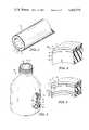
- FIG. 1is a perspective view of the tubular body of this invention
- FIGS. 2 and 3illustrate fragmentary cross sections of composite thermoplastic bodies of the subject invention
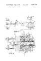
- FIG. 4is a cross-sectional view of a multimanifold die assembly for making the article of this invention
- FIG. 5is a view of a narrow neck container made from the tubular body of this invention.
- FIG. 6depicts a schematic representation of the apparatus for forming containers like FIG. 5 from tubular bodies of this invention.
- FIGS. 1, 2 and 3a sectional view of several rigid coextruded thermosplastic bodies are shown, each body itself being designated generally by reference numeral 10.
- the body 10comprises a first or outer polymeric material 11 bonded by a first glue layer 12 to a so-called unbalanced or uncentered inner layer 13 which in turn is bonded to a second or inner polymeric material 15 by a second glue layer 14.
- the inner polymeric materialmay comprise different polymeric materials such as shown by layers 15, 16 and 17 with inner glue layers 18 and 19.
- it has been found that such rigid structuresrender very favorable biaxially oriented containers or drawn-molded containers, which have a high barrier property to gases such as oxygen and are excellent in transparency, rigidity, mechanical strength and other physical properties.
- the multilayered structure of the subject inventioncomprises a tubular thermoplastic body having a barrier layer sandwiched between other thermoplastic materials, with a glue or adhesive resin layer interposed between said thermoplastic layers, the barrier layer being proximate the exterior surface of said structure.
- the barrier layerWhen the barrier layer is so situated, it has been observed that there is less tendency for its decomposition or degradation and the formation of organic or inorganic inclusions which become oftentimes entrapped in the polymeric matrix during formation of a coextruded tubular structure.
- the inclusionsmay often be hydrogen halides.
- the low gas permeable or barrier layershould be positioned away from the central plane of the sheet or tubular structure and is most preferably located towards the exterior portion, especially within the first one-third of layers of a given multilayered preform structure.
- the barrier layeris best located proximate the outer surface of the structure, being within about 1 percent to 33 percent of the total thickness and the barrier layer itself occupying from about 1 percent to 20 percent of said total thickness.
- the barrier layermay have a thickness substantially equal to the thickness of the first outer thermoplastic layer.
- the barrier layershould be situated within the outer 15 ⁇ 1 percent of the total thickness of the tubular body.
- FIGS. 2 and 3show one position of the barrier layer 13 and its relative thicknesses to the other layers within a given multilayered tubular body.
- thermoplastic materialsmay be used for the polymeric layers, that is, for those polymeric layers other than the at least one barrier layer of low gas permeability.
- the thermoplastic materialsinclude the solid olefins such as polyethylene, polypropylene and polybutylene.
- the polyolefins herein contemplatedinclude polyethylene, polypropylene, resinous copolymers of ethylene and propylene and polymers of ethylene and/or propylene with minor proportions of olefinically unsaturated monomers such as the low molecular weight olefins having, for example, from 2 to 8 carbon atoms such as 1-butene, 1-pentene, 1-hexene, 1-heptene, and 1-octene.
- Other hydrocarbons useful for the copolymers hereinare the copolymers of ethylene and propylene include divinylbenzene, allene, dimethallyl and isopentene.
- thermoplastic materials for the layers that are not the barrier layerare polystyrene, polymethacrylates including polymethyl methacrylate and polybutyl methacrylate; polyvinyl alcohols; polyvinyl halides; polyvinyl acetals including polyvinyl trityral, polyallyl alcohol and polyallyl acetate; polyesters including polyethylene terephthalate and polycarbornates.
- low gas permeability layer or barrier layeras used herein include polyvinylidene chloride and its copolymers; polyacrylonitrile and its copolymers including poly(acrylonitrile-co-styrene-co-butadiene); polyamides such as nylon; and hydrolized polymers of vinyl acetate and ethylene, especially saponified copolymers thereof.
- polyvinylidene chloride copolymersas used herein mean a polymeric material which contains at least 50 percent of vinylidene chloride.
- a preferred barrier layer in accordance with this inventionis polyvinylidene chloride and its copolymers.
- Copolymerizable monomers with vinylidene chlorideinclude vinyl chloride, butadiene, acrylonitrile, vinyl acetate, methyl acrylate, ethyl acrylate, butyl acrylate, and methyl methacrylate.
- Terpolymerscan also be employed, e.g., a terpolymer of vinylidene chloride, methyl methacrylate and vinyl chloride.
- thermoplastic layersas well as between the thermoplastic layers and the barrier layer.
- adhesive or bonding layersbetween the barrier layer and the other thermoplastic layers. This has many advantages including the preventing of entrapping air in the coextruded material.
- compositions which are particularly advantageousare copolymers containing about 13 weight percent to about 35 weight percent vinyl acetate with from about 87 weight percent to about 65 weight percent ethylene, copolymer compositions of from about 20 to 30 weight percent ethyl acrylate with from about 80 to 70 weight percent ethylene, copolymer compositions from about 20 to 30 weight percent isobutyl acrylate with from about 80 to ⁇ weight percent of ethylene and chlorinated polyethylene containing from about 25 to 40 weight percent chlorine and copolymers of butadiene-styrene.
- Suitable polymers or polymeric compositionsmay be readily selected by determining the bonding strength of the particular layer combination, usually by using peel strength tests.
- FIG. 4there is illustrated a sectional view of a multimanifold die device useful in forming the subject article, said device being generally designated by the reference numeral 20, the device 20 comprising a die body 21 having defined therein a centrally disposed aperture 22. Located within aperture 22 is a mandrel 40 equally spaced from the walls of the aperture 22 and secured to the device 20 by retaining member 41. Formed within the body 21 is first and second conduits 23 and 24 which carry melted thermoplastic and barrier materials P and B, respectively, into first and second plenums 25 and 26. Thermoplastic material P is divided into two streams that open into aperture 22, an inner stream 30 and an outer stream 31, said streams issuing from annular slots 28 and 27 that communicate with the plenum 25.
- a conduit 29communicates with a third plenum 24 for directing a suitable adhesive or glue material G.
- the glue material Gforms two streams, an inner stream 37 and an outer stream 38, said streams coming from glue slots 33 and 34.
- the barrier material Bis carried within the die body 21 by plenum 26 which, in turn, communicates with the aperture 22 by means of barrier slot 39. It will be appreciated that a number of die configurations may be used to form the article herein, the aforementioned being just one embodiment.
- FIG. 6there is shown a tubular structure 10 being formed by passing molten thermoplastic materials from three separate coventional screw-type extruders 51, 52 and 53 which contain thermoplastic material, glue, and barrier material, respectively, to the multimanifold die device 20 where melted thermoplastic materials are united into the tubular body 10 as previously described and, thereafter, the molten materials are allowed to pass into a vacuum cooling and sizing chamber 54.
- thermally sensitive barrier or low gas permeable layeris situated in the multilayered structure proximate the outer surface as defined herein whereby it may be quenched or cooled quickly.
- this particular location of the barrier layer, that is proximate the outer surfacealso reduces the forces due to the differential shrinkage of the inner and outer layers and, therefore, further curtails the tendency of the gaseous inclusions to form. As a result, the formation of gaseous inclusions is substantially reduced in making such multilayered tubular bodies in accordance with this invention.
- the solidified tubular bodyAfter being cooled the solidified tubular body is pushed via belts 56 and 57 into cutting means 58 where it is severed into individual open end parison preforms designated A. Thereafter, the preform A is passed through an air oven 59 where it is heated to a predetermined orientation temperature and the preform is then transferred by means not shown to a thread-forming head 61 whereby the thread and finish configuration is readily formed.
- the parison Ais grasped at the other end thereof by gripping fingers 62, which are brought together by means of cylinders or cams not shown, and relative movement effected between thread-forming head 61 and gripping fingers 62 by means of raising head 61 through the action of cylinder 63 to stretch the parison to the elongated condition depicted by reference character 60.
- preblow airis introduced through line 64 and mold halves 65 and 66 concurrently close on the thus-stretched parison 60.
- Sealing and severing inserts 55 in mold halves 65 and 66allow the mechanical operation of bringing the parison walls into intimate contact and severing the parison. It will be appreciated that since the innermost portion of the multilayered structure is substantially one polymeric material, e.g., polypropylene, that this action brings together a larger area of common polymeric material which readily seals itself to form the bottom end wall.
- three separate extruderswere used in a coextrusion line, the first (1) extruder hopper containing polypropylene copolymer having a density of about 0.90 and a crystalline melting point of about 330° F., the second (2) containing a copolymer of vinylidene chloride and vinyl chloride having a density of about 1.71 and a crystalline melting point of about 300° F.; and the third (3) extruder containing a resinous, adhesive material comprising about 40 percent styrene and 60 percent butadiene.
- Each extruded tubular body thus formedhad an outside diameter of about 1.25 inch and a wall thickness of about 0.230 inch.
- Each tubular bodywas cooled in a vacuum sizing and quenching chamber using a coolant at about 40° F., and thereafter cut into ten inch lengths.
- a copolymer of vinylidene chloride (about 85 percent) and vinyl chloride (about 15 percent)were made.
- the barrier layerwas bonded via the abovementioned adhesive material to both an inner and an outer layer of polypropylene.
- the barrier material itself as well as the other materialswere maintained substantially at the same quantitative level in each placement.
- the following tableshows the distance the barrier was located from the outer surface and indicates the average number of inclusions per foot as well as the estimated average inclusion volume. By multiplying the average number of inclusions per foot and estimated average inclusion volume and dividing by the inclusion volume per foot of Sample A the relative inclusion volume per foot is determined.
Landscapes
- Engineering & Computer Science (AREA)
- Mechanical Engineering (AREA)
- Manufacturing & Machinery (AREA)
- Laminated Bodies (AREA)
- Extrusion Moulding Of Plastics Or The Like (AREA)
Abstract
Description
TABLE ______________________________________ Samples DESCRIPTION A B C D E ______________________________________ 1.Average Outer 22 62 99 168 183 Polypropylene + Glue Layer Thickness, mils 2. Average Number 1.6 10.4 26.4 11.6 38.4 of Inclusions per Foot 3. Estimated Average 439 12800 31300 6800 531 Inclusion Volume 4. Relative Inclusion 1.0 190 1200 110 29 Volume per Foot ______________________________________
Claims (13)
Priority Applications (1)
| Application Number | Priority Date | Filing Date | Title |
|---|---|---|---|
| US06/485,760US4436778A (en) | 1981-10-05 | 1983-04-22 | Multilayer tubular body with uncentered barrier layer |
Applications Claiming Priority (2)
| Application Number | Priority Date | Filing Date | Title |
|---|---|---|---|
| US30829281A | 1981-10-05 | 1981-10-05 | |
| US06/485,760US4436778A (en) | 1981-10-05 | 1983-04-22 | Multilayer tubular body with uncentered barrier layer |
Related Parent Applications (1)
| Application Number | Title | Priority Date | Filing Date |
|---|---|---|---|
| US30829281AContinuation | 1981-10-05 | 1981-10-05 |
Publications (1)
| Publication Number | Publication Date |
|---|---|
| US4436778Atrue US4436778A (en) | 1984-03-13 |
Family
ID=26976175
Family Applications (1)
| Application Number | Title | Priority Date | Filing Date |
|---|---|---|---|
| US06/485,760Expired - LifetimeUS4436778A (en) | 1981-10-05 | 1983-04-22 | Multilayer tubular body with uncentered barrier layer |
Country Status (1)
| Country | Link |
|---|---|
| US (1) | US4436778A (en) |
Cited By (29)
| Publication number | Priority date | Publication date | Assignee | Title |
|---|---|---|---|---|
| US4609516A (en)* | 1984-02-17 | 1986-09-02 | Continental Pet Technologies, Inc. | Method of forming laminated preforms |
| US4649004A (en)* | 1983-12-27 | 1987-03-10 | Toyo Seikan Kaisha, Ltd. | Process for production of multi-layer pipes for draw-forming |
| US4728549A (en)* | 1984-10-31 | 1988-03-01 | Mitsubishi Gas Chemical Company, Inc. | Multilayered container |
| US4746562A (en)* | 1986-02-28 | 1988-05-24 | W. R. Grace & Co., Cryovac Div. | Packaging film |
| US4753700A (en)* | 1986-02-28 | 1988-06-28 | W. R. Grace & Co., Cryovac Div. | Packaging film |
| US4780258A (en)* | 1987-07-17 | 1988-10-25 | P.C.E. Corp. | Coextruded laminate having barrier layers |
| US4798526A (en)* | 1986-07-17 | 1989-01-17 | General Electric Company | Modular extrusion head |
| US4810542A (en)* | 1987-02-09 | 1989-03-07 | Kuraray Co., Ltd. | Multilayered tube for draw molding and multilayered container utilizing the tube |
| US4895744A (en)* | 1986-06-26 | 1990-01-23 | General Electric Company | Method of making a multi-layer parison |
| US4919985A (en)* | 1987-01-22 | 1990-04-24 | Toyo Seikan Kaisha, Ltd. | Coated styrene resin container and process for production thereof |
| US4943458A (en)* | 1987-12-31 | 1990-07-24 | Henkel Kommanditgesellschaft Auf Aktien | Hollow plastic body having a glossy surface |
| US4948643A (en)* | 1989-01-23 | 1990-08-14 | W. R. Grace & Co.-Conn. | Flexible medical solution tubing |
| US4990382A (en)* | 1987-09-11 | 1991-02-05 | Continental Plastic Containers, Inc. | Plastic container with glass-like appearance, parison for and method of making same |
| US5019433A (en)* | 1986-06-26 | 1991-05-28 | General Electric Corporation | Multi-layer molten plastic body |
| US5038833A (en)* | 1985-03-22 | 1991-08-13 | Technoform Caprano+Brunnhofer Kg | Fuel line for fixed-length vehicle installation |
| US5167259A (en)* | 1989-11-20 | 1992-12-01 | Technoform Caprano & Brunnhofer Kg | Three-layer fuel-line hose |
| US5215698A (en)* | 1991-11-25 | 1993-06-01 | Americraft Machined Products, Inc. | Extrusion tool and method of extrusion coating |
| US5236642A (en)* | 1987-12-31 | 1993-08-17 | American National Can Company | Multiple layer sheet materials, and packages, and methods and apparatus for making |
| US5349989A (en)* | 1990-06-29 | 1994-09-27 | Dunlop Coflexip Umbilicals Limited | Fluid transportation multiconduit umbilical |
| US5476120A (en)* | 1992-01-29 | 1995-12-19 | Technoform Caprano + Brunnhofer Kg | Lacquer-resistant fuel-line hose |
| US6041826A (en)* | 1993-06-03 | 2000-03-28 | Elf Atochem S.A. | Petrol supply tube |
| US6196826B1 (en) | 1999-05-28 | 2001-03-06 | Mold-Masters Limited | Seepage system for an injection molding apparatus |
| US6398537B2 (en) | 1999-04-02 | 2002-06-04 | Mold-Masters Limited | Shuttle system for an apparatus for injection molding |
| US6406767B1 (en) | 1992-03-30 | 2002-06-18 | Cryovac, Inc. | Medical solution tubing |
| US6440350B1 (en) | 1999-03-18 | 2002-08-27 | Mold-Masters Limited | Apparatus and method for multi-layer injection molding |
| US6648622B1 (en) | 1999-03-18 | 2003-11-18 | Mold Masters Limited | Apparatus and method for multi-layer injection molding |
| US20060112998A1 (en)* | 2004-12-01 | 2006-06-01 | Tekni-Plex, Inc. | Multi-layered hose |
| US20070252304A1 (en)* | 2006-04-26 | 2007-11-01 | Graham Packaging Company L.P. | Method for making multi-layer preform |
| US20220341514A1 (en)* | 2019-10-30 | 2022-10-27 | Flowlining Limited | Improved pipe liner and associated methods |
Citations (20)
| Publication number | Priority date | Publication date | Assignee | Title |
|---|---|---|---|---|
| US3308508A (en) | 1964-10-02 | 1967-03-14 | Dow Chemical Co | Die |
| US3354506A (en) | 1962-04-30 | 1967-11-28 | Union Carbide Corp | Apparatus for melt extrusion of multi-wall plastic tubing |
| US3570748A (en) | 1966-06-29 | 1971-03-16 | Standard Packaging Corp | Composite film and method |
| US3645838A (en) | 1970-02-02 | 1972-02-29 | Dow Chemical Co | Rigid multilayer formed sheet structures |
| US3686379A (en) | 1969-08-18 | 1972-08-22 | Phillips Petroleum Co | Sealing parisons using preblow and contoured sealing surface |
| US3821182A (en) | 1961-12-05 | 1974-06-28 | Grace W R & Co | Method for preparing of film of a vinylidene chloride polymer |
| US3908070A (en) | 1972-04-24 | 1975-09-23 | Dow Chemical Co | Multilayer thermoplastic barrier structure |
| US3912843A (en) | 1970-06-29 | 1975-10-14 | Milprint Inc | Flexible packaging film |
| US3924051A (en) | 1970-09-08 | 1975-12-02 | American Can Co | Oriented saran coextrudate |
| US4048428A (en) | 1961-12-05 | 1977-09-13 | W. R. Grace & Co. | Method for preparing a film of vinylidene chloride polymer |
| US4057667A (en) | 1972-03-24 | 1977-11-08 | American Can Company | Oriented saran coextrudate |
| US4112181A (en) | 1961-12-05 | 1978-09-05 | W. R. Grace & Co. | Method for preparing a film of vinylidene chloride polymer |
| US4123576A (en) | 1975-07-23 | 1978-10-31 | Kureha Kagaku Kogyo Kabushiki Kaisha | Bonding a multi-layered structure of olefin-containing and nitrile-containing polymers and article |
| US4139665A (en) | 1975-02-21 | 1979-02-13 | Lever Brothers Company | Packaging material |
| US4161562A (en) | 1976-12-29 | 1979-07-17 | Kureha Kagaku Kogyo Kabushiki Kaisha | Biaxially stretched five-layer film for packaging food |
| US4182457A (en) | 1976-08-10 | 1980-01-08 | Toyo Seikan Kaisha Limited | Multilayer container |
| US4247583A (en) | 1978-10-30 | 1981-01-27 | Roy Paul D | Insulating structure with polygonal cells |
| US4281045A (en) | 1979-11-29 | 1981-07-28 | Kyoraku Co., Ltd. | Multi-layer extruded article |
| US4288488A (en) | 1977-09-13 | 1981-09-08 | Kureha Kagaku Kogyo Kabushiki Kaisha | Laminated packing material with a high gas-impermeablility and an advantageous workability |
| US4341837A (en) | 1978-08-11 | 1982-07-27 | Kureha Kagaku Kogyo Kabushiki Kaisha | Laminar thermoplastic resin structure |
- 1983
- 1983-04-22USUS06/485,760patent/US4436778A/ennot_activeExpired - Lifetime
Patent Citations (20)
| Publication number | Priority date | Publication date | Assignee | Title |
|---|---|---|---|---|
| US3821182A (en) | 1961-12-05 | 1974-06-28 | Grace W R & Co | Method for preparing of film of a vinylidene chloride polymer |
| US4112181A (en) | 1961-12-05 | 1978-09-05 | W. R. Grace & Co. | Method for preparing a film of vinylidene chloride polymer |
| US4048428A (en) | 1961-12-05 | 1977-09-13 | W. R. Grace & Co. | Method for preparing a film of vinylidene chloride polymer |
| US3354506A (en) | 1962-04-30 | 1967-11-28 | Union Carbide Corp | Apparatus for melt extrusion of multi-wall plastic tubing |
| US3308508A (en) | 1964-10-02 | 1967-03-14 | Dow Chemical Co | Die |
| US3570748A (en) | 1966-06-29 | 1971-03-16 | Standard Packaging Corp | Composite film and method |
| US3686379A (en) | 1969-08-18 | 1972-08-22 | Phillips Petroleum Co | Sealing parisons using preblow and contoured sealing surface |
| US3645838A (en) | 1970-02-02 | 1972-02-29 | Dow Chemical Co | Rigid multilayer formed sheet structures |
| US3912843A (en) | 1970-06-29 | 1975-10-14 | Milprint Inc | Flexible packaging film |
| US3924051A (en) | 1970-09-08 | 1975-12-02 | American Can Co | Oriented saran coextrudate |
| US4057667A (en) | 1972-03-24 | 1977-11-08 | American Can Company | Oriented saran coextrudate |
| US3908070A (en) | 1972-04-24 | 1975-09-23 | Dow Chemical Co | Multilayer thermoplastic barrier structure |
| US4139665A (en) | 1975-02-21 | 1979-02-13 | Lever Brothers Company | Packaging material |
| US4123576A (en) | 1975-07-23 | 1978-10-31 | Kureha Kagaku Kogyo Kabushiki Kaisha | Bonding a multi-layered structure of olefin-containing and nitrile-containing polymers and article |
| US4182457A (en) | 1976-08-10 | 1980-01-08 | Toyo Seikan Kaisha Limited | Multilayer container |
| US4161562A (en) | 1976-12-29 | 1979-07-17 | Kureha Kagaku Kogyo Kabushiki Kaisha | Biaxially stretched five-layer film for packaging food |
| US4288488A (en) | 1977-09-13 | 1981-09-08 | Kureha Kagaku Kogyo Kabushiki Kaisha | Laminated packing material with a high gas-impermeablility and an advantageous workability |
| US4341837A (en) | 1978-08-11 | 1982-07-27 | Kureha Kagaku Kogyo Kabushiki Kaisha | Laminar thermoplastic resin structure |
| US4247583A (en) | 1978-10-30 | 1981-01-27 | Roy Paul D | Insulating structure with polygonal cells |
| US4281045A (en) | 1979-11-29 | 1981-07-28 | Kyoraku Co., Ltd. | Multi-layer extruded article |
Cited By (32)
| Publication number | Priority date | Publication date | Assignee | Title |
|---|---|---|---|---|
| US4649004A (en)* | 1983-12-27 | 1987-03-10 | Toyo Seikan Kaisha, Ltd. | Process for production of multi-layer pipes for draw-forming |
| US4741936A (en)* | 1983-12-27 | 1988-05-03 | Toyo Seikan Kaisha, Ltd. | Laminate preform for a multi-layer polyester bottle |
| US4609516A (en)* | 1984-02-17 | 1986-09-02 | Continental Pet Technologies, Inc. | Method of forming laminated preforms |
| US4728549A (en)* | 1984-10-31 | 1988-03-01 | Mitsubishi Gas Chemical Company, Inc. | Multilayered container |
| US5038833A (en)* | 1985-03-22 | 1991-08-13 | Technoform Caprano+Brunnhofer Kg | Fuel line for fixed-length vehicle installation |
| US4746562A (en)* | 1986-02-28 | 1988-05-24 | W. R. Grace & Co., Cryovac Div. | Packaging film |
| US4753700A (en)* | 1986-02-28 | 1988-06-28 | W. R. Grace & Co., Cryovac Div. | Packaging film |
| US5019433A (en)* | 1986-06-26 | 1991-05-28 | General Electric Corporation | Multi-layer molten plastic body |
| US4895744A (en)* | 1986-06-26 | 1990-01-23 | General Electric Company | Method of making a multi-layer parison |
| US4798526A (en)* | 1986-07-17 | 1989-01-17 | General Electric Company | Modular extrusion head |
| US4919985A (en)* | 1987-01-22 | 1990-04-24 | Toyo Seikan Kaisha, Ltd. | Coated styrene resin container and process for production thereof |
| US4810542A (en)* | 1987-02-09 | 1989-03-07 | Kuraray Co., Ltd. | Multilayered tube for draw molding and multilayered container utilizing the tube |
| US4780258A (en)* | 1987-07-17 | 1988-10-25 | P.C.E. Corp. | Coextruded laminate having barrier layers |
| US4990382A (en)* | 1987-09-11 | 1991-02-05 | Continental Plastic Containers, Inc. | Plastic container with glass-like appearance, parison for and method of making same |
| US4943458A (en)* | 1987-12-31 | 1990-07-24 | Henkel Kommanditgesellschaft Auf Aktien | Hollow plastic body having a glossy surface |
| US5236642A (en)* | 1987-12-31 | 1993-08-17 | American National Can Company | Multiple layer sheet materials, and packages, and methods and apparatus for making |
| US4948643A (en)* | 1989-01-23 | 1990-08-14 | W. R. Grace & Co.-Conn. | Flexible medical solution tubing |
| US5167259A (en)* | 1989-11-20 | 1992-12-01 | Technoform Caprano & Brunnhofer Kg | Three-layer fuel-line hose |
| US5349989A (en)* | 1990-06-29 | 1994-09-27 | Dunlop Coflexip Umbilicals Limited | Fluid transportation multiconduit umbilical |
| US5215698A (en)* | 1991-11-25 | 1993-06-01 | Americraft Machined Products, Inc. | Extrusion tool and method of extrusion coating |
| US5476120A (en)* | 1992-01-29 | 1995-12-19 | Technoform Caprano + Brunnhofer Kg | Lacquer-resistant fuel-line hose |
| US6406767B1 (en) | 1992-03-30 | 2002-06-18 | Cryovac, Inc. | Medical solution tubing |
| US6041826A (en)* | 1993-06-03 | 2000-03-28 | Elf Atochem S.A. | Petrol supply tube |
| US6440350B1 (en) | 1999-03-18 | 2002-08-27 | Mold-Masters Limited | Apparatus and method for multi-layer injection molding |
| US6648622B1 (en) | 1999-03-18 | 2003-11-18 | Mold Masters Limited | Apparatus and method for multi-layer injection molding |
| US6655945B1 (en) | 1999-03-18 | 2003-12-02 | Mold Masters Limited | Apparatus and method for multi-layer injection molding |
| US6398537B2 (en) | 1999-04-02 | 2002-06-04 | Mold-Masters Limited | Shuttle system for an apparatus for injection molding |
| US6196826B1 (en) | 1999-05-28 | 2001-03-06 | Mold-Masters Limited | Seepage system for an injection molding apparatus |
| US20060112998A1 (en)* | 2004-12-01 | 2006-06-01 | Tekni-Plex, Inc. | Multi-layered hose |
| US20070252304A1 (en)* | 2006-04-26 | 2007-11-01 | Graham Packaging Company L.P. | Method for making multi-layer preform |
| US20220341514A1 (en)* | 2019-10-30 | 2022-10-27 | Flowlining Limited | Improved pipe liner and associated methods |
| US11796091B2 (en)* | 2019-10-30 | 2023-10-24 | Flowlining Limited | Pipe liner and associated methods |
Similar Documents
| Publication | Publication Date | Title |
|---|---|---|
| US4436778A (en) | Multilayer tubular body with uncentered barrier layer | |
| EP0076366A2 (en) | Multilayer tubular body with uncentered barrier layer | |
| CA1240113A (en) | Process for production of multi-layer pipes for draw-forming | |
| US4522775A (en) | Apparatus and method for producing multilayered laminates | |
| US4824618A (en) | Coextrusion blowmolding process | |
| US6218024B1 (en) | Multilayer plastic film | |
| US3940001A (en) | Recyclable plastic containers | |
| US4064296A (en) | Heat shrinkable multi-layer film of hydrolyzed ethylene vinyl acetate and a cross-linked olefin polymer | |
| US4244914A (en) | Process for preparing gas-, vapor- and odor-proof coupled and coextruded multilayer articles of thermoplastic material and closed-surface bodies comprising the same | |
| RU2500540C2 (en) | Sandwich structures with circular profiles, method and device for their production | |
| US4990382A (en) | Plastic container with glass-like appearance, parison for and method of making same | |
| US5085821A (en) | Preparation of multi-layer drawn polyester bottles | |
| US5788926A (en) | Plastic bottle and process for making the same | |
| JPH0118849B2 (en) | ||
| GB2141970A (en) | Multi-layer drawn polyester bottle | |
| JPS6159896B2 (en) | ||
| CN1693153B (en) | Multi-layer polymer composite packaging container with nano-layer texture and processing method thereof | |
| GB2156265A (en) | Manufacturing thermoplastic tubular containers | |
| EP4342654B1 (en) | Crystal clear high barrier thermoformed plastic bottle | |
| JPS6320691B2 (en) | ||
| JPH0371008B2 (en) | ||
| JPH0367483B2 (en) | ||
| CA1270451A (en) | Apparatus and method for producing multi-layered laminates and improved multi-layered laminates produced therefrom | |
| JPS60147306A (en) | Manufacture of multilayer pipe for forming orientation molding | |
| JP2697101B2 (en) | Multilayer container |
Legal Events
| Date | Code | Title | Description |
|---|---|---|---|
| STCF | Information on status: patent grant | Free format text:PATENTED CASE | |
| MAFP | Maintenance fee payment | Free format text:PAYMENT OF MAINTENANCE FEE, 4TH YEAR, PL 97-247 (ORIGINAL EVENT CODE: M173); ENTITY STATUS OF PATENT OWNER: LARGE ENTITY Year of fee payment:4 | |
| FEPP | Fee payment procedure | Free format text:PAYOR NUMBER ASSIGNED (ORIGINAL EVENT CODE: ASPN); ENTITY STATUS OF PATENT OWNER: LARGE ENTITY | |
| MAFP | Maintenance fee payment | Free format text:PAYMENT OF MAINTENANCE FEE, 8TH YEAR, PL 97-247 (ORIGINAL EVENT CODE: M174); ENTITY STATUS OF PATENT OWNER: LARGE ENTITY Year of fee payment:8 | |
| AS | Assignment | Owner name:ALLTRISTA CORPORATION, INDIANA Free format text:ASSIGNMENT OF ASSIGNORS INTEREST;ASSIGNOR:BALL CORPORATION;REEL/FRAME:006622/0001 Effective date:19930402 | |
| MAFP | Maintenance fee payment | Free format text:PAYMENT OF MAINTENANCE FEE, 12TH YEAR, LARGE ENTITY (ORIGINAL EVENT CODE: M185); ENTITY STATUS OF PATENT OWNER: LARGE ENTITY Year of fee payment:12 | |
| FEPP | Fee payment procedure | Free format text:PAYER NUMBER DE-ASSIGNED (ORIGINAL EVENT CODE: RMPN); ENTITY STATUS OF PATENT OWNER: LARGE ENTITY | |
| AS | Assignment | Owner name:BANK OF AMERICA, N.A., AS ADMINISTRATIVE AGENT, NO Free format text:SECURITY AGREEMENT;ASSIGNOR:ALLTRISTA CORPORATION;REEL/FRAME:013240/0682 Effective date:20020424 | |
| AS | Assignment | Owner name:JARDEN CORPORATION, NEW YORK Free format text:CHANGE OF NAME;ASSIGNOR:ALLTRISTA CORPORATION;REEL/FRAME:013110/0430 Effective date:20020530 |