US4436164A - Lubrication failure detection system - Google Patents
Lubrication failure detection systemDownload PDFInfo
- Publication number
- US4436164A US4436164AUS06/356,853US35685382AUS4436164AUS 4436164 AUS4436164 AUS 4436164AUS 35685382 AUS35685382 AUS 35685382AUS 4436164 AUS4436164 AUS 4436164A
- Authority
- US
- United States
- Prior art keywords
- orifice
- failure detection
- detection system
- drilling fluid
- lubrication failure
- Prior art date
- Legal status (The legal status is an assumption and is not a legal conclusion. Google has not performed a legal analysis and makes no representation as to the accuracy of the status listed.)
- Expired - Fee Related
Links
Images

Classifications
- E—FIXED CONSTRUCTIONS
- E21—EARTH OR ROCK DRILLING; MINING
- E21B—EARTH OR ROCK DRILLING; OBTAINING OIL, GAS, WATER, SOLUBLE OR MELTABLE MATERIALS OR A SLURRY OF MINERALS FROM WELLS
- E21B12/00—Accessories for drilling tools
- E21B12/02—Wear indicators
- E—FIXED CONSTRUCTIONS
- E21—EARTH OR ROCK DRILLING; MINING
- E21B—EARTH OR ROCK DRILLING; OBTAINING OIL, GAS, WATER, SOLUBLE OR MELTABLE MATERIALS OR A SLURRY OF MINERALS FROM WELLS
- E21B10/00—Drill bits
- E21B10/08—Roller bits
- E21B10/22—Roller bits characterised by bearing, lubrication or sealing details
- E21B10/24—Roller bits characterised by bearing, lubrication or sealing details characterised by lubricating details
- E—FIXED CONSTRUCTIONS
- E21—EARTH OR ROCK DRILLING; MINING
- E21B—EARTH OR ROCK DRILLING; OBTAINING OIL, GAS, WATER, SOLUBLE OR MELTABLE MATERIALS OR A SLURRY OF MINERALS FROM WELLS
- E21B47/00—Survey of boreholes or wells
- E21B47/09—Locating or determining the position of objects in boreholes or wells, e.g. the position of an extending arm; Identifying the free or blocked portions of pipes
- E21B47/095—Locating or determining the position of objects in boreholes or wells, e.g. the position of an extending arm; Identifying the free or blocked portions of pipes by detecting an acoustic anomalies, e.g. using mud-pressure pulses
Definitions
- This inventionrelates in general to systems for providing lubrication to rotary drill bits in earth boring systems and in particular to lubrication systems which include means for remotely detecting the imminent failure of the lubrication system.
- the lubrication of earth boring drilling systemshas long represented a problem in the area.
- the pressures and temperatures encountered by a rotary drill bit during an earth boring operationmay fluctuate over a wide range.
- the hydrostatic pressure near the bitmay be as high as five thousand psi due to the weight of the drilling fluid in the well bore above the bit. Additionally, the friction of operation and the increase in depth will result in elevated temperatures at and near the drill bit.
- known systemshave been designed with pressure compensators to maintain lubricant pressure within the rotary drill bit.
- Such pressure compensatorstypically utilize a flexible membrane or diaphragm situated between a lubricant reservoir and the pressures exerted by the drilling fluid within the well bore. In this manner, the pressures of lubricant and drilling fluid may be equalized and proper lubricant flow to the bearing surfaces can be maintained as the lubricant is forced from the reservoir during higher pressure drilling operations.
- a rotary drill bitcannot be operated for an extended period of time without lubrication without the possibility of damage to or complete failure of the drill bit. In such cases, the drill bit, or portions of it, may break off and the drill string must be removed and the drill bit must be fished out of the well bore at great expense in both time and effort. As a result, it is a common practice to operate a rotary drill bit for some predetermined period of time and then remove the drill bit and recharge the lubricant reservoir or replace the drill bit. This operation is also time consuming and may be inefficient due to the inability of the drilling operators to accurately gauge the amount of lubrication remaining in a drill bit. Thermocouples and other remote reading instrumentation approaches have not proven practical in this area.
- a lubrication failure detection systemis implemented for utilization with an earth boring drilling system having at least one rotary drill bit coupled to a drill string, the drill string having an internal passage adapted to receive drilling fluid under pressure.
- At least one lubrication reservoiris disposed near said rotary drill bit and coupled to bearing surfaces within said rotary drill bit by a lubrication passageway.
- a flexible membraneseparates the lubrication reservoir from drilling fluid within the annulus formed by the rotary drill bit and distends inward in response to the pressure of the drilling fluid.
- the distention of the membraneforces lubricant into the lubrication passageway and when the membrane has distended to a selected point, the membrane actuates a mechanism which opens an orifice into the internal passage of the drill string, thereby abruptly decreasing the pressure of the drilling fluid within the drill string.
- the systemalso includes means for detecting this pressure drop, thereby indicating the imminent failure of lubrication within the system.
- the above described systemalso includes means for selectively closing the aforementioned orifice to permit additional operation of the drilling system after imminent lubrication failure has been indicated.
- FIG. 1is a sectional view of a portion of an earth boring drilling system incorporating the novel lubrication failure detection system of the present invention.
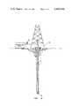
- FIG. 2is a partially schematic view of a portion of an earth boring drilling system incorporating the novel lubrication failure detection system of the present invention.
- Earth boring drilling system 10which incorporates the novel lubrication failure detection system of the present invention.
- Earth boring drilling system 10includes at least one cutter or rotating drillhead 12, which is mounted upon shaft 14.
- Shaft 14is mounted in any suitable manner to drill string 16.
- Drill string 16includes an internal passage 18, through which drilling fluid is conducted downwardly under pressure to orifice 20.
- the drilling fluid exuded from orifice 20is directed at cutter 12 and is then forced upward in the annulus surrounding drill string 16 by the pressure of the drilling fluid supply.
- the drilling fluidis utilized to carry cuttings and debris from drilling operations to the surface.
- Those skilled in the artwill appreciate that in a typical drilling operation a plurality of cutters and drilling fluid orifices will be utilized and that the drilling fluid must be supplied to the drill string at sufficient pressures to force drilling debris upward through the well bore.
- Cutter 12is typically mounted to shaft 14 by any combination of roller bearings such as roller bearings 22 and 24 and ball bearings such as ball bearings 26 and 28. Other types of bearing surfaces may also be used. Without a pressure compensating lubrication system the pressure of the drilling fluid would soon cause the drilling fluid and drilling debris to be forced into the bearing races and onto the bearing surfaces of cutter 12 thereby having an adverse effect upon continued operation of the system.
- the pressure compensated lubrication systemcomprises lubricant reservoir 30 which is separated from the drilling fluid within the annulus by flexible membrane 32.
- Flexible membrane 32is typically constructed of neoprene or other flexible material and may also be fabricated from a flexible metallic substance.
- Lubrication passageway 34is coupled, in one embodiment of the present invention, to a central lubrication channel 36 within shaft 14.
- the lubricant within channel 36is then applied, under pressure, to the bearings, bearing races and bearing surfaces upon which cutter 12 is mounted.
- the lubricant within the systemis kept at a pressure which corresponds to the ambient pressure of the drilling fluid surrounding cutter 12, and drilling fluid and debris are kept out of the bearing surfaces upon which cutter 12 will rotate.
- Piston 38is mounted within bore 40 and biased toward membrane 32 by spring 42. As membrane 32 reaches a point near the maximum distention into lubrication reservoir 30, membrane 32 will contact piston 38 and urge piston 38 into bore 40 against the bias provided by spring 42. As piston 38 is urged further into bore 40, the lowered shoulder portion of piston 38 will be positioned beneath rod 44. Rod 44 is then urged downward by the combined forces of spring 46 and the pressure of plug 48 upon cam surface 50.
- meansare provided for temporarily, blocking bore 52 to permit operation of earth boring drilling system 10 for an additional period of time after plug 48 has been released.
- a coarse grid or mesh 58is positioned in internal passage 18 as depicted in FIG. 1. After the drop in drilling fluid pressure has been detected, a ball check 60 may be dropped into internal passage 18. Ball check 60 will be directed into bore 52 by mesh 58 and will lodge against the beveled sides of bore 52. In this manner, bore 52 may be effectively closed, and the operation of earth boring drilling system 10 may continue for a short period of time after imminent lubrication failure has been indicated.
- FIG. 2depicts the drill string 16 within an annulus or well bore 17 in the earth.
- a drilling platform 62supports the machinery for operating earth boring drilling system 10.
- a drilling fluid supply source 64is coupled to internal passage 18 (not shown) of drill string 16 through pressure gauge 66.
- Pressure gauge 66is utilized to detect the drop in drilling fluid pressure created by the opening of bore 52 (also not shown). In alternate embodiments pressure gauge 66 may be monitored by an operator or coupled to an electronic circuit for pressure drop detection.
Landscapes
- Engineering & Computer Science (AREA)
- Mining & Mineral Resources (AREA)
- Geology (AREA)
- Life Sciences & Earth Sciences (AREA)
- Physics & Mathematics (AREA)
- Fluid Mechanics (AREA)
- Environmental & Geological Engineering (AREA)
- General Life Sciences & Earth Sciences (AREA)
- Geochemistry & Mineralogy (AREA)
- Mechanical Engineering (AREA)
- Geophysics (AREA)
- Acoustics & Sound (AREA)
- Earth Drilling (AREA)
Abstract
Description
Claims (19)
Priority Applications (1)
| Application Number | Priority Date | Filing Date | Title |
|---|---|---|---|
| US06/356,853US4436164A (en) | 1982-03-10 | 1982-03-10 | Lubrication failure detection system |
Applications Claiming Priority (1)
| Application Number | Priority Date | Filing Date | Title |
|---|---|---|---|
| US06/356,853US4436164A (en) | 1982-03-10 | 1982-03-10 | Lubrication failure detection system |
Publications (1)
| Publication Number | Publication Date |
|---|---|
| US4436164Atrue US4436164A (en) | 1984-03-13 |
Family
ID=23403241
Family Applications (1)
| Application Number | Title | Priority Date | Filing Date |
|---|---|---|---|
| US06/356,853Expired - Fee RelatedUS4436164A (en) | 1982-03-10 | 1982-03-10 | Lubrication failure detection system |
Country Status (1)
| Country | Link |
|---|---|
| US (1) | US4436164A (en) |
Cited By (19)
| Publication number | Priority date | Publication date | Assignee | Title |
|---|---|---|---|---|
| US4548280A (en)* | 1984-02-15 | 1985-10-22 | Reed Rock Bit Company | Drill bit having a failure indicator |
| US4610313A (en)* | 1984-02-15 | 1986-09-09 | Reed Tool Company | Drill bit having a failure indicator |
| US4688647A (en)* | 1984-02-15 | 1987-08-25 | Reed Tool Company | Drill bit having a failure indicator |
| US6230822B1 (en)* | 1995-02-16 | 2001-05-15 | Baker Hughes Incorporated | Method and apparatus for monitoring and recording of the operating condition of a downhole drill bit during drilling operations |
| US6484824B2 (en) | 2000-08-23 | 2002-11-26 | Schlumberger Technology Corporation | Failure indicator for rolling cutter drill bit |
| US20030042049A1 (en)* | 2001-04-26 | 2003-03-06 | Halliburton Energy Services, Inc. | Roller cone bits with reduced packing |
| US6571886B1 (en) | 1995-02-16 | 2003-06-03 | Baker Hughes Incorporated | Method and apparatus for monitoring and recording of the operating condition of a downhole drill bit during drilling operations |
| US6631772B2 (en) | 2000-08-21 | 2003-10-14 | Halliburton Energy Services, Inc. | Roller bit rearing wear detection system and method |
| US6634441B2 (en) | 2000-08-21 | 2003-10-21 | Halliburton Energy Services, Inc. | System and method for detecting roller bit bearing wear through cessation of roller element rotation |
| US6648082B2 (en) | 2000-11-07 | 2003-11-18 | Halliburton Energy Services, Inc. | Differential sensor measurement method and apparatus to detect a drill bit failure and signal surface operator |
| US6691802B2 (en) | 2000-11-07 | 2004-02-17 | Halliburton Energy Services, Inc. | Internal power source for downhole detection system |
| US6712160B1 (en) | 2000-11-07 | 2004-03-30 | Halliburton Energy Services Inc. | Leadless sub assembly for downhole detection system |
| US6722450B2 (en) | 2000-11-07 | 2004-04-20 | Halliburton Energy Svcs. Inc. | Adaptive filter prediction method and system for detecting drill bit failure and signaling surface operator |
| US6725947B2 (en)* | 2000-08-21 | 2004-04-27 | Halliburton Energy Services, Inc. | Roller bits with bearing failure indication, and related methods, systems, and methods of manufacturing |
| US6817425B2 (en) | 2000-11-07 | 2004-11-16 | Halliburton Energy Serv Inc | Mean strain ratio analysis method and system for detecting drill bit failure and signaling surface operator |
| US20080044040A1 (en)* | 2004-10-22 | 2008-02-21 | Werner Alan J Jr | Method and apparatus for intelligent acoustic signal processing in accordance with a user preference |
| US20100326735A1 (en)* | 2009-06-30 | 2010-12-30 | Hall David R | Downhole Lubrication System |
| WO2012060713A1 (en) | 2010-10-21 | 2012-05-10 | Tco As | Device to operate downhole equipment |
| EP2948612A4 (en)* | 2013-01-25 | 2017-02-22 | Halliburton Energy Services, Inc. | Hydraulic activation of mechanically operated bottom hole assembly tool |
Citations (6)
| Publication number | Priority date | Publication date | Assignee | Title |
|---|---|---|---|---|
| US2580860A (en) | 1949-03-04 | 1952-01-01 | Reed Roller Bit Co | Wear indicating device for drill bits |
| US2647729A (en) | 1949-09-22 | 1953-08-04 | Reed Roller Bit Co | Wear indicating device for drill bits |
| US3062302A (en) | 1960-05-09 | 1962-11-06 | Shell Oil Co | Indicator device for bearing failures in drill bits |
| US3096835A (en) | 1962-01-02 | 1963-07-09 | Smith Ind International Inc | Bearing seal for rotary rock bits |
| US3853184A (en) | 1970-09-04 | 1974-12-10 | D Mccullough | Means for detecting wear on well drill bits |
| US4284149A (en) | 1979-04-27 | 1981-08-18 | Engineering Enterprises, Inc. | Well drilling tool |
- 1982
- 1982-03-10USUS06/356,853patent/US4436164A/ennot_activeExpired - Fee Related
Patent Citations (6)
| Publication number | Priority date | Publication date | Assignee | Title |
|---|---|---|---|---|
| US2580860A (en) | 1949-03-04 | 1952-01-01 | Reed Roller Bit Co | Wear indicating device for drill bits |
| US2647729A (en) | 1949-09-22 | 1953-08-04 | Reed Roller Bit Co | Wear indicating device for drill bits |
| US3062302A (en) | 1960-05-09 | 1962-11-06 | Shell Oil Co | Indicator device for bearing failures in drill bits |
| US3096835A (en) | 1962-01-02 | 1963-07-09 | Smith Ind International Inc | Bearing seal for rotary rock bits |
| US3853184A (en) | 1970-09-04 | 1974-12-10 | D Mccullough | Means for detecting wear on well drill bits |
| US4284149A (en) | 1979-04-27 | 1981-08-18 | Engineering Enterprises, Inc. | Well drilling tool |
Cited By (28)
| Publication number | Priority date | Publication date | Assignee | Title |
|---|---|---|---|---|
| US4548280A (en)* | 1984-02-15 | 1985-10-22 | Reed Rock Bit Company | Drill bit having a failure indicator |
| US4610313A (en)* | 1984-02-15 | 1986-09-09 | Reed Tool Company | Drill bit having a failure indicator |
| US4688647A (en)* | 1984-02-15 | 1987-08-25 | Reed Tool Company | Drill bit having a failure indicator |
| US6230822B1 (en)* | 1995-02-16 | 2001-05-15 | Baker Hughes Incorporated | Method and apparatus for monitoring and recording of the operating condition of a downhole drill bit during drilling operations |
| US6419032B1 (en)* | 1995-02-16 | 2002-07-16 | Baker Hughes Incorporated | Method and apparatus for monitoring and recording of the operating condition of a downhole drill bit during drilling operations |
| US6571886B1 (en) | 1995-02-16 | 2003-06-03 | Baker Hughes Incorporated | Method and apparatus for monitoring and recording of the operating condition of a downhole drill bit during drilling operations |
| US6725947B2 (en)* | 2000-08-21 | 2004-04-27 | Halliburton Energy Services, Inc. | Roller bits with bearing failure indication, and related methods, systems, and methods of manufacturing |
| US6631772B2 (en) | 2000-08-21 | 2003-10-14 | Halliburton Energy Services, Inc. | Roller bit rearing wear detection system and method |
| US6634441B2 (en) | 2000-08-21 | 2003-10-21 | Halliburton Energy Services, Inc. | System and method for detecting roller bit bearing wear through cessation of roller element rotation |
| US6484824B2 (en) | 2000-08-23 | 2002-11-26 | Schlumberger Technology Corporation | Failure indicator for rolling cutter drill bit |
| GB2368360B (en)* | 2000-10-27 | 2003-08-06 | Baker Hughes Inc | Drill bit |
| US6722450B2 (en) | 2000-11-07 | 2004-04-20 | Halliburton Energy Svcs. Inc. | Adaptive filter prediction method and system for detecting drill bit failure and signaling surface operator |
| US6691802B2 (en) | 2000-11-07 | 2004-02-17 | Halliburton Energy Services, Inc. | Internal power source for downhole detection system |
| US6712160B1 (en) | 2000-11-07 | 2004-03-30 | Halliburton Energy Services Inc. | Leadless sub assembly for downhole detection system |
| US6648082B2 (en) | 2000-11-07 | 2003-11-18 | Halliburton Energy Services, Inc. | Differential sensor measurement method and apparatus to detect a drill bit failure and signal surface operator |
| US6817425B2 (en) | 2000-11-07 | 2004-11-16 | Halliburton Energy Serv Inc | Mean strain ratio analysis method and system for detecting drill bit failure and signaling surface operator |
| US7357197B2 (en) | 2000-11-07 | 2008-04-15 | Halliburton Energy Services, Inc. | Method and apparatus for monitoring the condition of a downhole drill bit, and communicating the condition to the surface |
| US20030042049A1 (en)* | 2001-04-26 | 2003-03-06 | Halliburton Energy Services, Inc. | Roller cone bits with reduced packing |
| US7044242B2 (en) | 2001-04-26 | 2006-05-16 | Halliburton Energy Services, Inc. | Roller cone bits with reduced packing |
| US20080044040A1 (en)* | 2004-10-22 | 2008-02-21 | Werner Alan J Jr | Method and apparatus for intelligent acoustic signal processing in accordance with a user preference |
| US20100326735A1 (en)* | 2009-06-30 | 2010-12-30 | Hall David R | Downhole Lubrication System |
| US20100326736A1 (en)* | 2009-06-30 | 2010-12-30 | Hall David R | Downhole Lubrication System |
| US8020637B2 (en)* | 2009-06-30 | 2011-09-20 | Schlumberger Technology Corporation | Downhole lubrication system |
| US8141662B2 (en)* | 2009-06-30 | 2012-03-27 | Schlumberger Technology Corporation | Downhole lubrication system |
| WO2012060713A1 (en) | 2010-10-21 | 2012-05-10 | Tco As | Device to operate downhole equipment |
| RU2558562C2 (en)* | 2010-10-21 | 2015-08-10 | ТиСиО АС | Borehole equipment control device |
| AU2011324132B2 (en)* | 2010-10-21 | 2015-12-17 | Tco As | Device to operate downhole equipment |
| EP2948612A4 (en)* | 2013-01-25 | 2017-02-22 | Halliburton Energy Services, Inc. | Hydraulic activation of mechanically operated bottom hole assembly tool |
Similar Documents
| Publication | Publication Date | Title |
|---|---|---|
| US4436164A (en) | Lubrication failure detection system | |
| US4655300A (en) | Method and apparatus for detecting wear of a rotatable bit | |
| US6626251B1 (en) | Method and apparatus for monitoring and recording of the operating condition of a downhole drill bit during drilling operations | |
| JPS6361471B2 (en) | ||
| RU2330158C2 (en) | Method and device for data collection on well characteristics in process of drilling | |
| US3853184A (en) | Means for detecting wear on well drill bits | |
| US7066280B2 (en) | Method and apparatus for monitoring and recording of the operating condition of a downhole drill bit during drilling operations | |
| US4610313A (en) | Drill bit having a failure indicator | |
| CA1104383A (en) | Lubricant volume displacement system for a rotary rock bit | |
| US12410699B2 (en) | Apparatus and method for measuring drilling parameters of a down-the-hole drilling operation for mineral exploration | |
| US3303898A (en) | Bearing sealing and lubricating device | |
| US3719241A (en) | Free breathing lubrication system for sealed bearing rock bits | |
| US5339915A (en) | Drilling apparatus, particularly wire line core drilling apparatus | |
| US2906504A (en) | Lubrication of bearings | |
| CA2100010A1 (en) | Refrigerant-cooled downhole tool and method | |
| US4548280A (en) | Drill bit having a failure indicator | |
| US3048230A (en) | Lubricator for rock bit | |
| US4073548A (en) | Sealing system for a rotary rock bit | |
| US3721306A (en) | Pressure equalizing system for rock bits | |
| GB2164682A (en) | Self-adjusting valve actuator | |
| US5183123A (en) | Indicating means for a rock bit lubricating system | |
| US4688647A (en) | Drill bit having a failure indicator | |
| US4699352A (en) | Apparatus for well logging telemetry | |
| US4274498A (en) | Rock bit lubrication system utilizing expellable plug for obtaining expansion space | |
| US3735825A (en) | Pressure equalizing system for rock bits |
Legal Events
| Date | Code | Title | Description |
|---|---|---|---|
| AS | Assignment | Owner name:GLOBE OIL TOOLS, INC. FORT WORTH, TX A CORP. OF TX Free format text:ASSIGNMENT OF ASSIGNORS INTEREST.;ASSIGNOR:GARNER, LLOYD L.;REEL/FRAME:003991/0684 Effective date:19820305 | |
| MAFP | Maintenance fee payment | Free format text:PAYMENT OF MAINTENANCE FEE, 4TH YEAR, PL 96-517 (ORIGINAL EVENT CODE: M170); ENTITY STATUS OF PATENT OWNER: SMALL ENTITY Year of fee payment:4 | |
| FEPP | Fee payment procedure | Free format text:PAYOR NUMBER ASSIGNED (ORIGINAL EVENT CODE: ASPN); ENTITY STATUS OF PATENT OWNER: SMALL ENTITY | |
| AS | Assignment | Owner name:ROCK BIT INDUSTRIES U.S.A., INC. Free format text:ASSIGNMENT OF ASSIGNORS INTEREST.;ASSIGNOR:GLOBE OIL TOOLS, INC., A CORP. OF TX;REEL/FRAME:004841/0229 Effective date:19880226 Owner name:ROCK BIT INDUSTRIES U.S.A., INC.,STATELESS Free format text:ASSIGNMENT OF ASSIGNORS INTEREST;ASSIGNOR:GLOBE OIL TOOLS, INC., A CORP. OF TX;REEL/FRAME:004841/0229 Effective date:19880226 | |
| FEPP | Fee payment procedure | Free format text:MAINTENANCE FEE REMINDER MAILED (ORIGINAL EVENT CODE: REM.); ENTITY STATUS OF PATENT OWNER: SMALL ENTITY | |
| LAPS | Lapse for failure to pay maintenance fees | ||
| FP | Lapsed due to failure to pay maintenance fee | Effective date:19920315 | |
| STCH | Information on status: patent discontinuation | Free format text:PATENT EXPIRED DUE TO NONPAYMENT OF MAINTENANCE FEES UNDER 37 CFR 1.362 |