US4435238A - Manufacturing process for a low loss optical fiber cable - Google Patents
Manufacturing process for a low loss optical fiber cableDownload PDFInfo
- Publication number
- US4435238A US4435238AUS06/437,392US43739282AUS4435238AUS 4435238 AUS4435238 AUS 4435238AUS 43739282 AUS43739282 AUS 43739282AUS 4435238 AUS4435238 AUS 4435238A
- Authority
- US
- United States
- Prior art keywords
- tape
- strength member
- optical fiber
- fiber
- laid
- Prior art date
- Legal status (The legal status is an assumption and is not a legal conclusion. Google has not performed a legal analysis and makes no representation as to the accuracy of the status listed.)
- Expired - Lifetime
Links
Images
Classifications
- G—PHYSICS
- G02—OPTICS
- G02B—OPTICAL ELEMENTS, SYSTEMS OR APPARATUS
- G02B6/00—Light guides; Structural details of arrangements comprising light guides and other optical elements, e.g. couplings
- G02B6/44—Mechanical structures for providing tensile strength and external protection for fibres, e.g. optical transmission cables
- G02B6/4479—Manufacturing methods of optical cables
- G02B6/449—Twisting
- G02B6/4491—Twisting in a lobe structure
- G—PHYSICS
- G02—OPTICS
- G02B—OPTICAL ELEMENTS, SYSTEMS OR APPARATUS
- G02B6/00—Light guides; Structural details of arrangements comprising light guides and other optical elements, e.g. couplings
- G02B6/44—Mechanical structures for providing tensile strength and external protection for fibres, e.g. optical transmission cables
- G02B6/4401—Optical cables
- G02B6/4407—Optical cables with internal fluted support member
- G—PHYSICS
- G02—OPTICS
- G02B—OPTICAL ELEMENTS, SYSTEMS OR APPARATUS
- G02B6/00—Light guides; Structural details of arrangements comprising light guides and other optical elements, e.g. couplings
- G02B6/44—Mechanical structures for providing tensile strength and external protection for fibres, e.g. optical transmission cables
- G02B6/4401—Optical cables
- G02B6/4429—Means specially adapted for strengthening or protecting the cables
- G02B6/4434—Central member to take up tensile loads
Definitions
- the present inventionrelates to a method of manufacturing an optical fiber cable. More particularly, the present invention relates to a method of manufacturing an optical fiber cable of the type having a central strength member and one or more optical fibers laid about the central strength member in a protected manner.
- Optical fibershave become a desirable information transmitting medium due to their broad bandwidth capacity and small physical size and weight relative to metal electrical conductors.
- a number of characteristics of optical fibersincluding their susceptibility to breakage and their bending and stress losses pose serious problems in their use. It is therefore, necessary to find suitable means to protect the fibers.
- optical fiber ribbonsOne approach to the above problems has been to start with a plurality of optical fibers and to form them into linear arrays packaged in ribbon-like structures. This approach is described in detail in U.S. Pat. No. 4,129,468, issued Dec. 12, 1978.
- the requirements imposed on such optical fiber ribbonsinclude the need to provide mechanical stripability for ease of cable termination and splicing; the need for small size; the need for resistance to breakage when subjected to tensile stress; the need for individual fiber identification within the ribbon; and, the need to protect the ribbon from distorting forces which may cause deterioration of the optical signal.
- the fibersmay be longer than the length of the corresponding surrounding sheath by either winding the fibers around a central core within the sheath or by imparting a helical bend to the fibers and laying them loosely within the sheath.
- the patentgoes on to assert that the provision of a tubular sheath into which the optical fiber is inserted provides a protective structure which shields the surface of the fiber from radial compressive force and from contact with corrosive substances.
- a stretch memberis paid off from a neutralizer payoff in such manner that the strength member is rotating.
- a tape having longitudinal groovesis paid off from a fixed payoff and passed through a forming die.
- the strength memberis passed through the forming die, and the tape is applied to the exterior of the strength member.
- the tapeobtains a helical lay about the strength member.
- An optical fiberis paid off from a neutralizer payoff and laid into a groove on said tape. In the cable unit so formed, the optical fiber lays in the groove in the tape.
- Such a grooveis preferably formed by folding the tape.
- the tapemay be folded into a corrugated shape. In this manner, a plurality of grooves may be provided in the tape and one or more optical fibers may be laid into each groove. Since the tape is helically laid about the central strength member, the optical fibers then have a helical lay as well, thereby reducing the risk of stress-related loss in the fibers. Additional reduction in fiber stress is obtained as a result of the twist provided to the fibers when paid off from their neutralizer payoffs. This twist compensates for stresses which would otherwise be encountered when the fibers are helically wound about the strength member. In order to provide additional protection for the optical fibers, an outer tape may be helically laid over the corrugated tape in order to cover the fibers.
- This tapemay also be corrugated. Filling compound may be utilized in the manufacture of this cable, and it may be applied under and over the grooves of the corrugated tape. A binder may be provided in order to secure the outer tape over the fiber. This is deemed unnecessary if the cable unit is not to be combined with other cable units to form a composite high fiber count cable.
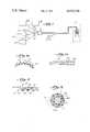
- FIG. 1illustrates an arrangement for manufacturing an optical fiber cable unit according to the invention.
- FIGS. 1a and 1bshow the overlap of the corrugated tape disclosed with regard to the invention.
- FIG. 2is a cross-section of a portion of the folded spacing tape covered with an outer tape.
- FIG. 3is a cross-sectional view of an optical fiber cable unit made in accordance with the invention.
- the axial strength member 11is paid off from a supply reel in such a way that it experiences no torsional stress. This can be accomplished by feeding the member 11 from conventional apparatus known as a neutralizer payoff 22. Rotation is imparted to strength member 11 as a result of the rotational motion imparted by the take-up reel of the type known as a single twist closer 21.
- a corrugated or folded splicing tape 12is paid off from fixed payoff 23, that is, a reel rotating about a fixed axis, and directed to a tape forming die 29.
- the strength member 11 and tape 12are passed through the forming die 29 wherein the tape is folded about the strength member.
- the tape 12assumes a helical lay about the strength member.
- Optical fibers 13are paid off from supply reels such as neutralizer payoffs 25a, 25b so that they, too, do not experience any torsional stress.
- Plate 28, a part of the tape forming die 29,includes a plurality of guide means, for instance, holes that direct the fibers 13 to a closing die 30.
- the fibers 13are laid into longitudinal grooves in the tape 12.
- Filling compoundmay optionally be provided about the optical fibers. This is accomplished by filling compound applicator 24 which includes, for instance, a supply tube located in front of the closing die for applying filling compounds about the strength member and grooved tape in order that the optical fiber is laid into a groove which also contains filling compound.
- filling compoundmay be applied after the optical fiber is laid into the groove, in which event the filling compound applicator would be downstream of the closing die 30.
- An outer tape 14may be supplied from fixed payoff 26 so that this tape is helically laid about the filling compound to close the cable structure.
- the outer tapeis also wrapped in a helix, and it will tend to hold its position without necessity for providing a binder.
- a binderi.e., an additional jacket, may, however, be provided if desired. It is preferred to include a binder if the fiber optic cable unit is intended for use as a component in a large fiber count composite cable including more than one of the above-described optical fiber cable units.
- the cable unit so manufacturedis now wound on the reel of the single twist closer 21.
- FIG. 2shows a cross-section of a portion of the corrugated or folded splicing tape 12 covered with the outer tape 14.
- the corrugated or folded splicing tape 12has a plurality of grooves 10, 10a, 10b.
- Optical fibers 13a, 13bmay be laid into the grooves as described above. As may be seen, the size of the fiber is such that the fiber does not extend above the top of the groove, thereby permitting outer tape 14 to cover the groove without compressing or even touching the fiber.
- Groove 10contains a plastic coated optical fiber 13a while groove 10a contains a plurality of optical fibers 13b, which fibers are of small size relative to the cross-sectional area contained within the groove. Filling compound 101 is illustrated in grooves 10 and 10b.
- FIG. 3is a cross-section of the optical fiber cable unit.
- the axial strength member 11may be of any material having as its function the improvement of tensile strength in the optical fiber cable unit. Examples of desirable materials include stranded or solid steel wire, extruded plastic, glass material having high tensile strength, or high strength polymeric material.
- Surrounding the central strength member 11is the corrugated tape 12 having the plurality of grooves 10.
- the tapecan be of any material with the use of MYLAR being preferred.
- the depth of the groovesis greater than the diameter of the fiber 13 in order that the top of the groove extends radially in the cable unit structure farther than the exterior portion of the fiber. Such an arrangement permits the outer tape 14 to be applied directly over the corrugate tape without making contact with the optical fiber. In a preferred embodiment, the depth of the groove is sufficient so as to allow a plurality of optical fibers 13a to lie within the groove. If desired, filling compound 101a may be applied between the strength member 11 and the corrugated tape 12. Additionally, filling compound 101b may be applied between the corrugated tape 12 and the outer tape 14.
- FIGS. 1a and 1bwhere the first lap 12b is partially overlaid by the second lap 12a in the overlap region 12c.
- the cableis collected on the single twist closer and stored.
- additional outer protective membersmay be applied such as a thermoplastic extruded jacket of, for instance, polyethylene or a metal armoring and/or rodent and fire protection.
Landscapes
- Physics & Mathematics (AREA)
- General Physics & Mathematics (AREA)
- Optics & Photonics (AREA)
- Engineering & Computer Science (AREA)
- Manufacturing & Machinery (AREA)
- Insulated Conductors (AREA)
- Surface Treatment Of Glass Fibres Or Filaments (AREA)
- Communication Cables (AREA)
Abstract
Description
Claims (11)
Priority Applications (7)
| Application Number | Priority Date | Filing Date | Title |
|---|---|---|---|
| US06/437,392US4435238A (en) | 1982-10-28 | 1982-10-28 | Manufacturing process for a low loss optical fiber cable |
| GB08327343AGB2129156B (en) | 1982-10-28 | 1983-01-12 | Optical fibre cables |
| DE19833338026DE3338026A1 (en) | 1982-10-28 | 1983-10-20 | Optical cable |
| AU20513/83AAU2051383A (en) | 1982-10-28 | 1983-10-24 | Fabrication of optical fibre cable |
| SE8305941ASE8305941D0 (en) | 1982-10-28 | 1983-10-28 | MFG LOW LOSS FIBER CABLE |
| BE2/60236ABE898104R (en) | 1982-10-28 | 1983-10-28 | Fiber optic cable. |
| ES526847AES8500659A1 (en) | 1982-10-28 | 1983-10-28 | Manufacturing process for a low loss optical fiber cable |
Applications Claiming Priority (1)
| Application Number | Priority Date | Filing Date | Title |
|---|---|---|---|
| US06/437,392US4435238A (en) | 1982-10-28 | 1982-10-28 | Manufacturing process for a low loss optical fiber cable |
Publications (1)
| Publication Number | Publication Date |
|---|---|
| US4435238Atrue US4435238A (en) | 1984-03-06 |
Family
ID=23736237
Family Applications (1)
| Application Number | Title | Priority Date | Filing Date |
|---|---|---|---|
| US06/437,392Expired - LifetimeUS4435238A (en) | 1982-10-28 | 1982-10-28 | Manufacturing process for a low loss optical fiber cable |
Country Status (6)
| Country | Link |
|---|---|
| US (1) | US4435238A (en) |
| AU (1) | AU2051383A (en) |
| BE (1) | BE898104R (en) |
| ES (1) | ES8500659A1 (en) |
| GB (1) | GB2129156B (en) |
| SE (1) | SE8305941D0 (en) |
Cited By (17)
| Publication number | Priority date | Publication date | Assignee | Title |
|---|---|---|---|---|
| US4548664A (en)* | 1983-07-27 | 1985-10-22 | Les Cables De Lyon | Method of injecting a viscous filler material into fiber-receiving grooves in the core of an optical fiber cable |
| US4684213A (en)* | 1983-05-24 | 1987-08-04 | Nippon Telegraph & Telephone Public Corporation | Submarine optical fiber cable with dam means |
| US4793685A (en)* | 1986-01-07 | 1988-12-27 | Bicc Plc | Optical cable with nonmetallic reinforcing elements |
| EP0266941A3 (en)* | 1986-11-04 | 1990-06-06 | Northern Telecom Limited | Optical cable |
| WO1991007678A1 (en)* | 1989-11-09 | 1991-05-30 | Northern Telecom Limited | Manufacture of optical cable |
| US5267338A (en)* | 1992-05-08 | 1993-11-30 | W. L. Gore & Associates, Inc. | Low profile cable having component breakouts and processes for their manufacture |
| US5542020A (en)* | 1994-06-10 | 1996-07-30 | Commscope, Inc. | Fiber optic cable having extended contraction window and associated method and apparatus for fabricating the cable |
| US6088499A (en)* | 1997-09-30 | 2000-07-11 | Siecor Corporation | Fiber optic cable with ripcord |
| US6160940A (en)* | 1997-06-05 | 2000-12-12 | Corning Cable Systems Llc | Fiber optic cable for installation in a cable passageway and methods and an apparatus for producing the same |
| US6246821B1 (en)* | 1998-11-13 | 2001-06-12 | Alcatel | Optical waveguide with protective tube |
| US6424772B1 (en) | 1999-11-30 | 2002-07-23 | Corning Cable Systems, Llc | Fiber optic cable product and associated fabrication method and apparatus |
| US20030118295A1 (en)* | 2001-12-26 | 2003-06-26 | Lail Jason C. | Fiber optic cable having a ripcord |
| US20030165317A1 (en)* | 2002-03-04 | 2003-09-04 | Quality Quartz Of America, Inc. | Substrate with multiple optically isolated grooves and method for using same |
| US20040213529A1 (en)* | 2003-04-24 | 2004-10-28 | Dowd Edward M. | Fiber optic cable for use in harsh environments |
| US20040247265A1 (en)* | 2000-11-16 | 2004-12-09 | Asahi Glass Company, Ltd. | Branching method for an optical fiber cable |
| US7646953B2 (en) | 2003-04-24 | 2010-01-12 | Weatherford/Lamb, Inc. | Fiber optic cable systems and methods to prevent hydrogen ingress |
| US9377598B2 (en) | 2003-04-24 | 2016-06-28 | Weatherford Technology Holdings, Llc | Fiber optic cable systems and methods to prevent hydrogen ingress |
Citations (6)
| Publication number | Priority date | Publication date | Assignee | Title |
|---|---|---|---|---|
| US4028081A (en) | 1975-12-11 | 1977-06-07 | Bell Telephone Laboratories, Incorporated | Method for manufacturing helical optical fiber |
| US4090902A (en) | 1973-05-23 | 1978-05-23 | Industrie Pirelli, S.P.A. | Optical fiber cable and manufacture thereof |
| US4153332A (en) | 1974-07-30 | 1979-05-08 | Industrie Pirelli Societa Per Azioni | Sheathed optical fiber element and cable |
| US4155963A (en) | 1977-04-27 | 1979-05-22 | Societe Lignes Telegraphiques Et Telephoniques | In-line manufacture of optical fibres cables with sequential laying |
| US4235511A (en) | 1977-07-25 | 1980-11-25 | Sumitomo Electric Industries, Ltd. | Optical fiber cable constructions and methods and apparatus for fabricating same |
| US4389088A (en) | 1979-06-28 | 1983-06-21 | Les Cables De Lyon | Underwater optical fibre cable |
Family Cites Families (1)
| Publication number | Priority date | Publication date | Assignee | Title |
|---|---|---|---|---|
| FR2446495A1 (en)* | 1979-01-15 | 1980-08-08 | Cordons Equip | OPTICAL FIBER CABLE AND MANUFACTURING METHOD THEREOF |
- 1982
- 1982-10-28USUS06/437,392patent/US4435238A/ennot_activeExpired - Lifetime
- 1983
- 1983-01-12GBGB08327343Apatent/GB2129156B/ennot_activeExpired
- 1983-10-24AUAU20513/83Apatent/AU2051383A/ennot_activeAbandoned
- 1983-10-28BEBE2/60236Apatent/BE898104R/enactive
- 1983-10-28SESE8305941Apatent/SE8305941D0/enunknown
- 1983-10-28ESES526847Apatent/ES8500659A1/ennot_activeExpired
Patent Citations (6)
| Publication number | Priority date | Publication date | Assignee | Title |
|---|---|---|---|---|
| US4090902A (en) | 1973-05-23 | 1978-05-23 | Industrie Pirelli, S.P.A. | Optical fiber cable and manufacture thereof |
| US4153332A (en) | 1974-07-30 | 1979-05-08 | Industrie Pirelli Societa Per Azioni | Sheathed optical fiber element and cable |
| US4028081A (en) | 1975-12-11 | 1977-06-07 | Bell Telephone Laboratories, Incorporated | Method for manufacturing helical optical fiber |
| US4155963A (en) | 1977-04-27 | 1979-05-22 | Societe Lignes Telegraphiques Et Telephoniques | In-line manufacture of optical fibres cables with sequential laying |
| US4235511A (en) | 1977-07-25 | 1980-11-25 | Sumitomo Electric Industries, Ltd. | Optical fiber cable constructions and methods and apparatus for fabricating same |
| US4389088A (en) | 1979-06-28 | 1983-06-21 | Les Cables De Lyon | Underwater optical fibre cable |
Cited By (20)
| Publication number | Priority date | Publication date | Assignee | Title |
|---|---|---|---|---|
| US4684213A (en)* | 1983-05-24 | 1987-08-04 | Nippon Telegraph & Telephone Public Corporation | Submarine optical fiber cable with dam means |
| US4548664A (en)* | 1983-07-27 | 1985-10-22 | Les Cables De Lyon | Method of injecting a viscous filler material into fiber-receiving grooves in the core of an optical fiber cable |
| US4793685A (en)* | 1986-01-07 | 1988-12-27 | Bicc Plc | Optical cable with nonmetallic reinforcing elements |
| EP0266941A3 (en)* | 1986-11-04 | 1990-06-06 | Northern Telecom Limited | Optical cable |
| WO1991007678A1 (en)* | 1989-11-09 | 1991-05-30 | Northern Telecom Limited | Manufacture of optical cable |
| US5267338A (en)* | 1992-05-08 | 1993-11-30 | W. L. Gore & Associates, Inc. | Low profile cable having component breakouts and processes for their manufacture |
| US5542020A (en)* | 1994-06-10 | 1996-07-30 | Commscope, Inc. | Fiber optic cable having extended contraction window and associated method and apparatus for fabricating the cable |
| US6160940A (en)* | 1997-06-05 | 2000-12-12 | Corning Cable Systems Llc | Fiber optic cable for installation in a cable passageway and methods and an apparatus for producing the same |
| US6088499A (en)* | 1997-09-30 | 2000-07-11 | Siecor Corporation | Fiber optic cable with ripcord |
| US6246821B1 (en)* | 1998-11-13 | 2001-06-12 | Alcatel | Optical waveguide with protective tube |
| US6424772B1 (en) | 1999-11-30 | 2002-07-23 | Corning Cable Systems, Llc | Fiber optic cable product and associated fabrication method and apparatus |
| US20040247265A1 (en)* | 2000-11-16 | 2004-12-09 | Asahi Glass Company, Ltd. | Branching method for an optical fiber cable |
| US20030118295A1 (en)* | 2001-12-26 | 2003-06-26 | Lail Jason C. | Fiber optic cable having a ripcord |
| US6813421B2 (en) | 2001-12-26 | 2004-11-02 | Corning Cable Systems Llc | Fiber optic cable having a ripcord |
| US20030165317A1 (en)* | 2002-03-04 | 2003-09-04 | Quality Quartz Of America, Inc. | Substrate with multiple optically isolated grooves and method for using same |
| US20040213529A1 (en)* | 2003-04-24 | 2004-10-28 | Dowd Edward M. | Fiber optic cable for use in harsh environments |
| US7024081B2 (en)* | 2003-04-24 | 2006-04-04 | Weatherford/Lamb, Inc. | Fiber optic cable for use in harsh environments |
| US7424190B2 (en) | 2003-04-24 | 2008-09-09 | Weatherford/Lamb, Inc. | Fiber optic cable for use in harsh environments |
| US7646953B2 (en) | 2003-04-24 | 2010-01-12 | Weatherford/Lamb, Inc. | Fiber optic cable systems and methods to prevent hydrogen ingress |
| US9377598B2 (en) | 2003-04-24 | 2016-06-28 | Weatherford Technology Holdings, Llc | Fiber optic cable systems and methods to prevent hydrogen ingress |
Also Published As
| Publication number | Publication date |
|---|---|
| SE8305941D0 (en) | 1983-10-28 |
| BE898104R (en) | 1984-04-30 |
| GB8327343D0 (en) | 1983-11-16 |
| AU2051383A (en) | 1984-05-03 |
| ES526847A0 (en) | 1984-08-16 |
| ES8500659A1 (en) | 1984-08-16 |
| GB2129156B (en) | 1986-03-05 |
| GB2129156A (en) | 1984-05-10 |
Similar Documents
| Publication | Publication Date | Title |
|---|---|---|
| US4435238A (en) | Manufacturing process for a low loss optical fiber cable | |
| US5542020A (en) | Fiber optic cable having extended contraction window and associated method and apparatus for fabricating the cable | |
| US4143942A (en) | Fiber optic cable and method of making same | |
| US6101305A (en) | Fiber optic cable | |
| US6785450B2 (en) | Self-supporting fiber optic cable | |
| US4241979A (en) | Optical communication cable with means for controlling coupling between cable jacket and strength members | |
| US4146302A (en) | Construction of cable made of optical fibres | |
| CN1170181C (en) | Tape wound high fibre number optical cable | |
| EP1567901B1 (en) | High count telecommunication optical cable with controlled fiber length | |
| US5649043A (en) | Optical fiber cable having truncated triangular profile tubes | |
| US4786137A (en) | Optical cable with filling compound and parallel fibers | |
| US6584251B1 (en) | Solid stranding flextube unit | |
| JPS5854362B2 (en) | Communication cable with optical transmission element and manufacturing method thereof | |
| US4147406A (en) | Fiber optic cable | |
| EP0023154B1 (en) | Optical fibres cable and method of manufacturing it | |
| JPS6045212A (en) | fiber optic cable | |
| US4688888A (en) | Optical cable | |
| CA1187682A (en) | Method of manufacturing an optical transmission element | |
| US6122427A (en) | Spacer type optical fiber cable | |
| US4984869A (en) | Optical fibre cable and method of making same | |
| US20110188820A1 (en) | Optical cable | |
| US4741684A (en) | Optical cable with filling compound and parallel fibers | |
| GB2227855A (en) | Optical fibre cable | |
| US6424770B1 (en) | Optical cable | |
| US4792422A (en) | Method of making an optical fiber cable |
Legal Events
| Date | Code | Title | Description |
|---|---|---|---|
| AS | Assignment | Owner name:INTERNATIONAL TELEPHONE AND TELGRAPH CORPORATION, Free format text:ASSIGNMENT OF ASSIGNORS INTEREST.;ASSIGNOR:SMITH, JOHN C.;REEL/FRAME:004063/0524 Effective date:19821012 | |
| STCF | Information on status: patent grant | Free format text:PATENTED CASE | |
| AS | Assignment | Owner name:ITT CORPORATION Free format text:CHANGE OF NAME;ASSIGNOR:INTERNATIONAL TELEPHONE AND TELEGRAPH CORPORATION;REEL/FRAME:004389/0606 Effective date:19831122 | |
| AS | Assignment | Owner name:U.S. HOLDING COMPANY, INC., C/O ALCATEL USA CORP., Free format text:ASSIGNMENT OF ASSIGNORS INTEREST. EFFECTIVE 3/11/87;ASSIGNOR:ITT CORPORATION;REEL/FRAME:004718/0039 Effective date:19870311 | |
| FEPP | Fee payment procedure | Free format text:MAINTENANCE FEE REMINDER MAILED (ORIGINAL EVENT CODE: REM.); ENTITY STATUS OF PATENT OWNER: LARGE ENTITY | |
| AS | Assignment | Owner name:ALCATEL USA, CORP. Free format text:CHANGE OF NAME;ASSIGNOR:U.S. HOLDING COMPANY, INC.;REEL/FRAME:004827/0276 Effective date:19870910 Owner name:ALCATEL USA, CORP.,STATELESS Free format text:CHANGE OF NAME;ASSIGNOR:U.S. HOLDING COMPANY, INC.;REEL/FRAME:004827/0276 Effective date:19870910 | |
| FEPP | Fee payment procedure | Free format text:SURCHARGE FOR LATE PAYMENT, PL 97-247 (ORIGINAL EVENT CODE: M177); ENTITY STATUS OF PATENT OWNER: LARGE ENTITY | |
| MAFP | Maintenance fee payment | Free format text:PAYMENT OF MAINTENANCE FEE, 4TH YEAR, PL 97-247 (ORIGINAL EVENT CODE: M173); ENTITY STATUS OF PATENT OWNER: LARGE ENTITY Year of fee payment:4 | |
| AS | Assignment | Owner name:ALCATEL NA CABLE SYSTEMS, INC. A CORP. OF DELAWA Free format text:ASSIGNMENT OF ASSIGNORS INTEREST.;ASSIGNOR:ALCATEL USA CORP. A CORP. OF DELAWARE;REEL/FRAME:005712/0033 Effective date:19910520 | |
| MAFP | Maintenance fee payment | Free format text:PAYMENT OF MAINTENANCE FEE, 8TH YEAR, PL 97-247 (ORIGINAL EVENT CODE: M174); ENTITY STATUS OF PATENT OWNER: LARGE ENTITY Year of fee payment:8 | |
| FEPP | Fee payment procedure | Free format text:PAYOR NUMBER ASSIGNED (ORIGINAL EVENT CODE: ASPN); ENTITY STATUS OF PATENT OWNER: LARGE ENTITY | |
| MAFP | Maintenance fee payment | Free format text:PAYMENT OF MAINTENANCE FEE, 12TH YEAR, LARGE ENTITY (ORIGINAL EVENT CODE: M185); ENTITY STATUS OF PATENT OWNER: LARGE ENTITY Year of fee payment:12 | |
| FEPP | Fee payment procedure | Free format text:PAYOR NUMBER ASSIGNED (ORIGINAL EVENT CODE: ASPN); ENTITY STATUS OF PATENT OWNER: LARGE ENTITY Free format text:PAYER NUMBER DE-ASSIGNED (ORIGINAL EVENT CODE: RMPN); ENTITY STATUS OF PATENT OWNER: LARGE ENTITY |