US4434675A - Transmission ratio control arrangement for a precess cam controlled infinitely variable traction roller transmission - Google Patents
Transmission ratio control arrangement for a precess cam controlled infinitely variable traction roller transmissionDownload PDFInfo
- Publication number
- US4434675A US4434675AUS06/301,442US30144281AUS4434675AUS 4434675 AUS4434675 AUS 4434675AUS 30144281 AUS30144281 AUS 30144281AUS 4434675 AUS4434675 AUS 4434675A
- Authority
- US
- United States
- Prior art keywords
- traction roller
- control arrangement
- cam
- transmission
- transmission ratio
- Prior art date
- Legal status (The legal status is an assumption and is not a legal conclusion. Google has not performed a legal analysis and makes no representation as to the accuracy of the status listed.)
- Expired - Lifetime
Links
- 230000005540biological transmissionEffects0.000titleclaimsabstractdescription44
- 239000012530fluidSubstances0.000claimsabstractdescription18
- 230000033001locomotionEffects0.000claimsabstractdescription16
- 239000007789gasSubstances0.000claimsdescription2
- 230000000740bleeding effectEffects0.000claims1
- 238000002485combustion reactionMethods0.000claims1
- 230000002708enhancing effectEffects0.000claims1
- 239000007788liquidSubstances0.000claims1
- 230000007246mechanismEffects0.000description4
- 230000001133accelerationEffects0.000description1
- 238000005516engineering processMethods0.000description1
- 230000000977initiatory effectEffects0.000description1
- 238000005461lubricationMethods0.000description1
- 230000007935neutral effectEffects0.000description1
Images

Classifications
- F—MECHANICAL ENGINEERING; LIGHTING; HEATING; WEAPONS; BLASTING
- F16—ENGINEERING ELEMENTS AND UNITS; GENERAL MEASURES FOR PRODUCING AND MAINTAINING EFFECTIVE FUNCTIONING OF MACHINES OR INSTALLATIONS; THERMAL INSULATION IN GENERAL
- F16H—GEARING
- F16H61/00—Control functions within control units of change-speed- or reversing-gearings for conveying rotary motion ; Control of exclusively fluid gearing, friction gearing, gearings with endless flexible members or other particular types of gearing
- F16H61/66—Control functions within control units of change-speed- or reversing-gearings for conveying rotary motion ; Control of exclusively fluid gearing, friction gearing, gearings with endless flexible members or other particular types of gearing specially adapted for continuously variable gearings
- F16H61/664—Friction gearings
- F16H61/6648—Friction gearings controlling of shifting being influenced by a signal derived from the engine and the main coupling
Definitions
- the inventionrelates to an infinitely variable traction roller transmission having motion transmitting traction rollers disposed between, and in engagement with, opposite toric discs mounted on input and output shafts.
- Ratio control of such a transmissionis obtained by applying to the traction rollers forces which provide a precess movement that causes pivoting of the support structure of the traction rollers in order to provide for different circles of engagement of the traction rollers with the toric input and output discs with which they are engaged.
- Such transmissionsare described in detail in this applicants U.S. Pat. Nos. 4,275,610; 4,086,820; and 3,810,398 and earlier application Ser. No. 168,521.
- Control of high power infinitely variable traction roller transmissionshas always been problematic because freedom must be provided for the traction rollers to permit precess movement thereof to initiate a change of the transmission ratio and because there are, during operation of the transmission, reaction forces applied to the traction rollers, which forces are in the precess movement direction of the traction rollers.
- Previously designsare provided with cam structures to which the precess forces are applied, for example by a hydraulic piston, and which provide for a predetermined position of such piston for each transmission ratio.
- traction rollersIn a traction roller transmission with motion transmitting traction rollers arranged between, and in frictional engagement with, toric discs, the traction rollers are mounted on pivot structures which are axially movable to permit initiation of a change of the transmission ratio. Precess forces are applied to the traction roller support structures by hydraulic piston and cylinder arrangements directly associated with the support structures.
- the traction roller support structureshave trunnions carrying cam structures with cam followers which have servo valves associated therewith to control the admission of pressurized hydraulic fluid to the piston and cylinder arrangements.
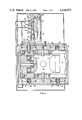
- FIG. 1shows a control arrangement associated with a transmission which is shown in cross-section
- FIG. 2shows a control arrangement for a particular application of the present invention
- FIG. 3is a view perpendicular to the view of FIG. 1 and containing the input and output shafts.
- such a transmissionconsists essentially of a housing 10 in which traction rollers 12 are disposed between, and in engagement with, coaxial toroidal discs 14 which are rotatably supported opposite one another on input and output shafts 13, 13' (FIG. 3) and which are forced into firm engagement with the traction rollers 12 with a force depending on the torque transmitted through the transmission.
- the traction rollers 12are supported by roller support structures 16, 17 which are pivotally supported by means of bearings 18 on tension sheets 19 which balance radial forces between the opposite support structures 16 and 17 and permit axial movement of the support structures 16, 17 to initiate a change of the transmission ratio.
- roller support structure 16Axially adjacent the support structures 16 and 17, the housing 10 is provided with cylinders 20, 21, 22 and 23 receiving control pistons 24, 25, 26 and 27 which are biased by springs 28 to abut the roller support structures 16 and 17 or are connected thereto.
- roller support structure 16has a rod 29 mounted thereon, which rod 29 extends through the piston 25 and through the housing 10 and carries a precess cam 30 provided with a transmission ratio precess cam surface 31.
- a master control valve 32Mounted on the housing 10 adjacent the precess cam 30 is a master control valve 32 which is a normal 4-way valve with an operating stem 33 disposed in a valve housing 34 and carrying a roller 35 biased by a spring 36 to abut the surface 31 of the precess cam 30.
- the master control valvehas associated therewith a pressurized fluid supply line 37 through which it receives pressurized fluid from a pressurized fluid source and pressurized fluid distribution lines 38 and 39 of which line 38 is connected to cylinders 20 and 22 and line 39 is connected to cylinders 21 and 23.
- the master control valve 32also has a fluid discharge line 40 which may lead to a fluid collection area or to lubrication points receiving the low pressure fluid discharged from the cylinders 20 to 23.
- all cylinders or pistonsare provided with small vents so arranged as to bleed off any gases. As shown in FIG.
- control valve 32may be slidably supported on a threaded support post 41 mounted on the housing 10 such that its position is adjustable by a ratio control knob 42 threaded onto the post 41.
- a relatively strong spring 43surrounds the post 41 and forces the valve housing into engagement with the control knob 42 so as to permit position control of the valve housing 34 by adjustment of the control knob 42.
- valve housing 34When the transmission ratio of the transmission is to be changed, the valve housing 34 is moved for example, axially against the force of the spring 43. The movement will provide for communication between the fluid supply line 37 and fluid distribution line 39 such that pressurized fluid is supplied to cylinders 21 and 23. At the same time the distribution line 38 is placed into communication with the discharge line 40 permitting discharge of fluid from the cylinders 20 and 22 thereby providing for axial precess movement of the roller support structures 16 and 17 in opposite directions. The roller support structure 16 is moved away from the control valve 32 and the control valve stem 33 follows the precess cam 30 moving with the roller support structure 16 until distribution line 39 is closed.
- the precess movement of the roller support structures 16 and 17causes the traction rollers 12 to walk to different circles of engagement with the respective toroidal discs 14 thereby changing the transmission ratio and pivoting the roller support structures 16 and 17.
- Rotation of the transmission in the proper predetermined directionwill cause pivoting of the roller support structure 16 in a direction such that the control valve roller 35 descends on the cam surface 31 or, rather, as pivoting to a different transmission ratio takes place, the traction roller support structure 16 is permitted to return to its normal neutral position, however at a different transmission ratio that is at a different contact position of the cam surface 31 with the control valve roller 35.
- each position of the control valve 32a corresponding pivot position of the roller support structures 16 and 17, that is a corresponding transmission ratio which can simply be set by adjusting the control valve position.
- the position of the control valve 32is adjustable by an adjusting knob 42.
- other meanssuch as a lever operating mechanism may be used.
- vacuum operated mechanismsmay be used for controlling the position of the master control valve 32.
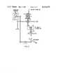
- FIG. 2An example for an automatic transmission control arrangement is given schematically in FIG. 2.
- engine intake manifold vacuum in combination with accelerator pedal positionis used to control the transmission ratio.
- Full opening of the carburetor throttle by stepping down on the accelerator pedal 51will bias the control valve 34 over modulating spring 52 into a speed-up direction.
- the vacuum in cylinder 53will collapse such that the piston spring 54 will first move the piston 55 against the modulating spring downwardly (as shown in FIG. 2) to change the transmission ratio for greater acceleration.
- the acceleratoris slowly released providing for even greater intake manifold vacuum and change of the transmission ratio in speed-up direction until a desired balance is reached.
- control arrangement as shownis mechanial to facilitate understanding of its operation. Modern technology however will easily substitute electronic components for the mechanical means described hereabove.
- a transmission ratio change with the traction roller transmission control described hereinis achieved simply by moving a master control valve structure provided with mechanical feedback means for determining execution of a desired transmission ratio change and insuring that the desired transmission ratio is maintained.
- a master control valve structureprovided with mechanical feedback means for determining execution of a desired transmission ratio change and insuring that the desired transmission ratio is maintained.
Landscapes
- Engineering & Computer Science (AREA)
- General Engineering & Computer Science (AREA)
- Mechanical Engineering (AREA)
- Friction Gearing (AREA)
- Control Of Transmission Device (AREA)
Abstract
Description
Claims (7)
Priority Applications (2)
| Application Number | Priority Date | Filing Date | Title |
|---|---|---|---|
| US06/301,442US4434675A (en) | 1981-09-11 | 1981-09-11 | Transmission ratio control arrangement for a precess cam controlled infinitely variable traction roller transmission |
| JP57156872AJPS5854262A (en) | 1981-09-11 | 1982-09-10 | Variable speed gear for traction roller non-stage transmission controlled by precess-cam |
Applications Claiming Priority (1)
| Application Number | Priority Date | Filing Date | Title |
|---|---|---|---|
| US06/301,442US4434675A (en) | 1981-09-11 | 1981-09-11 | Transmission ratio control arrangement for a precess cam controlled infinitely variable traction roller transmission |
Publications (1)
| Publication Number | Publication Date |
|---|---|
| US4434675Atrue US4434675A (en) | 1984-03-06 |
Family
ID=23163379
Family Applications (1)
| Application Number | Title | Priority Date | Filing Date |
|---|---|---|---|
| US06/301,442Expired - LifetimeUS4434675A (en) | 1981-09-11 | 1981-09-11 | Transmission ratio control arrangement for a precess cam controlled infinitely variable traction roller transmission |
Country Status (2)
| Country | Link |
|---|---|
| US (1) | US4434675A (en) |
| JP (1) | JPS5854262A (en) |
Cited By (32)
| Publication number | Priority date | Publication date | Assignee | Title |
|---|---|---|---|---|
| US4526051A (en)* | 1983-03-18 | 1985-07-02 | Excelermatic Inc. | Infinitely variable traction roller transmission speed control arrangement |
| US4537086A (en)* | 1983-02-21 | 1985-08-27 | Nippon Seiko Kabushiki Kaisha | Infinitely variable toric transmission |
| FR2567977A1 (en)* | 1984-07-20 | 1986-01-24 | Nippon Seiko Kk | TRANSMISSION REPORT CONTROL APPARATUS FOR INFINITELY VARIABLE TRANSMISSION OF THE TOROIDAL TYPE |
| US4572016A (en)* | 1981-12-14 | 1986-02-25 | Nippon Seiko Kabushiki Kaisha | Infinitely variable traction roller transmission |
| EP0172276A1 (en)* | 1983-01-03 | 1986-02-26 | Excelermatic Inc. | Hydraulically controlled infinitely variable traction roller transmission |
| US4576055A (en)* | 1984-08-15 | 1986-03-18 | Excelermatic, Inc. | Hydraulically controlled infinitely variable traction roller transmission |
| FR2570459A1 (en)* | 1984-09-14 | 1986-03-21 | Nippon Seiko Kk | TRANSMISSION ADJUSTING APPARATUS FOR INFINITELY VARIABLE TRANSMISSION |
| FR2571517A1 (en)* | 1984-08-28 | 1986-04-11 | Nippon Seiko Kk | TRANSMISSION CONTROL APPARATUS FOR INFINITELY VARIABLE TRANSMISSION, IN PARTICULAR AUTOMOTIVE |
| FR2578019A1 (en)* | 1985-02-28 | 1986-08-29 | Nippon Seiko Kk | TRANSMISSION CONTROL DRUM VALVE FOR INFINITELY VARIABLE TRACTION ROLLER TRANSMISSION OF THE TOROIDAL TYPE |
| US4905529A (en)* | 1986-11-20 | 1990-03-06 | Nissan Motor Co., Ltd. | Friction roller type continuously variable transmission |
| US4911030A (en)* | 1989-01-30 | 1990-03-27 | Excelermatic Inc. | Traction roller transmission ratio control arrangement |
| US4955246A (en)* | 1988-05-27 | 1990-09-11 | Nissan Motor Co., Ltd. | Continuously variable traction roller transmission |
| US4960004A (en)* | 1988-05-17 | 1990-10-02 | Nissan Motor Co., Ltd. | Continuously variable traction roller transmission |
| US5027669A (en)* | 1988-12-16 | 1991-07-02 | Nissan Motor Co., Ltd. | Dual toroidal cavity type continuously variable transmission |
| EP0373649A3 (en)* | 1988-12-16 | 1991-07-03 | Nissan Motor Co., Ltd. | Shift control system for a toroidal type continuously variable transmission |
| US5099710A (en)* | 1988-12-16 | 1992-03-31 | Nissan Motor Co., Ltd. | Continuously variable transmission system having parallel drive paths with fluid control valve including pressure equalization |
| EP0415391A3 (en)* | 1989-08-30 | 1993-03-03 | Nissan Motor Co., Ltd. | Ratio control system for toroidal continuously variable transmission |
| US5212997A (en)* | 1991-06-12 | 1993-05-25 | Nissan Motor Co., Ltd. | Friction roller type continuously variable transmission |
| US5242337A (en)* | 1989-11-03 | 1993-09-07 | Torotrak (Development) Limited | Continuously-variable-ratio transmissions of the toroidal-race rolling-traction type |
| US5330396A (en)* | 1992-12-16 | 1994-07-19 | The Torax Company, Inc. | Loading device for continuously variable transmission |
| US5540631A (en)* | 1992-12-16 | 1996-07-30 | The Torax Company, Inc. | Continuously variable transmission with a hydraulic control system |
| DE19644958A1 (en)* | 1995-10-30 | 1997-05-07 | Nissan Motor | Infinitely variable ratio power transmission |
| US5674145A (en)* | 1995-04-24 | 1997-10-07 | Nissan Motor Co., Ltd. | Shift control system for troidal continuously variable transmission |
| US5681236A (en)* | 1995-02-27 | 1997-10-28 | Isuzu Motors Limited | Toroidal continuous variable transmission |
| US5895337A (en)* | 1995-03-16 | 1999-04-20 | Torotrak (Development) Limited | Continuously-variable-ratios transmissions |
| EP0967413A1 (en)* | 1998-06-22 | 1999-12-29 | Nissan Motor Co., Ltd. | Toroidal continuously variable transmission |
| US6036617A (en)* | 1997-11-13 | 2000-03-14 | Nissan Motor Co., Ltd. | Continuously variable transmission, and controller and control method thereof |
| DE19930375C2 (en)* | 1998-07-02 | 2002-05-23 | Nissan Motor | Infinitely adjustable toroidal gear |
| US6488607B1 (en)* | 1999-07-12 | 2002-12-03 | Nsk Ltd. | Toroidal type continuously variable transmission |
| DE10135900A1 (en)* | 2001-07-24 | 2003-02-06 | Zahnradfabrik Friedrichshafen | Adjusting device for tilt of friction wheel of continuously variable friction gear has roller on edge of lever arm so that constant line contact between lever arm and ramp-form section of control plate is ensured |
| US20050133304A1 (en)* | 1991-10-23 | 2005-06-23 | Viken James P. | Fluid exchange system for vehicles |
| US20100197447A1 (en)* | 2007-02-21 | 2010-08-05 | Brian Donohoe | Continuously variable transmission |
Families Citing this family (6)
| Publication number | Priority date | Publication date | Assignee | Title |
|---|---|---|---|---|
| JPS61119866A (en)* | 1984-11-15 | 1986-06-07 | Daihatsu Motor Co Ltd | Toroidal type continuously variable transmission |
| JPS61124753A (en)* | 1984-11-17 | 1986-06-12 | Daihatsu Motor Co Ltd | Control valve |
| JPS61197850A (en)* | 1985-02-28 | 1986-09-02 | Nippon Seiko Kk | Spool valve device for shifting of toroidal type continuously variable transmission |
| JPS6237562A (en)* | 1985-08-12 | 1987-02-18 | Nippon Seiko Kk | Shift holding device for toroidal continuously variable transmission |
| DE3711744A1 (en)* | 1987-04-07 | 1988-10-27 | Bosch Gmbh Robert | METHOD AND DEVICE FOR CONTROLLING THE FUEL INJECTION AMOUNT |
| JP2725488B2 (en)* | 1991-07-04 | 1998-03-11 | 日産自動車株式会社 | Friction wheel type continuously variable transmission |
Citations (10)
| Publication number | Priority date | Publication date | Assignee | Title |
|---|---|---|---|---|
| US3048047A (en) | 1961-03-08 | 1962-08-07 | Curtiss Wright Corp | Toroidal transmission damping mechanism |
| DE1197714B (en) | 1961-01-30 | 1965-07-29 | Karl Maichen | Tapered friction gear with rotating tapered rollers |
| US3810398A (en) | 1972-11-16 | 1974-05-14 | Tracor | Toric transmission with hydraulic controls and roller damping means |
| US3828618A (en) | 1971-07-27 | 1974-08-13 | Rotax Ltd | Constant speed hydraulically controlled toric transmission with concentric, two piston valve, governor and constant ratio means |
| US4056989A (en) | 1976-05-28 | 1977-11-08 | Caterpillar Tractor Co. | Vehicle drive |
| US4086820A (en) | 1976-06-25 | 1978-05-02 | Excelermatic, Inc. | Infinitely variable traction roller transmission |
| US4126052A (en) | 1975-12-11 | 1978-11-21 | Jackman Charles W | Friction transmission |
| US4275610A (en) | 1979-02-08 | 1981-06-30 | Excelermatic Inc. | Infinitely variable traction roller transmission |
| GB2033507B (en) | 1978-10-17 | 1982-12-22 | Cam Gears Ltd | Friction drive assembly |
| GB2035481B (en) | 1978-11-16 | 1983-01-19 | Cam Gears Ltd | Speed control systems |
- 1981
- 1981-09-11USUS06/301,442patent/US4434675A/ennot_activeExpired - Lifetime
- 1982
- 1982-09-10JPJP57156872Apatent/JPS5854262A/enactiveGranted
Patent Citations (10)
| Publication number | Priority date | Publication date | Assignee | Title |
|---|---|---|---|---|
| DE1197714B (en) | 1961-01-30 | 1965-07-29 | Karl Maichen | Tapered friction gear with rotating tapered rollers |
| US3048047A (en) | 1961-03-08 | 1962-08-07 | Curtiss Wright Corp | Toroidal transmission damping mechanism |
| US3828618A (en) | 1971-07-27 | 1974-08-13 | Rotax Ltd | Constant speed hydraulically controlled toric transmission with concentric, two piston valve, governor and constant ratio means |
| US3810398A (en) | 1972-11-16 | 1974-05-14 | Tracor | Toric transmission with hydraulic controls and roller damping means |
| US4126052A (en) | 1975-12-11 | 1978-11-21 | Jackman Charles W | Friction transmission |
| US4056989A (en) | 1976-05-28 | 1977-11-08 | Caterpillar Tractor Co. | Vehicle drive |
| US4086820A (en) | 1976-06-25 | 1978-05-02 | Excelermatic, Inc. | Infinitely variable traction roller transmission |
| GB2033507B (en) | 1978-10-17 | 1982-12-22 | Cam Gears Ltd | Friction drive assembly |
| GB2035481B (en) | 1978-11-16 | 1983-01-19 | Cam Gears Ltd | Speed control systems |
| US4275610A (en) | 1979-02-08 | 1981-06-30 | Excelermatic Inc. | Infinitely variable traction roller transmission |
Cited By (37)
| Publication number | Priority date | Publication date | Assignee | Title |
|---|---|---|---|---|
| US4572016A (en)* | 1981-12-14 | 1986-02-25 | Nippon Seiko Kabushiki Kaisha | Infinitely variable traction roller transmission |
| EP0172276A1 (en)* | 1983-01-03 | 1986-02-26 | Excelermatic Inc. | Hydraulically controlled infinitely variable traction roller transmission |
| US4537086A (en)* | 1983-02-21 | 1985-08-27 | Nippon Seiko Kabushiki Kaisha | Infinitely variable toric transmission |
| US4526051A (en)* | 1983-03-18 | 1985-07-02 | Excelermatic Inc. | Infinitely variable traction roller transmission speed control arrangement |
| FR2567977A1 (en)* | 1984-07-20 | 1986-01-24 | Nippon Seiko Kk | TRANSMISSION REPORT CONTROL APPARATUS FOR INFINITELY VARIABLE TRANSMISSION OF THE TOROIDAL TYPE |
| US4576055A (en)* | 1984-08-15 | 1986-03-18 | Excelermatic, Inc. | Hydraulically controlled infinitely variable traction roller transmission |
| FR2571517A1 (en)* | 1984-08-28 | 1986-04-11 | Nippon Seiko Kk | TRANSMISSION CONTROL APPARATUS FOR INFINITELY VARIABLE TRANSMISSION, IN PARTICULAR AUTOMOTIVE |
| FR2570459A1 (en)* | 1984-09-14 | 1986-03-21 | Nippon Seiko Kk | TRANSMISSION ADJUSTING APPARATUS FOR INFINITELY VARIABLE TRANSMISSION |
| FR2578019A1 (en)* | 1985-02-28 | 1986-08-29 | Nippon Seiko Kk | TRANSMISSION CONTROL DRUM VALVE FOR INFINITELY VARIABLE TRACTION ROLLER TRANSMISSION OF THE TOROIDAL TYPE |
| US4718294A (en)* | 1985-02-28 | 1988-01-12 | Nippon Seiko Kabushiki Kaisha | Ratio control spool valve for a toroidal type infinitely variable traction roller transmission |
| US4905529A (en)* | 1986-11-20 | 1990-03-06 | Nissan Motor Co., Ltd. | Friction roller type continuously variable transmission |
| US4960004A (en)* | 1988-05-17 | 1990-10-02 | Nissan Motor Co., Ltd. | Continuously variable traction roller transmission |
| US4955246A (en)* | 1988-05-27 | 1990-09-11 | Nissan Motor Co., Ltd. | Continuously variable traction roller transmission |
| US5027669A (en)* | 1988-12-16 | 1991-07-02 | Nissan Motor Co., Ltd. | Dual toroidal cavity type continuously variable transmission |
| EP0373649A3 (en)* | 1988-12-16 | 1991-07-03 | Nissan Motor Co., Ltd. | Shift control system for a toroidal type continuously variable transmission |
| US5052236A (en)* | 1988-12-16 | 1991-10-01 | Nissan Motor Co., Ltd. | Forward and reverse hydraulic control for toroidal continuously variable transmission |
| US5099710A (en)* | 1988-12-16 | 1992-03-31 | Nissan Motor Co., Ltd. | Continuously variable transmission system having parallel drive paths with fluid control valve including pressure equalization |
| US4911030A (en)* | 1989-01-30 | 1990-03-27 | Excelermatic Inc. | Traction roller transmission ratio control arrangement |
| EP0415391A3 (en)* | 1989-08-30 | 1993-03-03 | Nissan Motor Co., Ltd. | Ratio control system for toroidal continuously variable transmission |
| US5242337A (en)* | 1989-11-03 | 1993-09-07 | Torotrak (Development) Limited | Continuously-variable-ratio transmissions of the toroidal-race rolling-traction type |
| US5212997A (en)* | 1991-06-12 | 1993-05-25 | Nissan Motor Co., Ltd. | Friction roller type continuously variable transmission |
| US20050133304A1 (en)* | 1991-10-23 | 2005-06-23 | Viken James P. | Fluid exchange system for vehicles |
| US5330396A (en)* | 1992-12-16 | 1994-07-19 | The Torax Company, Inc. | Loading device for continuously variable transmission |
| US5417620A (en)* | 1992-12-16 | 1995-05-23 | The Torax Company, Inc. | Loading device for continuously variable transmission |
| US5540631A (en)* | 1992-12-16 | 1996-07-30 | The Torax Company, Inc. | Continuously variable transmission with a hydraulic control system |
| US5681236A (en)* | 1995-02-27 | 1997-10-28 | Isuzu Motors Limited | Toroidal continuous variable transmission |
| US5895337A (en)* | 1995-03-16 | 1999-04-20 | Torotrak (Development) Limited | Continuously-variable-ratios transmissions |
| US5674145A (en)* | 1995-04-24 | 1997-10-07 | Nissan Motor Co., Ltd. | Shift control system for troidal continuously variable transmission |
| DE19644958C2 (en)* | 1995-10-30 | 2003-04-10 | Nissan Motor | Gearbox with continuously adjustable transmission ratio |
| DE19644958A1 (en)* | 1995-10-30 | 1997-05-07 | Nissan Motor | Infinitely variable ratio power transmission |
| US6036617A (en)* | 1997-11-13 | 2000-03-14 | Nissan Motor Co., Ltd. | Continuously variable transmission, and controller and control method thereof |
| EP0967413A1 (en)* | 1998-06-22 | 1999-12-29 | Nissan Motor Co., Ltd. | Toroidal continuously variable transmission |
| US6159126A (en)* | 1998-06-22 | 2000-12-12 | Nissan Motor Co., Ltd. | Toroidal continuously variable transmission |
| DE19930375C2 (en)* | 1998-07-02 | 2002-05-23 | Nissan Motor | Infinitely adjustable toroidal gear |
| US6488607B1 (en)* | 1999-07-12 | 2002-12-03 | Nsk Ltd. | Toroidal type continuously variable transmission |
| DE10135900A1 (en)* | 2001-07-24 | 2003-02-06 | Zahnradfabrik Friedrichshafen | Adjusting device for tilt of friction wheel of continuously variable friction gear has roller on edge of lever arm so that constant line contact between lever arm and ramp-form section of control plate is ensured |
| US20100197447A1 (en)* | 2007-02-21 | 2010-08-05 | Brian Donohoe | Continuously variable transmission |
Also Published As
| Publication number | Publication date |
|---|---|
| JPS5854262A (en) | 1983-03-31 |
| JPH0247627B2 (en) | 1990-10-22 |
Similar Documents
| Publication | Publication Date | Title |
|---|---|---|
| US4434675A (en) | Transmission ratio control arrangement for a precess cam controlled infinitely variable traction roller transmission | |
| US4369675A (en) | Method and apparatus for controlling an infinitely variable transmission of a motor vehicle | |
| US3596528A (en) | Infinitely variable cone pulley transmission | |
| US4522086A (en) | Control system for continuously variable transmission | |
| US4091690A (en) | Method for controlling continuously variable drive ratio transmissions and a system therefor | |
| EP0051918B1 (en) | Variable-ratio drive mechanisms | |
| US4960004A (en) | Continuously variable traction roller transmission | |
| EP0291061B1 (en) | Method of and apparatus for controlling the transmisson ratio of a continuously variable transmission | |
| EP1085241A2 (en) | Hydraulic control for a continuously variable transmission | |
| US5083473A (en) | Ratio control system for toroidal continuously variable transmission | |
| US6287232B1 (en) | Non-finite speed ratio continuously variable transmission device | |
| JPS6252176B2 (en) | ||
| US3886819A (en) | Transmission shift control | |
| US4526051A (en) | Infinitely variable traction roller transmission speed control arrangement | |
| JPH0122503B2 (en) | ||
| JPH023071B2 (en) | ||
| US4718294A (en) | Ratio control spool valve for a toroidal type infinitely variable traction roller transmission | |
| US3952714A (en) | Link length adjusting apparatus | |
| EP1092895A2 (en) | Toroidal continuously-variable transmissions | |
| US4872377A (en) | Transmission ratio control system for a continuously variable transmission | |
| US4977798A (en) | Transmission ratio control system for a continuously variable transmission | |
| US6656081B2 (en) | Ratio control for toroidal-type traction drive incorporating lost motion cam actuator | |
| US4760867A (en) | Pressure modulator valve device | |
| KR950010689B1 (en) | Control of continuously variable transmission | |
| US4554841A (en) | Speed control device of a toric type infinitely variable transmission |
Legal Events
| Date | Code | Title | Description |
|---|---|---|---|
| AS | Assignment | Owner name:EXCELERMATIC, INC., A CORP. OF DE. Free format text:ASSIGNMENT OF ASSIGNORS INTEREST.;ASSIGNOR:KRAUS, CHARLES E.;REEL/FRAME:003921/0207 Effective date:19810901 | |
| STCF | Information on status: patent grant | Free format text:PATENTED CASE | |
| MAFP | Maintenance fee payment | Free format text:PAYMENT OF MAINTENANCE FEE, 4TH YEAR, PL 96-517 (ORIGINAL EVENT CODE: M170); ENTITY STATUS OF PATENT OWNER: LARGE ENTITY Year of fee payment:4 | |
| MAFP | Maintenance fee payment | Free format text:PAYMENT OF MAINTENANCE FEE, 8TH YEAR, PL 96-517 (ORIGINAL EVENT CODE: M171); ENTITY STATUS OF PATENT OWNER: LARGE ENTITY Year of fee payment:8 | |
| AS | Assignment | Owner name:NSK, LTD., A CORP. OF JAPAN, JAPAN Free format text:ASSIGNMENT OF ASSIGNORS INTEREST.;ASSIGNOR:EXCELERMATIC INC.;REEL/FRAME:005935/0329 Effective date:19911008 | |
| FEPP | Fee payment procedure | Free format text:PAYER NUMBER DE-ASSIGNED (ORIGINAL EVENT CODE: RMPN); ENTITY STATUS OF PATENT OWNER: LARGE ENTITY Free format text:PAYOR NUMBER ASSIGNED (ORIGINAL EVENT CODE: ASPN); ENTITY STATUS OF PATENT OWNER: LARGE ENTITY | |
| FEPP | Fee payment procedure | Free format text:PAYOR NUMBER ASSIGNED (ORIGINAL EVENT CODE: ASPN); ENTITY STATUS OF PATENT OWNER: LARGE ENTITY Free format text:PAYER NUMBER DE-ASSIGNED (ORIGINAL EVENT CODE: RMPN); ENTITY STATUS OF PATENT OWNER: LARGE ENTITY | |
| MAFP | Maintenance fee payment | Free format text:PAYMENT OF MAINTENANCE FEE, 12TH YEAR, LARGE ENTITY (ORIGINAL EVENT CODE: M185); ENTITY STATUS OF PATENT OWNER: LARGE ENTITY Year of fee payment:12 | |
| FEPP | Fee payment procedure | Free format text:PAT HLDR NO LONGER CLAIMS SMALL ENT STAT AS SMALL BUSINESS (ORIGINAL EVENT CODE: LSM2); ENTITY STATUS OF PATENT OWNER: LARGE ENTITY |