US4434489A - Automatic test systems - Google Patents
Automatic test systemsDownload PDFInfo
- Publication number
- US4434489A US4434489AUS06/310,869US31086981AUS4434489AUS 4434489 AUS4434489 AUS 4434489AUS 31086981 AUS31086981 AUS 31086981AUS 4434489 AUS4434489 AUS 4434489A
- Authority
- US
- United States
- Prior art keywords
- displayed
- circuit
- faults
- component
- component part
- Prior art date
- Legal status (The legal status is an assumption and is not a legal conclusion. Google has not performed a legal analysis and makes no representation as to the accuracy of the status listed.)
- Expired - Lifetime
Links
- 238000012360testing methodMethods0.000titleclaimsabstractdescription40
- 230000008439repair processEffects0.000claimsabstractdescription37
- 239000004020conductorSubstances0.000claimsdescription13
- 230000003287optical effectEffects0.000claimsdescription11
- 239000003990capacitorSubstances0.000claimsdescription4
- 230000000007visual effectEffects0.000description10
- 238000010586diagramMethods0.000description4
- 230000007246mechanismEffects0.000description3
- 239000003086colorantSubstances0.000description2
- 238000011960computer-aided designMethods0.000description2
- 238000012937correctionMethods0.000description2
- 230000001360synchronised effectEffects0.000description2
- 208000036693Color-vision diseaseDiseases0.000description1
- 230000005540biological transmissionEffects0.000description1
- 201000007254color blindnessDiseases0.000description1
- 238000013497data interchangeMethods0.000description1
- 230000007547defectEffects0.000description1
- 230000009977dual effectEffects0.000description1
- 230000000694effectsEffects0.000description1
- 238000004519manufacturing processMethods0.000description1
- 238000000926separation methodMethods0.000description1
Images


Classifications
- G—PHYSICS
- G01—MEASURING; TESTING
- G01R—MEASURING ELECTRIC VARIABLES; MEASURING MAGNETIC VARIABLES
- G01R31/00—Arrangements for testing electric properties; Arrangements for locating electric faults; Arrangements for electrical testing characterised by what is being tested not provided for elsewhere
- G01R31/28—Testing of electronic circuits, e.g. by signal tracer
- G01R31/2801—Testing of printed circuits, backplanes, motherboards, hybrid circuits or carriers for multichip packages [MCP]
- G01R31/2806—Apparatus therefor, e.g. test stations, drivers, analysers, conveyors
- Y—GENERAL TAGGING OF NEW TECHNOLOGICAL DEVELOPMENTS; GENERAL TAGGING OF CROSS-SECTIONAL TECHNOLOGIES SPANNING OVER SEVERAL SECTIONS OF THE IPC; TECHNICAL SUBJECTS COVERED BY FORMER USPC CROSS-REFERENCE ART COLLECTIONS [XRACs] AND DIGESTS
- Y10—TECHNICAL SUBJECTS COVERED BY FORMER USPC
- Y10S—TECHNICAL SUBJECTS COVERED BY FORMER USPC CROSS-REFERENCE ART COLLECTIONS [XRACs] AND DIGESTS
- Y10S345/00—Computer graphics processing and selective visual display systems
- Y10S345/904—Display with fail/safe testing feature
Definitions
- This inventionrelates to automatic testing systems for use in the automatic diagnoses of faults in electronic circuits such as printed circuit boards bearing electrical components, either following manufacture or following service during which faults have developed.
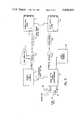
- FIG. 1 of the accompanying drawingsis a block schematic diagram.
- a printed circuit board having mounted thereon electrical components (which are not separately shown) and to be testedis represented at 1.
- an automatic test apparatus 2which is in fact a proprietary machine marketed by Marconi Instruments Limited under the trade name "Autotest System 80". It will not be necessary to describe the automatic testing machine in detail but in essence it is mechanically similar to the machine described in the specification of our U.K. Pat. No. 1,530,350.
- the visual display unit 3will in operation display such information as "R 14 1.02K H" or "short 100 101". This information conveys to the operator that resistor R14 in the circuit has a value of 1.02K ⁇ which is high or above tolerance and that a short circuit is apparent at a position identified by the positional reference numbers 100 and 101. Whilst examples of only two faults are given, obviously in any given case a greater number of faults may be displayed on the visual display unit 3.
- the operatormay then enter, by means of the keyboard of the visual display unit 3, the serial number of the printed circuit board 1 under test and obtain a print-out showing all of the faults diagnosed in that particular printed circuit board.
- the serial number(represented at 4) may be provided not only in conventional numeric form but also in the form of bar code which is read by an optical reader 5.
- the block 6represents a suitable interface e.g. a Type 9300 interface manufactured by Interface Mechanisms Inc of USA.
- the systemconstitutes an automatic test system which is as well known per se.
- Such a systemis capable of performing automatic tests at a relatively high rate and in practice it is difficult to provide a repair facility which is capable of keeping up with the correction of faults diagnosed by the apparatus.
- One object of the present inventionis to provide an automatic test system having a repair facility which eases the task of a repairer in identifying the positions and nature of faults diagnosed by the apparatus whereby to improve the general efficiency with which repairs or corrections may be made.
- an automatic test systemfor testing and diagnosing faults in an electronic circuit, such as a printed circuit board carrying electronic components, comprises an automatic test apparatus provided to receive said circuit and produce signals indicative of faults therein, means for transmitting said signals to a repair station, means at said repair station for storing data enabling a display consisting of individual component parts of said circuit to be displayed on a display device and means responsive to said fault indicative signals for selecting an appropriate portion of said stored data to cause a component part of said circuit to be displayed on said display device, corresponding to an actual component part of said circuit wherein a fault lies, in a fashion in which said displayed component part visually stands out.
- the arrangement by which said displayed component part is displayed in a fashion in which it visually stands outis such that only actual component parts which are faulty are displayed.
- the arrangement by which said displayed component part is displayed in a fashion in which it visually stands outis such that actual component parts which are faulty are displayed in one colour whilst actual component parts which are not faulty are displayed in another colour.
- the arrangementis such that under control of a repairer/operator at said repair station one after another of those component parts of said circuit wherein faults lie may be caused to be displayed in their relative positions on said display device.
- the arrangementis such that in addition to a component part or component parts of said circuit being displayed an outline corresponding to the outline of said circuit is also displayed in order to assist a repairer/operator to locate the position of the component part being displayed.
- said outlineis displayed in a colour which contrasts with the remainder of the display.
- said stored datais such that a repairer/operator may control the display to provide a view as seen from above or below said circuit.
- said displayprovides, in superimposed fashion, views as seen from above and below said circuit with corresponding parts of the two views being in the same colour but of a different shade or hue.
- Each component part of said circuitis preferably an individual electronic component such as a resistor or a capacitor, or a portion of the circuit conductors. Where a component part of said circuit is displayed which consists of a portion of the circuit conductors this will represent the circuit configuration in the immediate vicinity of a fault such as an open circuit or short circuit.
- said last mentioned meanscomprises means for adding to a batch of signals indicative of faults transmitted by said automatic test apparatus a code representing a serial number of a tested electronic circuit.
- said last mentioned meanscomprises an optical reader provided to read a bar code associated with an electronic circuit under test in which case at said repair station an optical reader may also be provided for reading bar codes associated with electronic circuits for repair whereby the appropriate batch of fault indicative signals stored at said repair station may be called up.
- the display device at said repair stationis also arranged to provide readable information concerning the nature of said component part such as the value, tolerance and/or stores part-number of an electronic component such as a resistor or a capacitor.
- FIG. 1is a block diagram of a prior art automatic test system for printed circuit boards.
- FIG. 2is a block diagram of an automatic test system having a repair facility in accordance with the present invention
- FIG. 2Aillustrates the Graphics Display Unit 14 in FIG. 2 with a different display.
- FIG. 3is a block diagram of another embodiment of an automatic test system having a repair facility according to the present invention.
- the automatic test systemitself is the same as that described with reference to FIG. 1.
- the automatic test machine 2is provided to apply fault identifying signals not only to the visual display unit 3 but also via a synchronised serial data link 7 to a repair station terminal 8 which may be located at any convenient remote point.
- the repair station terminal 8consists of a general purpose interface bus controller (Marconi Instruments Type TK1802) together with a graphics terminal.
- the controller within 8is connected to a dual floppy disc drive system 10 (Marconi Instruments Type TK1862/1) which is arranged to provide buffer storage on floppy discs of (a) the serial number of a printed circuit board such as 1 tested and (b) the faults located during such test. Storage is also provided relating to the circuit layout and component location of the printed circuit board such as 1 being tested, viewed from above or below.
- a dual floppy disc drive system 10Marconi Instruments Type TK1862/1
- Storageis also provided relating to the circuit layout and component location of the printed circuit board such as 1 being tested, viewed from above or below.
- an optical reader 11Provided to read the bar code serial number of a faulty printed circuit board presented for repair (and represented at 1.f) is an optical reader 11.
- the output of the optical code reader 11is connected via a suitable interface 12 (again Type 9300 manufactured by Interface Mechanisms Inc) to the controller within 8.
- the interface 12also connects a visual display unit 13 by means of which the repairer/operator may select in turn each fault diagnosed in connection with the board identifed by the bar code read by the optical reader 11.
- a graphics display unit 14Connected to the graphics terminal of 8 is a graphics display unit 14.
- the unit 14is required only to be used in a display mode but in practice a conventional graphics display unit such as the Tektronix Type 4025 with its remaining functions ignored.
- the calling up of each faultin turn produces from the stored information on the floppy discs in the disc drive unit 10 a display such as that represented in the drawing within the block 14.
- the information displayconsists of an outline 15 of the circuit board 1.f. and within that outline a representation 16 of the faulty component causing the fault. This representation is shown in a position corresponding to that which the actual component occupies on the printed circuit board 1.f. This enables the repairer quickly and speedily to locate the faulty component on the actual board 1.f. Should the repairer require, the display on the unit 14 may be caused to represent the position of the faulty component 16 as viewed from the underside of the board, by virtue of the alternative information stored on the floppy discs.
- the resistoris R12 its nominal value is 10K ⁇ and its tolerance is 5%.
- the repairer/operatormay then, by means of the keyboard of the visual display unit 13, command that the next fault be displayed and again a display appears upon the screen of the graphics display unit 14 which shows only that faulty component within the outline 15 of the printed circuit board with again any identifying matter which may be required outside of that outline.
- the display presented to the repairer/operator in connection with that particular block on the screen of the VDUconsists of a representation of the conductors in the immediate locality of the short circuit or open circuit and in relative position compared to the actual position of the fault on the board so that again the repairer is assisted in identifying the position of the fault.
- FIG. 2AOne example of this is illustrated in FIG. 2A.
- the repairer/operatormay enter the serial number of the board by means of the keyboard of the visual display unit 13 in order to identify the particular board which is to be repaired.
- the automatic test systemitself is again the same as that described with reference to FIG. 1.
- the automatic test machine 2is provided to apply fault identifying signals not only to the visual display unit 3 but also via a synchronised serial data link 7 to a repair station terminal 8 which may be located at any convenient remote point.
- the repair station terminalconsists of a micro-computer 17 (DEC LS1-11/23) which controls its activities and a colour graphics terminal 22 together with storage provided by a disc 18 (71/2 MByte Winchester disc) which also serves as the system disc containing the executive software. Also included is a floppy disc drive 19 which provides an exchangeable medium for back-up storage and data interchange.
- a micro-computer 17DEC LS1-11/23 which controls its activities and a colour graphics terminal 22 together with storage provided by a disc 18 (71/2 MByte Winchester disc) which also serves as the system disc containing the executive software.
- a floppy disc drive 19which provides an exchangeable medium for back-up storage and data interchange.
- the fault data from the automatic testing station 2is transmitted to the repair station where it is recorded on disc, together with the serial number of the board that has been examined. Also stored on the disc 18 are data files containing information relating to the broad outline of the board, the layout of the conductors and the arrangement and shape of the components for the printed circuit board that is being tested.
- the board descriptor filescan be entered manually or using automatic generation from CAD (Computer Aided Design) systems.
- optical reader 20Provided to read the bar code serial number of a faulty printed circuit board presented for repair (and represented at 1.f.) is an optical reader 20.
- the output of the optical code reader 20is connected via a suitable interface 12 (again Type 9300 manufactured by Interface Mechanisms Inc) to the micro-computer. This is connected to a colour graphics terminal 22 which enables the repairer/operator to select in turn each fault diagnosed in connection with the board identified by the bar code read by the optical reader 20.
- the micro-computer 17which controls the acquisition and storage of test results also responds to the operator's request for fault data on particular boards.
- These two time-shared functionsare scheduled on a foreground/background basis i.e. the background function is only given processor time when time is not required for the foreground function.
- the foreground taskis that of acquiring the test results, checking them for correct format and attending to data transmission protocols.
- the background functionis that of searching for fault data for a specified board when requested by the repairer/operator.
- the coloursare chosen to give greatest contrast and reduce confusion caused by the more common types of colour-blindness.
- the displaycan be updated to show the next one by operating a single key.
- a fault summaryis maintained on the character display which gives overall details of all the faults on the board under repair, and also a warning if the board has circulated around the repair route a number of times.
- the repairer/operatormay enter the serial number of the board by means of the keyboard of the visual display unit 13 in order to identify the particular board which is to be repaired.
Landscapes
- Engineering & Computer Science (AREA)
- Computer Hardware Design (AREA)
- Microelectronics & Electronic Packaging (AREA)
- General Engineering & Computer Science (AREA)
- Physics & Mathematics (AREA)
- General Physics & Mathematics (AREA)
- Testing Electric Properties And Detecting Electric Faults (AREA)
- Tests Of Electronic Circuits (AREA)
Abstract
Description
Claims (14)
Applications Claiming Priority (4)
| Application Number | Priority Date | Filing Date | Title |
|---|---|---|---|
| GB8033007 | 1980-10-13 | ||
| GB8033007 | 1980-10-13 | ||
| GB8129277AGB2086061B (en) | 1980-10-13 | 1981-09-28 | Automatic test systems |
| GB8129277 | 1981-09-28 |
Publications (1)
| Publication Number | Publication Date |
|---|---|
| US4434489Atrue US4434489A (en) | 1984-02-28 |
Family
ID=26277200
Family Applications (1)
| Application Number | Title | Priority Date | Filing Date |
|---|---|---|---|
| US06/310,869Expired - LifetimeUS4434489A (en) | 1980-10-13 | 1981-10-13 | Automatic test systems |
Country Status (4)
| Country | Link |
|---|---|
| US (1) | US4434489A (en) |
| EP (1) | EP0050014B1 (en) |
| DE (1) | DE3168922D1 (en) |
| GB (1) | GB2086061B (en) |
Cited By (38)
| Publication number | Priority date | Publication date | Assignee | Title |
|---|---|---|---|---|
| US4594677A (en)* | 1983-11-09 | 1986-06-10 | International Business Machines Corporation | System for detecting and diagnosing noise caused by simultaneous current switching |
| US4654852A (en)* | 1984-05-15 | 1987-03-31 | International Business Machines Corporation | On-line problem-determination procedure for diagnosis of faults in a data-processing system |
| US4713815A (en)* | 1986-03-12 | 1987-12-15 | International Business Machines Corp. | Automatic fault location system for electronic devices |
| US4766595A (en)* | 1986-11-26 | 1988-08-23 | Allied-Signal Inc. | Fault diagnostic system incorporating behavior models |
| US4829520A (en)* | 1987-03-16 | 1989-05-09 | American Telephone And Telegraph Company, At&T Bell Laboratories | In-place diagnosable electronic circuit board |
| US4841456A (en)* | 1986-09-09 | 1989-06-20 | The Boeing Company | Test system and method using artificial intelligence control |
| US4872167A (en)* | 1986-04-01 | 1989-10-03 | Hitachi, Ltd. | Method for displaying program executing circumstances and an apparatus using the same |
| US4912711A (en)* | 1987-01-26 | 1990-03-27 | Nec Corporation | Diagnosing apparatus capable of readily diagnosing failures of a computer system |
| US4916699A (en)* | 1987-03-10 | 1990-04-10 | Sharp Kabushiki Kaisha | Diagnostic data processing system with selective touch-sensitive display |
| US5003251A (en)* | 1989-09-12 | 1991-03-26 | Grumman Aerospace Corporation | Bar code reader for printed circuit board |
| US5010551A (en)* | 1989-04-14 | 1991-04-23 | Xerox Corporation | Self contained troubleshooting aid for declared and non declared machine problems |
| US5224055A (en)* | 1989-02-10 | 1993-06-29 | Plessey Semiconductors Limited | Machine for circuit design |
| US5280251A (en)* | 1991-11-07 | 1994-01-18 | Cami Research, Inc. | Continuity analysis system with graphic wiring display |
| US5291590A (en)* | 1990-07-13 | 1994-03-01 | Fujitsu Limited | Method of detecting and processing abnormal message output from computer system and detecting and processing apparatus therefor |
| US5297256A (en)* | 1986-04-07 | 1994-03-22 | Crosfield Electronics (Usa) Limited | Digital image processing system and method |
| US5351247A (en)* | 1988-12-30 | 1994-09-27 | Digital Equipment Corporation | Adaptive fault identification system |
| US5390325A (en)* | 1992-12-23 | 1995-02-14 | Taligent, Inc. | Automated testing system |
| US5414712A (en)* | 1991-07-23 | 1995-05-09 | Progressive Computing, Inc. | Method for transmitting data using a communication interface box |
| US5588109A (en)* | 1995-01-23 | 1996-12-24 | Hewlett-Packard Company | User interface for a remote diagnostic device |
| WO1997016742A1 (en)* | 1995-11-02 | 1997-05-09 | Genrad, Inc. | Conditionally generating test instructions depending on device defect data |
| US5696450A (en)* | 1994-08-19 | 1997-12-09 | Fujitsu General Limited | Automatic safety test equipment for printed circuit board |
| US5819028A (en)* | 1992-06-10 | 1998-10-06 | Bay Networks, Inc. | Method and apparatus for determining the health of a network |
| US5831854A (en)* | 1995-01-17 | 1998-11-03 | Omron Corporation | Method and device for supporting the repair of defective substrates |
| US6003081A (en)* | 1998-02-17 | 1999-12-14 | International Business Machines Corporation | Data processing system and method for generating a detailed repair request for a remote client computer system |
| US6246334B1 (en)* | 1999-04-26 | 2001-06-12 | Dialogic Corporation | Board ID display system |
| US6467153B2 (en)* | 1997-06-11 | 2002-10-22 | Western Digital Technologies, Inc. | Method for manufacturing a disk drive |
| WO2004017081A1 (en)* | 2002-08-16 | 2004-02-26 | Crc Group Plc | Electronic circuit testing method and apparatus |
| US20040179413A1 (en)* | 2003-03-10 | 2004-09-16 | Yung-Chien Lee | Automated test method |
| US20050091178A1 (en)* | 2001-06-13 | 2005-04-28 | Masayuki Inoue | Inspection state check system |
| US20050216326A1 (en)* | 2001-06-13 | 2005-09-29 | Honda Giken Kogyo Kabushiki Kaisha | Mechanic skill control system |
| US20060156141A1 (en)* | 2004-12-07 | 2006-07-13 | Ouchi Norman K | Defect symptom repair system and methods |
| US20070044957A1 (en)* | 2005-05-27 | 2007-03-01 | Oil Sands Underground Mining, Inc. | Method for underground recovery of hydrocarbons |
| US20100332172A1 (en)* | 2006-03-31 | 2010-12-30 | Bruce Kaufman | Secure test-for-yield chip diagnostics management system and method |
| US20120016607A1 (en)* | 2007-06-15 | 2012-01-19 | Michael Edward Cottrell | Remote monitoring systems and methods |
| US8907697B2 (en) | 2011-08-31 | 2014-12-09 | Teseda Corporation | Electrical characterization for a semiconductor device pin |
| US8918753B2 (en) | 2010-09-27 | 2014-12-23 | Teseda Corporation | Correlation of device manufacturing defect data with device electrical test data |
| US20150269585A1 (en)* | 2014-03-24 | 2015-09-24 | Cellco Partnership D/B/A Verizon Wireless | Device retirement probability rate |
| US9939488B2 (en) | 2011-08-31 | 2018-04-10 | Teseda Corporation | Field triage of EOS failures in semiconductor devices |
Families Citing this family (10)
| Publication number | Priority date | Publication date | Assignee | Title |
|---|---|---|---|---|
| GB2086061B (en) | 1980-10-13 | 1985-05-22 | Marconi Instruments Ltd | Automatic test systems |
| EP0128946A4 (en)* | 1982-12-15 | 1988-03-22 | Equipment Sales Company Inc | High speed testing of complex circuits. |
| US4709366A (en)* | 1985-07-29 | 1987-11-24 | John Fluke Mfg. Co., Inc. | Computer assisted fault isolation in circuit board testing |
| US4850104A (en)* | 1985-10-28 | 1989-07-25 | Cimm, Inc. | System for configuring, automating and controlling operations performed on PCBS and other products |
| JPS63502926A (en)* | 1985-10-28 | 1988-10-27 | シ−アイエムエム インコ−ポレイテツド | Printed circuit board testing and repair systems |
| US4845843A (en)* | 1985-10-28 | 1989-07-11 | Cimm, Inc. | System for configuring, automating and controlling the test and repair of printed circuit boards |
| DE3543699A1 (en)* | 1985-12-11 | 1987-06-19 | Rohde & Schwarz | METHOD FOR TESTING THE INDIVIDUAL COMPONENTS OF A CIRCUIT BOARD (IN-CIRCUIT TEST) |
| GB2189613B (en)* | 1986-04-24 | 1991-01-09 | Argos Alarms & Security Produc | Monitoring means for testing electrical /electronic circuitry or components |
| US5093797A (en)* | 1987-01-13 | 1992-03-03 | Omron Tateisi Electronics Co. | Apparatus for inspecting packaged electronic device |
| CN106405383B (en)* | 2016-08-31 | 2019-04-26 | 成都天奥信息科技有限公司 | The embedded board Auto-Test System and method of view-based access control model detection technique |
Citations (9)
| Publication number | Priority date | Publication date | Assignee | Title |
|---|---|---|---|---|
| US2678431A (en) | 1951-10-01 | 1954-05-11 | Standard Oil Dev Co | Control panel display system |
| US3366950A (en) | 1965-09-21 | 1968-01-30 | Honeywell Inc | Display projection apparatus employing half silvered mirror |
| US3387084A (en) | 1964-11-23 | 1968-06-04 | Mc Donnell Douglas Corp | Color television data display system |
| US4218745A (en) | 1978-09-11 | 1980-08-19 | Lockheed Corporation | Microcomputer assisted electrical harness fabrication and testing system |
| US4222036A (en) | 1979-01-17 | 1980-09-09 | Siemens Aktiengesellschaft | Process for assembly of components on printed cards with the use of a position-locating aid |
| GB2086061A (en) | 1980-10-13 | 1982-05-06 | Marconi Instruments Ltd | Automatic test systems |
| US4348760A (en) | 1980-09-25 | 1982-09-07 | Lockheed Corporation | Digital-fault loop probe and system |
| US4351013A (en) | 1980-04-15 | 1982-09-21 | Westinghouse Electric Corp. | Circuit interrupter with multiple display and parameter entry means |
| US4358732A (en) | 1979-05-14 | 1982-11-09 | California Institute Of Technology | Synchronized voltage contrast display analysis system |
Family Cites Families (3)
| Publication number | Priority date | Publication date | Assignee | Title |
|---|---|---|---|---|
| GB984885A (en)* | 1962-10-02 | 1965-03-03 | Marconi Co Ltd | Improvements in or relating to equipment testing systems |
| US4013951A (en)* | 1974-08-02 | 1977-03-22 | Nissan Motor Co., Ltd. | Circuit testing apparatus |
| US4129883A (en)* | 1977-12-20 | 1978-12-12 | Atari, Inc. | Apparatus for generating at least one moving object across a video display screen where wraparound of the object is avoided |
- 1981
- 1981-09-28GBGB8129277Apatent/GB2086061B/ennot_activeExpired
- 1981-10-08DEDE8181304692Tpatent/DE3168922D1/ennot_activeExpired
- 1981-10-08EPEP81304692Apatent/EP0050014B1/ennot_activeExpired
- 1981-10-13USUS06/310,869patent/US4434489A/ennot_activeExpired - Lifetime
Patent Citations (9)
| Publication number | Priority date | Publication date | Assignee | Title |
|---|---|---|---|---|
| US2678431A (en) | 1951-10-01 | 1954-05-11 | Standard Oil Dev Co | Control panel display system |
| US3387084A (en) | 1964-11-23 | 1968-06-04 | Mc Donnell Douglas Corp | Color television data display system |
| US3366950A (en) | 1965-09-21 | 1968-01-30 | Honeywell Inc | Display projection apparatus employing half silvered mirror |
| US4218745A (en) | 1978-09-11 | 1980-08-19 | Lockheed Corporation | Microcomputer assisted electrical harness fabrication and testing system |
| US4222036A (en) | 1979-01-17 | 1980-09-09 | Siemens Aktiengesellschaft | Process for assembly of components on printed cards with the use of a position-locating aid |
| US4358732A (en) | 1979-05-14 | 1982-11-09 | California Institute Of Technology | Synchronized voltage contrast display analysis system |
| US4351013A (en) | 1980-04-15 | 1982-09-21 | Westinghouse Electric Corp. | Circuit interrupter with multiple display and parameter entry means |
| US4348760A (en) | 1980-09-25 | 1982-09-07 | Lockheed Corporation | Digital-fault loop probe and system |
| GB2086061A (en) | 1980-10-13 | 1982-05-06 | Marconi Instruments Ltd | Automatic test systems |
Non-Patent Citations (2)
| Title |
|---|
| Emilio et al., New Automatic Test Equipment Emphasizes User Interface, Autotestcon, Nov. 1977, pp. 191-198. |
| Thompson, Node Forcing Techniques, Marconi Instrumentation, vol. 17, No. 2, May 1980, pp. 31-33. |
Cited By (42)
| Publication number | Priority date | Publication date | Assignee | Title |
|---|---|---|---|---|
| US4594677A (en)* | 1983-11-09 | 1986-06-10 | International Business Machines Corporation | System for detecting and diagnosing noise caused by simultaneous current switching |
| US4654852A (en)* | 1984-05-15 | 1987-03-31 | International Business Machines Corporation | On-line problem-determination procedure for diagnosis of faults in a data-processing system |
| US4713815A (en)* | 1986-03-12 | 1987-12-15 | International Business Machines Corp. | Automatic fault location system for electronic devices |
| US4872167A (en)* | 1986-04-01 | 1989-10-03 | Hitachi, Ltd. | Method for displaying program executing circumstances and an apparatus using the same |
| US5297256A (en)* | 1986-04-07 | 1994-03-22 | Crosfield Electronics (Usa) Limited | Digital image processing system and method |
| US4841456A (en)* | 1986-09-09 | 1989-06-20 | The Boeing Company | Test system and method using artificial intelligence control |
| US4766595A (en)* | 1986-11-26 | 1988-08-23 | Allied-Signal Inc. | Fault diagnostic system incorporating behavior models |
| US4912711A (en)* | 1987-01-26 | 1990-03-27 | Nec Corporation | Diagnosing apparatus capable of readily diagnosing failures of a computer system |
| US4916699A (en)* | 1987-03-10 | 1990-04-10 | Sharp Kabushiki Kaisha | Diagnostic data processing system with selective touch-sensitive display |
| US4829520A (en)* | 1987-03-16 | 1989-05-09 | American Telephone And Telegraph Company, At&T Bell Laboratories | In-place diagnosable electronic circuit board |
| US5351247A (en)* | 1988-12-30 | 1994-09-27 | Digital Equipment Corporation | Adaptive fault identification system |
| US5224055A (en)* | 1989-02-10 | 1993-06-29 | Plessey Semiconductors Limited | Machine for circuit design |
| US5010551A (en)* | 1989-04-14 | 1991-04-23 | Xerox Corporation | Self contained troubleshooting aid for declared and non declared machine problems |
| US5003251A (en)* | 1989-09-12 | 1991-03-26 | Grumman Aerospace Corporation | Bar code reader for printed circuit board |
| US5291590A (en)* | 1990-07-13 | 1994-03-01 | Fujitsu Limited | Method of detecting and processing abnormal message output from computer system and detecting and processing apparatus therefor |
| US5414712A (en)* | 1991-07-23 | 1995-05-09 | Progressive Computing, Inc. | Method for transmitting data using a communication interface box |
| US5280251A (en)* | 1991-11-07 | 1994-01-18 | Cami Research, Inc. | Continuity analysis system with graphic wiring display |
| US5819028A (en)* | 1992-06-10 | 1998-10-06 | Bay Networks, Inc. | Method and apparatus for determining the health of a network |
| US5390325A (en)* | 1992-12-23 | 1995-02-14 | Taligent, Inc. | Automated testing system |
| US5696450A (en)* | 1994-08-19 | 1997-12-09 | Fujitsu General Limited | Automatic safety test equipment for printed circuit board |
| US5831854A (en)* | 1995-01-17 | 1998-11-03 | Omron Corporation | Method and device for supporting the repair of defective substrates |
| US5588109A (en)* | 1995-01-23 | 1996-12-24 | Hewlett-Packard Company | User interface for a remote diagnostic device |
| WO1997016742A1 (en)* | 1995-11-02 | 1997-05-09 | Genrad, Inc. | Conditionally generating test instructions depending on device defect data |
| US6467153B2 (en)* | 1997-06-11 | 2002-10-22 | Western Digital Technologies, Inc. | Method for manufacturing a disk drive |
| US6003081A (en)* | 1998-02-17 | 1999-12-14 | International Business Machines Corporation | Data processing system and method for generating a detailed repair request for a remote client computer system |
| US6246334B1 (en)* | 1999-04-26 | 2001-06-12 | Dialogic Corporation | Board ID display system |
| US7113892B2 (en) | 2001-06-13 | 2006-09-26 | Honda Giken Kogyo Kabushiki Kaisha | Mechanic skill control system |
| US20050091178A1 (en)* | 2001-06-13 | 2005-04-28 | Masayuki Inoue | Inspection state check system |
| US20050216326A1 (en)* | 2001-06-13 | 2005-09-29 | Honda Giken Kogyo Kabushiki Kaisha | Mechanic skill control system |
| WO2004017081A1 (en)* | 2002-08-16 | 2004-02-26 | Crc Group Plc | Electronic circuit testing method and apparatus |
| US7020571B2 (en)* | 2003-03-10 | 2006-03-28 | Inventec Corporation | Automated test method |
| US20040179413A1 (en)* | 2003-03-10 | 2004-09-16 | Yung-Chien Lee | Automated test method |
| US20060156141A1 (en)* | 2004-12-07 | 2006-07-13 | Ouchi Norman K | Defect symptom repair system and methods |
| US20070044957A1 (en)* | 2005-05-27 | 2007-03-01 | Oil Sands Underground Mining, Inc. | Method for underground recovery of hydrocarbons |
| US20100332172A1 (en)* | 2006-03-31 | 2010-12-30 | Bruce Kaufman | Secure test-for-yield chip diagnostics management system and method |
| US8626460B2 (en)* | 2006-03-31 | 2014-01-07 | Teseda Corporation | Secure test-for-yield chip diagnostics management system and method |
| US20120016607A1 (en)* | 2007-06-15 | 2012-01-19 | Michael Edward Cottrell | Remote monitoring systems and methods |
| US8688405B2 (en)* | 2007-06-15 | 2014-04-01 | Shell Oil Company | Remote monitoring systems and methods |
| US8918753B2 (en) | 2010-09-27 | 2014-12-23 | Teseda Corporation | Correlation of device manufacturing defect data with device electrical test data |
| US8907697B2 (en) | 2011-08-31 | 2014-12-09 | Teseda Corporation | Electrical characterization for a semiconductor device pin |
| US9939488B2 (en) | 2011-08-31 | 2018-04-10 | Teseda Corporation | Field triage of EOS failures in semiconductor devices |
| US20150269585A1 (en)* | 2014-03-24 | 2015-09-24 | Cellco Partnership D/B/A Verizon Wireless | Device retirement probability rate |
Also Published As
| Publication number | Publication date |
|---|---|
| DE3168922D1 (en) | 1985-03-28 |
| EP0050014A1 (en) | 1982-04-21 |
| GB2086061A (en) | 1982-05-06 |
| EP0050014B1 (en) | 1985-02-13 |
| GB2086061B (en) | 1985-05-22 |
Similar Documents
| Publication | Publication Date | Title |
|---|---|---|
| US4434489A (en) | Automatic test systems | |
| US5280251A (en) | Continuity analysis system with graphic wiring display | |
| US4207611A (en) | Apparatus and method for calibrated testing of a vehicle electrical system | |
| US4763066A (en) | Automatic test equipment for integrated circuits | |
| US3723867A (en) | Apparatus having a plurality of multi-position switches for automatically testing electronic circuit boards | |
| EP1881331B1 (en) | Testing device, diagnostic program, and diagnostic method | |
| CA2555501A1 (en) | Wiring diagram with wire colors | |
| US20050256662A1 (en) | Test apparatus | |
| CN114002583A (en) | Pattern editing tool and method based on integrated circuit automatic test system | |
| KR20100076641A (en) | An electronic card inspection device of plant control system | |
| JP2525867B2 (en) | Fault diagnosis device for plant distributed control system | |
| CN112729871A (en) | Automobile fault guiding measurement method and device and computing equipment | |
| JPS63281597A (en) | Functional testing method for distributed control systems | |
| JP2008057991A (en) | Device test system, setting state display device, and setting state display method | |
| JPH09304129A (en) | Integrated system test device and test method thereof | |
| JPH07140214A (en) | Circuit breaker testing device and connecting cable for use in same | |
| JPH1183560A (en) | Inspection-data processing system | |
| JPH05157592A (en) | Electronic equipment performance test equipment | |
| JPS6363068B2 (en) | ||
| EP1530168B1 (en) | Apparatus for remote diagnosis of motor vehicles | |
| JPS624261B2 (en) | ||
| CN116953475A (en) | Method for automatically detecting circuit board | |
| KR0137697B1 (en) | Automated part error detection device using measuring instrument in automatic test device and method | |
| JPH0231127A (en) | Automated test method for vehicles | |
| JPH06102328A (en) | Semiconductor device failure diagnosis apparatus and failure diagnosis method using the same |
Legal Events
| Date | Code | Title | Description |
|---|---|---|---|
| AS | Assignment | Owner name:MARCONI INSTRUMENTS LIMITED; MARCONI HOUSE, NEW ST Free format text:ASSIGNMENT OF ASSIGNORS INTEREST.;ASSIGNOR:BLYTH, GEOFFREY C.;REEL/FRAME:003935/0011 Effective date:19811007 | |
| STCF | Information on status: patent grant | Free format text:PATENTED CASE | |
| MAFP | Maintenance fee payment | Free format text:PAYMENT OF MAINTENANCE FEE, 4TH YEAR, PL 96-517 (ORIGINAL EVENT CODE: M170); ENTITY STATUS OF PATENT OWNER: LARGE ENTITY Year of fee payment:4 | |
| MAFP | Maintenance fee payment | Free format text:PAYMENT OF MAINTENANCE FEE, 8TH YEAR, PL 96-517 (ORIGINAL EVENT CODE: M171); ENTITY STATUS OF PATENT OWNER: LARGE ENTITY Year of fee payment:8 | |
| FEPP | Fee payment procedure | Free format text:PAYOR NUMBER ASSIGNED (ORIGINAL EVENT CODE: ASPN); ENTITY STATUS OF PATENT OWNER: LARGE ENTITY | |
| MAFP | Maintenance fee payment | Free format text:PAYMENT OF MAINTENANCE FEE, 12TH YEAR, LARGE ENTITY (ORIGINAL EVENT CODE: M185); ENTITY STATUS OF PATENT OWNER: LARGE ENTITY Year of fee payment:12 | |
| AS | Assignment | Owner name:IFR LIMITED, UNITED KINGDOM Free format text:CHANGE OF NAME;ASSIGNOR:MARCONI INSTRUMENTS LIMITED;REEL/FRAME:012973/0217 Effective date:19980220 |