US4434359A - Automatic bank note transaction apparatus - Google Patents
Automatic bank note transaction apparatusDownload PDFInfo
- Publication number
- US4434359A US4434359AUS06/395,311US39531182AUS4434359AUS 4434359 AUS4434359 AUS 4434359AUS 39531182 AUS39531182 AUS 39531182AUS 4434359 AUS4434359 AUS 4434359A
- Authority
- US
- United States
- Prior art keywords
- bank note
- bank
- transferring
- notes
- belts
- Prior art date
- Legal status (The legal status is an assumption and is not a legal conclusion. Google has not performed a legal analysis and makes no representation as to the accuracy of the status listed.)
- Expired - Fee Related
Links
Images


Classifications
- G—PHYSICS
- G07—CHECKING-DEVICES
- G07F—COIN-FREED OR LIKE APPARATUS
- G07F19/00—Complete banking systems; Coded card-freed arrangements adapted for dispensing or receiving monies or the like and posting such transactions to existing accounts, e.g. automatic teller machines
- G07F19/20—Automatic teller machines [ATMs]
- G07F19/201—Accessories of ATMs
Definitions
- the present inventionrelates to an automatic bank note transaction apparatus such as an automatic bank note withdrawal device or an automatic bank note deposit/withdrawal apparatus, and more particularly, to an automatic bank note transaction apparatus having a withdrawal function.
- Two types of automatic bank note withdrawal apparatusare generally available, allowing the performance of maintenance operations of bank note compartments, in accordance with their installation locations.
- Oneis the type in which the maintenance operations are performed from the front side of the apparatus, while the other is the type in which the operations are performed from the rear side of the apparatus.
- the apparatusis installed near an inside wall of a building, the former type of the apparatus must be installed for convenience.
- the apparatusis installed between the inside of the bank and customers, the latter type of the apparatus may be installed.
- the bank note dispensing compartments and bank note conveyance systemsare provided in a housing dedicated to either the front-operating or rear-operating type. Therefore, if an apparatus of the front-operating type is relocated to a place where the rear-operating type is more suitably installed, a new apparatus of the rear-operating type must be replaced with the apparatus of front-operating type, resulting in an economical disadvantage.
- the present inventionhas been made to solve the above problem and has for its object to provide an automatic bank note transaction apparatus which can be readily modified from a front-operating type to a rear-operating type and vice versa.
- an automatic bank note transaction apparatuscomprising: a housing having a bank note dispensing port and a front door at a front side thereof and a rear door at a rear side thereof; a first mechanism detachably mounted in the housing through the rear door; and a second mechanism provided in the housing, adjacent to and detachably mounted on the first mechanism and connected to the bank note dispensing port, the first mechanism including: safe means disposed at one side of the first mechanism for taking out the bank notes therefrom; transferring means for transferring the bank notes taken out of the safe means; and first conveying means disposed between the safe means and the transferring means for transferring the bank notes taken out of the safe means to the transferring means, the first mechanism being reversible relative to the second mechanism between a first position at which the safe means is near the rear door and a second position at which the safe means is near the front door and the second mechanism including: receiving means opposing the transferring means, for receiving the bank notes from the transferring means; and second conveying means
- FIG. 1is a partially cutaway perspective view of one embodiment of an automatic bank note transaction apparatus according to the present invention
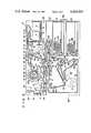
- FIG. 2is a side view schematically showing the internal arrangement of a bank note dispensing mechanism when the automatic bank note transaction apparatus in FIG. 1 is of the rear-operating type;
- FIG. 3is a front view showing an impeller and a temporary stacker
- FIG. 4is a side view showing a separation stopper
- FIG. 5is a side view schematically showing the internal arrangement of the bank note dispensing mechanism when the automatic bank note transaction apparatus in FIG. 1 is of the front-operating type;
- FIG. 6is a side view showing bank note dispensing passages when the apparatus used is of the rear-operating type.
- FIG. 7is a side view showing bank note dispensing passages when the apparatus used is of the front-operating type.
- reference numeral 1denotes a housing of an automatic deposit/withdrawal apparatus as the automatic bank note transaction apparatus.
- a customer operation part 2is disposed at the front of the housing 1.
- the customer operation part 2has a horizontal operation panel 2a disposed substantially half-way down the front side and a vertical operation panel 2b arising vertically from the rear edge of the horizontal operation panel 2a.
- a keyboard 3, a CRT display 4 for displaying information, and a port 5 which functions as both an insertion port and a dispensing portare arranged on the horizontal operation panel 2a.
- An ID card insertion port 6, a slip discharging port 7, a passbook insertion port 8, an envelope insertion port 9 and bank note dispensing port 10are arranged on the vertical operation panel 2b.
- a unit 11(not shown in detail) having a card reader which reads information from an ID card inserted through the ID card insertion port 6 and a slip issuing unit which conveys to the slip port 7 a slip on which transaction details are printed; a passbook reader/printer (not shown) which reads information from a magnetic strips on a passbook inserted through the passbook insertion port 8 and which records the transaction details on the passbook; an envelope processing unit (not shown) which prints predetermined characters on an envelope inserted through the envelope insertion port 9; a bank note deposit mechanism which transacts deposits of bank notes P inserted through the port 5; and a bank note dispensing mechanism 12 which dispenses at the bank note dispensing port 10 the bank notes P specified by a customer.
- the bank note dispensing mechanism 12has a first unit 12a and a second unit 12b which are vertically divided, as shown in FIGS. 2 and 5.
- the first unit 12a disposed under the second unit 12bhas first and second bank note dispensing compartments 13 and 14.
- the first unit 12acan be rotated through 180° with respect to the second unit 12b during installation.
- the bank note dispensing mechanism 12is detachably provided in the housing 1, while the first unit 12a is detachably mounted to the second unit 12b by means of a fixing mechanism (not shown).
- a front opening of the housing 1 for allowing mounting/dismounting of first and/or second bank note dispensing compartment 13 and/or 14 in the first unit 12a from the frontis formed at a portion of the front side of the housing 1 opposing one end face of the first unit 12a. This front opening is free to open and close through a front door 1a.
- a rear opening for allowing mounting/dismounting of the bank note dispensing mechanism 12 from the rearis formed at a portion of the rear side of the housing 1 opposing the other end face of the bank note dispensing mechanism 12. This rear opening is free to open and close through a rear door 1b.
- the first and second units 12a and 12bwill be described with reference to FIG. 2 wherein maintenance of the bank note dispensing compartments 13 and 14 is performed from the rear door 1b of the housing 1.
- the first unit 12ahas the first and second bank note dispensing compartments 13 and 14 which are vertically arranged therein at the rear side (right side in FIG. 2).
- First denomination notes Pae.g., 10-dollar notes or 1-pound notes
- Second denomination notes Pbe.g., 100-dollar notes or 10-pound notes
- Pickup mechanisms 15a and 15b and backup mechanisms 16a and 16bare mounted in the first and second bank note dispensing compartments 13 and 14, respectively.
- the pickup mechanisms 15a and 15btake out bank notes Pa and Pb, respectively, while the backup mechanisms 16a and 16b urge the bank notes Pa and Pb toward the pickup mechanisms 15a and 16b, respectively. Therefore, the first denomination note Pa or the second denomination note Pb is selectively taken out one by one through a first takeout port 13a or a second takeout port 13b.
- a door 12cis mounted on the rear end face (FIG. 2) of the first unit 12a so that the rear end face is free to open.
- a handle 12dis mounted substantially at the center of the door 12c.
- the first and second bank note dispensing compartments 13 and 14can be dismounted once the door 12c is opened.
- First conveying passages 17are located at the front part (left side in FIG. 2) of the first unit 12a to convey to the second unit 12b the first and/or second denomination note Pa and/or Pb which is selectively taken out from the first and second bank note dispensing compartments 13 and 14.
- the first conveying passages 17comprise a first denomination note conveying passage 17a which conveys the first denomination note Pa taken out of the first bank note dispensing compartment 13, a second denomination note conveying passage 17b which conveys the second denomination note Pb taken out of the second bank note dispensing compartment 14, and a common conveying passage 17c which continuously conveys the first denomination note Pa and/or the second denomination note Pb which is conveyed by the conveying passage 17a or 17b.
- the conveying passage 17ais disposed between the first takeout port 13a and an intermediate transferring station 18, and is defined between the opposing surfaces of a pair of first belts 21 and a pair of second belts 22 (one of the pair of first or second belts is only illustrated in FIG. 2).
- the pair of first belts 21is endlessly looped along the first takeout port 13a, the intermediate transferring station 18, a first transferring station 29 to be described later, and a second transferring station 30 to be described later.
- the pair of second belts 22is endlessly looped between the first takeout port 13a and the intermediate transferring station 18.
- a first counter 19a for counting the number of the first denomination notes Pa taken out of the first bank note dispensing compartment 13is arranged at the conveying passage 17a.
- the conveying passage 17bis formed between the second takeout port 13b and the intermediate transferring station 18 and is defined by the opposing surfaces of a pair of third belts 23 and a pair of fourth belts 24.
- the pair of third belts 23is endlessly looped along the second takeout port 13b, the intermediate station 18 and the first transferring station 29.
- the pair of fourth belts 24is endlessly looped along the second takeout port 13b and the intermediate transferring station 18.
- a second counter 19b for counting the number of second denomination notes Pb taken out of the second bank note dispensing compartment 14is arranged at the conveying passage 17b.
- the common conveying passage 17cis formed between the intermediate transferring station 18 and the second transferring station 30 through the first transferring station 29.
- the common conveying passage 17cis defined by the opposing surfaces of the pair of first belts 21 and the pair of third belts 23 and the opposing surfaces of the pair of first belts 21 and a pair of fifth belts 25.
- the pair of fifth belts 25is endlessly looped between the first transferring station 29 and the second transferring station 30.
- a note-overlap detector 19c and a discriminator 19d for discriminating between first and second denomination notes Pa and Pbare arranged at the common conveying passage 17c along the conveying direction in the order named.
- Each pair of belts 21, 22, 23, 24 and 25is driven by at least one drive roller 26.
- Each drive roller 26is driven by a motor 27 as the first driving source through a power transmission system 28, so that each pair of belts 21, 22, 23, 24 and 25 is driven in each predetermined direction.
- the first transferring station 29includes a first opening 29a formed on that portion of the upper part of the first unit 12a which is shifted by a predetermined distance d to the left (FIG. 2) from a central line (indicated by reference symbol l) of the first unit 12a; a movable roller 32 which is rotatably in contact with those portions of the lower surfaces of the pair of first belts 21 which are located below the first opening 29a; and a first guide plate 31 which obliquely crosses those portions of the pair of first belts 21 which are located below the first opening 29a. As shown in FIG.
- the movable roller 32is moved to a first position to urge those portions of the pair of first belts 21 upward which contact with the movable roller 32.
- the movable roller 32is brought into a second position so as not to urge those portions of the pair of first belts 21 upward.
- the first guide plate 31is moved to a third position to obliquely cross the pair of first belts 21.
- the first guide plate 31is brought into a fourth position so as not to cross the pair of first belts 21.
- a tension roller 36 as one of the rollers supporting the pair of first belts 21is brought into a fifth position (outward) by the tension of the pair of first belts 21 when the movable roller is kept in the first position, and that the tension roller 36 is brought into a sixth position (inward) to maintain predetermined tension of the pair of first belts 21 when the movable roller 32 is kept in the second position.
- the second transferring station 30includes a first opening 30a formed on that portion of the upper part of the first unit 12a which is shifted by the predetermined distance d to the right (FIG. 2) from the central line l, a stationary roller 30b which is rotatably in contact with those portions of the lower surfaces of part of the pair of first belts 21 which are located below the second opening 30a and are defined to oblique upward, and a second guide plate 34 which obliquely crosses those portions of the pair of first belts 21.
- the movable roller 32, the first guide plate 31 and the tension roller 36are respectively located in the first, third and fifth positions when the first and second bank note dispensing compartments 13 and 14 are located in the rear side as shown in FIG. 2.
- the first or second denomination notes Pa or Pb conveyed on the common conveying passage 17c of the conveying passages 17are taken out of the first unit 12a at the first transferring station 29 by the first guide plate 31 through the first opening 29a.
- the first and second bank note dispensing compartments 13 and 14are located in the front side, as shown in FIG.
- the movable roller 32, the first guide plate 31 and the tension roller 36are respectively located in the second, fourth and sixth positions.
- the first or second denomination notes Pa or Pb conveyed on the common conveying passage 17cpass through the first transferring station 29 and are taken out of the first unit 12a at the second transferring station 30 by the second guide plate 34 through the second opening 30a.
- the second unit 12bis arranged in the following manner.
- a bank note reception station 35is formed at that portion of the under part of the second unit 12b which is shifted by the predetermined distance d from the central line l.
- the bank note reception station 35has a third opening 35a at that portion of the bottom plate of the second unit 12b which is located immediately therebelow.
- the third opening 35a of the bank note reception station 35opposes the first opening 29a of the first transferring station 29. Therefore, the first and/or second denomination notes Pa and/or Pb taken out through the first opening 29a are received in the bank note reception station 35 of the second unit 12b through the third opening 35.
- the third opening 35aopposes the second opening 30a of the second transferring station 30. Therefore, the first and/or second denomination notes Pa and/or Pb taken out through the second opening 30a are received in the bank note reception station 35 through the third opening 35a.
- a conveying passage 37 for raising the first or second denomination notes Pa or Pb received in the bank note reception portion 35is formed substantially at the center of the second unit 12b.
- the conveying passage 37is formed between the bank note reception station 35 and a branch station 39 located thereabove.
- the conveying passage 37is defined by the opposing surfaces of a pair of sixth belts 43 and a pair of seventh belts 44.
- the pair of sixth belts 43is endlessly looped along the bank note reception station 35, the branch station 39, impellers 50 to be described later, and a temporary stacker 51.
- the pair of seventh belts 44is endlessly looped along the bank note reception station 35, the branch station 39 and a rejected bank note compartment 70.
- a first sorting gate 38is disposed at the branch station 39 of the conveying passage 37.
- the first sorting gate 38is operated by a gate actuator 42 which has a rotary solenoid.
- a bank note detector 19eis arranged at the middle of the conveying passage 37 to determine that the first or second denomination note Pa or Pb reaches thereat. Based on the detection results by the bank note detectors 19c and 19d, the gate actuator 42 causes the first sorting gate 38 to selectively transfer a proper bank note to a proper bank note conveying passage 40 and an rejected or recovered note to an rejected bank note conveying passage 41.
- the proper bank note conveying passage 40is disposed between the branch station 39 and the impellers 50 and is defined by the opposing surfaces of the pair of sixth belts 43 and a pair of eighth belts 45, and by the slant surfaces of the pair of sixth belts 43 adjacent to the opposing surfaces.
- the pair of eighth beltsis endlessly looped along the branch station 39 and an intermediate portion between the impellers 50 and the branch station 39.
- the rejected bank note conveying passage 41is defined between the branch station 39 and a rejected bank note compartment 70.
- This conveying passage 41is defined by the opposing surfaces of the pair of seventh conveyer belts 44 and a pair of ninth belts 46.
- the pair of ninth belts 46is endlessly looped along the branch station 39, the rejected bank note compartment 70 and a recovered bank note compartment 61.
- a recovered bank note conveying passage 66 which is adjacent to the rejected bank note conveying passage 41is defined between the rejected bank note compartment 70 and the recovered bank note compartment 61.
- the recovered bank note conveying passage 66is defined by the opposing surfaces of the pair of ninth belts 46 and a pair of tenth belts 67.
- the pair of tenth belts 67is endlessly looped between the rejected bank note compartment 70 and the recovered bank note compartment 61.
- a second sorting gate 69is disposed at the terminal end of the rejected bank note conveying passage 41.
- the second sorting gate 69is activated by a gate actuator 68 which has a solenoid. If a bank note which reaches the terminal end of the conveying passage 41 is a rejected one, the actuator 68 causes the second sorting gate 69 to cross the pair of ninth belts 46 and to store the rejected bank note in the rejected bank note compartment 70. However, if a recovered bank note reaches the terminal end of the conveying passage 41, the actuator 68 causes the second sorting gate 69 not to cross the pair of ninth belts 46 so that the bank note is transferred to the recovered bank note conveying passage 66 and is automatically stored in the recovered bank note compartment 61.
- Each pair of belts 43, 44, 45, 46 and 47is driven by at least one drive roller 47.
- Each drive roller 47is driven by a motor as a second driving source through the power transmission system 28 so that each pair of belts 43, 44, 45, 46 and 47 is driven in a predetermined direction, respectively.
- bank notes Pfails to reach the port 10 after a customer's account has been reduced by the equivalent amount. Further, suppose a customer leaves, by mistake, one of bank notes P fed to the port 10. In either case the bank note P is stored into the recovered bank note compartment 61. The recovered bank note does not belong to the bank, but to the customer. The bank temporarily keeps it for the customer. On the other hand, assume that one of the bank note P fails to reach the port 10 after a customer's account has been reduced by the equivalent amount. For example, when two overlapped bank notes P are taken out simultaneously the two overlapped bank notes P should not be handed to the customer as the rejected bank notes. Thus, this bank note as the rejected bank note belongs to the bank and must be stored in the rejected bank note compartment 70. The rejected bank note is then recirculated as a bank note.
- the pair of impellers 50is rotatably disposed at the terminal end of the proper bank note conveying passage 40 for proper bank notes, as shown in FIG. 3.
- the proper bank note conveyed by the conveying passage 40is held between a pair of adjacent blades among a plurality of blades 50a mounted on each impeller 50.
- the bank noteis conveyed to the temporary stacker 51.
- the bank note Pis then taken out of the impeller 50 by a pair of separation stoppers 52.
- the bank notes Pare stacked on a pair of conveyer belts 53 which define the bottom surface of the temporary stacker 51 and which are used to dispense/recover the bank notes.
- the impellers 50are mounted on a common rotating shaft 54. Rollers 55 are mounted at both ends of the rotating shaft 54.
- the sixth conveyer belts 43are mounted on the rollers 55, respectively.
- the separation stoppers 52are mounted on a driving shaft 56 which is rotated through a predetermined angle by a driving source (not shown).
- press rollers 57which are rotatably mounted at the distal ends of the separation stoppers 52 rotatably contact with those portions if the pair of sixth conveyer belts 43 which are mounted on the rollers 55, respectively, and the press rollers 57 cross the impellers 50. Therefore, the bank notes P conveyed to the temporary stacker 51 by the separation stoppers 52 are kept thereat.
- the separation stoppers 52are pivoted in the position as indicated by the alternate two dots and dash line in FIG. 4, so that the bank notes are held on the conveyer belts 53 through the press rollers 57.
- the separation stoppers 52act as press members for taking out the stacked bank notes P at one time.
- the pair of conveyer belts 53is endlessly looped between a roller 58 located near the bank note dispensing port 10 and a roller 59 located near the bank note reception station 35.
- a pinch roller 60is located on the upper surface portions of the conveyer belts 53 at the side of the bank note dispensing port 10.
- the pair of sixth belts 43respectively are in tight contact with those portions of the upper surfaces of the conveyer belts 53 which are located at the bank note reception station 35 side.
- the bank notes P stacked in the temporary stacker 51are compressed by the separation stoppers 52 and fed by the conveyer belts 53 either in the dispensing direction indicated by the broken arrow in FIG. 4 or in the recovery direction indicated by the solid arrow in FIG. 4.
- the bank notes Pare thus taken out at the bank note dispensing port 10 or are stored in the recovered bank note compartment 61.
- a bank note detector 62 for detecting the trailing ends of those bank notes P to be dispensed at the bank note dispensing port 10is arranged between the pinch roller 60 and the temporary stacker 51 to check whether or not the trailing ends of the bank notes P cross the detector 62.
- the detector 62detects the trailing ends of the bank notes P
- the running of the conveyer belts 53is stopped so that the bank notes P conveyed to the port 10 is not dropped from the conveyer belts 53.
- a shutter 64 selectively opened by a shutter actuator 63 of the plunger type magnet or the likeis arranged between the bank note dispensing port 10 and the pinch roller 60.
- a bank note detector 65is arranged behind the shutter 64.
- the bank notesare conveyed through the conveying passage 66 respectively to either the recovered bank note compartment 61 or the rejected bank note compartment 70 which are mounted at the rear portion of the second unit 12b.
- the conveying passage 66is constituted by the upper surfaces of the conveyer belts 53 and the conveying passages 37, 41 and 66.
- a counter 71is arranged at the middle of the conveying passage 40 and a counter 72 is arranged at the middle of the conveying passage 41.
- the counters 71 and 72count the number of proper bank notes and the number of rejected and recovered bank notes, respectively.
- a bank note detector 73is arranged at the terminal end of the conveying passage 66 to check whether the bank note to be recovered is properly conveyed into the recovered bank note compartment 61.
- the apparatusis installed between the customer hall and the staff office of the bank, the front side of the apparatus faces the customers and the apparatus is used as the rear-operating type as shown in FIG. 2.
- the first and second denomination notes Pa and Pbare selectively taken out of the first and second bank note dispensing compartments 13 and 14 through the pickup mechanisms 15a and 15b, respectively.
- the bank notes Pa and/or Pbthen pass through the common conveying passage 17c and are detected by the note-overlap detector 19c as to whether or not two overlapped bank notes are present.
- the bank notes Pa and/or Pbare further conveyed to the first transferring station 29 and then to the second unit 12b through the first opening 29a and the third opening 35a.
- the first and/or second denomination notes Pa and/or Pb sequentially conveyed in the second unit 12bare fed to the conveying passage 37 from the bank note reception station 35.
- the leading ends of the bank notesare detected by the bank note detector 19e, if the proper bank notes are detected, the first sorting gate 38 is pivoted counterclockwise (left side in FIG. 2) and they are conveyed along the conveying passage 40.
- the bank notes Pa and/or Pbare then conveyed to the temporary stacker 51 through the impellers 50 and leave the impellers 50 when the end faces of the bank notes Pa and/or Pb abut against the separation stoppers 52.
- the bank notes Pa and/or Pbdrop onto the temporary stacker 51 and are then stacked on the conveyer belts 53.
- the lower ends 52a of the separation stoppers 52are fitted around the upper and side surfaces of the conveyer belts 53, trailing ends of the bank notes are well-aligned.
- the bank notes P corresponding to a predetermined amountare taken out of the first and second bank note dispensing compartments 13 and 14. Any two overlapped bank notes are eliminated. Further, if the count of the counter 71 corresponds to the predetermined amount, the conveyer belts 53 are temporarily stopped and the impellers 50 are also stopped in response to the interruption of travel of the conveyer belts 53.
- the temporarily stacked bank notes in the temporary stacker 51are pressed onto the belts 53.
- the conveyer belts 53start travelling in the dispensing direction.
- the bank notes P stacked in the temporary stacker 51are collectively conveyed to the bank note dispensing port 10.
- the shutter 64is opened by the shutter actuator 63.
- the conveying operationis interrupted.
- the leading ends of the bank notes Pextend through the bank note dispensing port 10, while the trailing ends thereof are clamped between the conveyer belts 53 and the pinch roller 60.
- the thick solid lines in FIG. 6indicate the conveying route of the proper bank notes.
- the first sorting gate 38is pivoted clockwise as shown in FIG. 7 and the bank notes are conveyed on the conveying passage 41.
- the rejected bank notesare then stored in the rejected bank note compartment 70 through the second sorting gate 69. If this occurs, first and/or second bank notes Pa and/or Pb corresponding to the short fall against the amount specified by the customer are taken out of the first bank note dispensing compartment 13 and/or the second bank note dispensing compartment 14.
- bank notes which correspond to the specified amount of moneyare stacked in the temporary stacker 51.
- the thick broken lines in FIG. 6indicate the conveying route of the rejected bank notes.
- a timer(not shown) generates a signal to maintain the separation stoppers 52 in the position indicated by the solid line.
- the motor 48is then driven in the reverse direction to drive the conveyer belts 53 in the recovery direction as indicated by the solid arrow in FIG. 4.
- the dispensed bank notesare fed back from the bank note dispensing port 10 as recovered bank notes.
- the shutter 64is closed.
- the recovered bank notes fed back into the temporary stacker 51come in contact with the separation stoppers 52 so that the leading ends thereof are well-aligned.
- the separation stoppers 52are pivoted to a position indicated by the one dot and dash line.
- the press rollers 57 mounted at the distal ends of the separation stoppersrespectively urge the bank notes toward the conveyer belts 53.
- the lower ends 52a of the separation stoppers 52 which are fitted around the upper and side surfaces of the conveyer belts 53respectively are released so that the bank notes P stacked in the temporary stacker 51 are collectively conveyed into the conveying passage 41.
- the second sorting gate 69Since the second sorting gate 69 is kept in the open position by the detection signal from the counter 72, the bank notes pass through the conveying passage 66 and are recovered into the recovered bank note compartment 61.
- the thick one dot and dash lineindicates the conveying route of the bank notes to be recovered, as shown in FIGS. 6 and 7.
- the bank notes to be stored in the rejected bank note compartment 70are erroneously stacked in the temporary stacker 51, they can be recovered in the same manner as the recovered bank notes. However, in this case, the second sorting gate 69 is closed, so that the bank notes are not conveyed into the conveying passage 66 but into the conveying passage 41. Thereafter, the rejected bank notes are stored in the rejected bank note compartment 70.
- the bank note dispensing operationis performed as described above, and the number of bank notes Pa and Pb decreases.
- the first and second bank note dispensing compartments 13 and 14are filled during routine maintenance with bank notes Pa and Pb respectively from the back, that is, from the inside of the staff office.
- the operatoropens the rear door 1b to open the rear portion of the housing 1 and also opens the door 12c.
- the first unit 12ais disclosed to the staff office.
- routine maintenance for the first and second bank note dispensing compartments 13 and 14is performed only from the inside of the staff office.
- the automatic deposit/withdrawal apparatusis installed against a wall, routine maintenance cannot be performed from the rear side; the bank notes can be filled into the apparatus only from the front side.
- the operatoropens the rear door 1b and draws the bank note dispensing mechanism 12 out of the housing 1.
- the first unit 12ais turned by 180° with respect to the second unit 12b, thereby taking such a position as shown in FIG. 5.
- the bank note dispensing mechanism 12is set in the housing 1.
- the first and second bank note compartments 13 and 14are located at the front side of the housing 1, as shown in FIG. 5. This arrangement allows routine maintenance for the compartments 13 and 14 from the front side.
- the bank note reception station 35 of the second unit 12bopposes the second transferring station 30 of the first unit 12a.
- the movable roller 32 of the first transferring station 29a, the first guide plate 31 and the tension roller 36are kept in the second, fourth and sixth positions, respectively. Therefore, when the apparatus is used as the front-operating type, the first and/or second denomination notes Pa and/or Pb taken out of the first and/or second bank note dispensing compartment 13 and/or 14 are conveyed into the second unit 12b from the second transferring station 30 through the second opening 30 a and the third opening 35a.
- the conveying operation within the second unit 12bis the same as that of the apparatus when it is used as the rear-operating type.
- the most suitable operating modethat is, a front-operation mode or a rear-operation mode
- the bankcan install and deploy the apparatus in any location, resulting in low cost and convenience.
- an automatic deposit/withdrawal apparatuseliminates this problem. If a customer orders an apparatus of the front-operating type, the manufacturer merely changes the mounting position of the bank note dispensing compartments. Therefore, speculative production is possible and productivity is thus greatly increased.
Landscapes
- Business, Economics & Management (AREA)
- Accounting & Taxation (AREA)
- Finance (AREA)
- Physics & Mathematics (AREA)
- General Physics & Mathematics (AREA)
- Financial Or Insurance-Related Operations Such As Payment And Settlement (AREA)
- Pile Receivers (AREA)
Abstract
Description
Claims (5)
Applications Claiming Priority (2)
| Application Number | Priority Date | Filing Date | Title |
|---|---|---|---|
| JP56107683AJPS5810265A (en) | 1981-07-10 | 1981-07-10 | Currency automatic transaction device |
| JP56-107683 | 1981-07-10 |
Publications (1)
| Publication Number | Publication Date |
|---|---|
| US4434359Atrue US4434359A (en) | 1984-02-28 |
Family
ID=14465315
Family Applications (1)
| Application Number | Title | Priority Date | Filing Date |
|---|---|---|---|
| US06/395,311Expired - Fee RelatedUS4434359A (en) | 1981-07-10 | 1982-07-06 | Automatic bank note transaction apparatus |
Country Status (3)
| Country | Link |
|---|---|
| US (1) | US4434359A (en) |
| JP (1) | JPS5810265A (en) |
| GB (1) | GB2106687B (en) |
Cited By (99)
| Publication number | Priority date | Publication date | Assignee | Title |
|---|---|---|---|---|
| USD279479S (en) | 1982-07-09 | 1985-07-02 | De La Rue Systems Limited | Banknote sorter |
| USD282114S (en) | 1983-03-30 | 1986-01-07 | Tokyo Shibaura Denki Kabushiki Kaisha | Automatic teller machine |
| USD282937S (en) | 1983-05-23 | 1986-03-11 | Fujitsu Limited | Cash dispenser |
| USD282936S (en) | 1983-04-28 | 1986-03-11 | Atlantic Richfield Company | Vending machine currency acceptor |
| US4578009A (en)* | 1984-03-28 | 1986-03-25 | Ncr Corporation | Collector and carriage mechanism for use in a sheet dispenser |
| US4602332A (en)* | 1983-01-26 | 1986-07-22 | Tokyo Shibaura Denki Kabushiki Kaisha | Automatic bank note transaction apparatus |
| US4630200A (en)* | 1983-03-01 | 1986-12-16 | Omron Tateisi Electronics Co. | Electronic cash register capable of performing cash-dispensing transactions |
| USD289216S (en) | 1984-02-28 | 1987-04-07 | Kabushiki Kaisha Toshiba | Automatic teller machine |
| US4709820A (en)* | 1984-03-12 | 1987-12-01 | De La Rue Systems Limited | Sheet dispensing apparatus |
| US4747493A (en)* | 1984-09-03 | 1988-05-31 | Omron Tateisi Electronics Co., Ltd. | Cash dispenser |
| US4772005A (en)* | 1984-02-20 | 1988-09-20 | De La Rue Systems Limited | Sheet feeding apparatus |
| US4782225A (en)* | 1986-03-25 | 1988-11-01 | Kabushiki Kaisha Toshiba | Sheet-processing apparatus including optical sensor cleaning device |
| USD299133S (en) | 1987-05-08 | 1988-12-27 | Protel, Inc. | Key pad and credit card bezel for coin telephones |
| USD299341S (en) | 1987-05-08 | 1989-01-10 | Protel, Inc. | Housing for a key pad, carrier select and credit card bezel for coin telephones |
| US4863038A (en)* | 1986-10-30 | 1989-09-05 | Laurel Bank Machines Co., Ltd. | Bill receiving and dispensing machine |
| US4941656A (en)* | 1986-12-08 | 1990-07-17 | Unisys Corp. | Sheet handling mechanism |
| US4980543A (en)* | 1983-01-26 | 1990-12-25 | Tokyo Shibaura Denki Kabushiki Kaisha | Multiple denominator bank note depositor/dispenser with automatic loading to and from storage section |
| USD317071S (en) | 1988-05-11 | 1991-05-21 | Ncr Corporation | Self service terminal or similar article |
| USD327766S (en) | 1989-12-01 | 1992-07-07 | Ncr Corporation | Self service terminal |
| US5240368A (en)* | 1989-12-04 | 1993-08-31 | Diebold, Inc. | Sheet handling apparatus |
| US5564546A (en)* | 1992-09-04 | 1996-10-15 | Coinstar, Inc. | Coin counter/sorter and coupon/voucher dispensing machine and method |
| USD377170S (en)* | 1995-04-24 | 1997-01-07 | King Products Inc. | Public interactive kiosk |
| US5597996A (en)* | 1995-11-16 | 1997-01-28 | Ncr Corporation | Cash dispensing apparatus (ATM) and method for separating rejected bank notes |
| US5620079A (en)* | 1992-09-04 | 1997-04-15 | Coinstar, Inc. | Coin counter/sorter and coupon/voucher dispensing machine and method |
| US5746299A (en)* | 1995-04-27 | 1998-05-05 | Coinstar, Inc. | Coin counter dejamming method and apparatus |
| WO1998059308A1 (en)* | 1997-05-30 | 1998-12-30 | Capital Security Systems, Inc. | An automated document cashing system |
| US5897625A (en)* | 1997-05-30 | 1999-04-27 | Capital Security Systems, Inc. | Automated document cashing system |
| US5909794A (en)* | 1992-09-04 | 1999-06-08 | Coinstar, Inc. | Donation transaction method and apparatus |
| US5987439A (en)* | 1997-05-30 | 1999-11-16 | Capital Security Systems, Inc. | Automated banking system for making change on a card or user account |
| US5988348A (en)* | 1996-06-28 | 1999-11-23 | Coinstar, Inc. | Coin discrimination apparatus and method |
| US6012048A (en)* | 1997-05-30 | 2000-01-04 | Capital Security Systems, Inc. | Automated banking system for dispensing money orders, wire transfer and bill payment |
| US6123327A (en)* | 1996-03-13 | 2000-09-26 | Siemens Nixdorf Informationssysteme Aktiengesellschaft | Cash dispenser |
| US6318537B1 (en) | 1999-04-28 | 2001-11-20 | Cummins-Allison Corp. | Currency processing machine with multiple internal coin receptacles |
| US20020020603A1 (en)* | 2000-02-11 | 2002-02-21 | Jones, William, J. | System and method for processing currency bills and substitute currency media in a single device |
| US6357657B1 (en)* | 1999-06-29 | 2002-03-19 | Ncr Corporation | Anti-fraud device |
| US20020126885A1 (en)* | 1996-05-13 | 2002-09-12 | Mennie Douglas U. | Automatic funds processing system |
| US6494776B1 (en) | 1992-09-04 | 2002-12-17 | Coinstar, Inc. | Coin counter/sorter and coupon/voucher dispensing machine and method |
| US6536664B2 (en) | 1995-05-30 | 2003-03-25 | Cashguard Ab | Method for exchanging information between a cash register and a payment-processing device |
| US20030057054A1 (en)* | 2001-09-21 | 2003-03-27 | Waechter Mark L. | Method and apparatus for coin or object sensing using adaptive operating point control |
| US6602125B2 (en) | 2001-05-04 | 2003-08-05 | Coinstar, Inc. | Automatic coin input tray for a self-service coin-counting machine |
| US6637576B1 (en) | 1999-04-28 | 2003-10-28 | Cummins-Allison Corp. | Currency processing machine with multiple internal coin receptacles |
| US20040016797A1 (en)* | 2002-07-23 | 2004-01-29 | Jones William J. | System and method for processing currency bills and documents bearing barcodes in a document processing device |
| EP1209633A3 (en)* | 2000-11-24 | 2004-03-10 | Hitachi, Ltd. | Bill handling machine |
| US6736251B2 (en) | 1992-09-04 | 2004-05-18 | Coinstar, Inc. | Coin counter and voucher dispensing machine and method |
| US6766892B2 (en) | 1996-06-28 | 2004-07-27 | Coinstar, Inc. | Coin discrimination apparatus and method |
| US20040154964A1 (en)* | 2003-02-07 | 2004-08-12 | Jones John E. | Currency dispenser |
| US6778693B2 (en) | 1995-05-02 | 2004-08-17 | Cummins-Allison Corp. | Automatic currency processing system having ticket redemption module |
| WO2004081888A1 (en)* | 2003-03-11 | 2004-09-23 | Cima S.P.A. Di Razzaboni & C. | Machine for the orderly storage and delivery of banknotes |
| US6798899B2 (en) | 2001-01-04 | 2004-09-28 | Cummins-Allison Corp. | Document feeding method and apparatus |
| US20050035193A1 (en)* | 1997-05-30 | 2005-02-17 | Capital Security Systems, Inc. | Automated document cashing system |
| KR100471934B1 (en)* | 2001-01-19 | 2005-03-08 | 가부시키가이샤 히타치세이사쿠쇼 | Handling device for paper |
| US6983879B2 (en)* | 2002-11-26 | 2006-01-10 | Diebold Self-Service Systems Division Of Diebold, Incorporated | Cash dispensing automated banking machine with improved resistance to fraud |
| US20060012113A1 (en)* | 2004-07-16 | 2006-01-19 | Lg N-Sys Inc. | Media dispenser |
| US20060037835A1 (en)* | 2002-02-15 | 2006-02-23 | Michael Doran | Methods and systems for exchanging and or transferring various forms of value |
| US20060064379A1 (en)* | 2002-02-15 | 2006-03-23 | Michael Doran | Methods and systems for exchanging and/or transferring various forms of valve |
| US20060069642A1 (en)* | 2002-02-15 | 2006-03-30 | Michael Doran | Methods and systems for exchanging and or transferring various forms of value |
| US7028827B1 (en) | 1992-09-04 | 2006-04-18 | Coinstar, Inc. | Coin counter/sorter and coupon/voucher dispensing machine and method |
| US20060175176A1 (en)* | 2005-02-10 | 2006-08-10 | Blake John R | Method and apparatus for varying coin-processing machine receptacle limits |
| US20060191770A1 (en)* | 1996-03-07 | 2006-08-31 | Dan Gerrity | Method and apparatus for conditioning coins prior to discrimination |
| US20060207856A1 (en)* | 2002-02-15 | 2006-09-21 | Dean Scott A | Methods and systems for exchanging and/or transferring various forms of value |
| US20060244193A1 (en)* | 2005-04-27 | 2006-11-02 | Lee Won J | Apparatus of withdrawing cash from cash transaction machine |
| US20070119681A1 (en)* | 2005-11-12 | 2007-05-31 | Blake John R | Coin processing device having a moveable coin receptacle station |
| US7349566B2 (en) | 1997-04-14 | 2008-03-25 | Cummins-Allison Corp. | Image processing network |
| US7445145B1 (en)* | 2004-07-29 | 2008-11-04 | Diebold Self-Service Systems Division Of Diebold, Incorporated | Cash dispensing automated banking machine deposit printing system and method |
| US20090239459A1 (en)* | 2008-03-19 | 2009-09-24 | Cummins-Allison Corp. | Self Service Coin Processing Machines With EPOS Terminal And Method For Automated Payout Utilizing Same |
| US20090236201A1 (en)* | 1996-05-13 | 2009-09-24 | Blake John R | Apparatus, System and Method For Coin Exchange |
| US20090320106A1 (en)* | 2006-03-23 | 2009-12-24 | Cummins-Allison Corportation | Systems, apparatus, and methods for currency processing control and redemption |
| US7929749B1 (en) | 2006-09-25 | 2011-04-19 | Cummins-Allison Corp. | System and method for saving statistical data of currency bills in a currency processing device |
| US8042732B2 (en) | 2008-03-25 | 2011-10-25 | Cummins-Allison Corp. | Self service coin redemption card printer-dispenser |
| US8393455B2 (en) | 2003-03-12 | 2013-03-12 | Cummins-Allison Corp. | Coin processing device having a moveable coin receptacle station |
| US20130099439A1 (en)* | 2010-06-23 | 2013-04-25 | Wincor Nixdorf International Gmbh | Device for disbursing value notes comprising a stationary support element |
| USRE44252E1 (en) | 2002-01-10 | 2013-06-04 | Cummins-Allison Corp. | Coin redemption system |
| US8523641B2 (en) | 2004-09-15 | 2013-09-03 | Cummins-Allison Corp. | System, method and apparatus for automatically filling a coin cassette |
| US8545295B2 (en) | 2010-12-17 | 2013-10-01 | Cummins-Allison Corp. | Coin processing systems, methods and devices |
| US8559694B2 (en) | 2005-10-05 | 2013-10-15 | Cummins-Allison Corp. | Currency processing system with fitness detection |
| USRE44689E1 (en) | 2002-03-11 | 2014-01-07 | Cummins-Allison Corp. | Optical coin discrimination sensor and coin processing system using the same |
| US8684160B2 (en) | 2000-04-28 | 2014-04-01 | Cummins-Allison Corp. | System and method for processing coins |
| US8874467B2 (en) | 2011-11-23 | 2014-10-28 | Outerwall Inc | Mobile commerce platforms and associated systems and methods for converting consumer coins, cash, and/or other forms of value for use with same |
| US8967361B2 (en) | 2013-02-27 | 2015-03-03 | Outerwall Inc. | Coin counting and sorting machines |
| US9022841B2 (en) | 2013-05-08 | 2015-05-05 | Outerwall Inc. | Coin counting and/or sorting machines and associated systems and methods |
| US9036890B2 (en) | 2012-06-05 | 2015-05-19 | Outerwall Inc. | Optical coin discrimination systems and methods for use with consumer-operated kiosks and the like |
| US9064268B2 (en) | 2010-11-01 | 2015-06-23 | Outerwall Inc. | Gift card exchange kiosks and associated methods of use |
| US9092924B1 (en) | 2012-08-31 | 2015-07-28 | Cummins-Allison Corp. | Disk-type coin processing unit with angled sorting head |
| US9129294B2 (en) | 2012-02-06 | 2015-09-08 | Outerwall Inc. | Coin counting machines having coupon capabilities, loyalty program capabilities, advertising capabilities, and the like |
| US9235945B2 (en) | 2014-02-10 | 2016-01-12 | Outerwall Inc. | Coin input apparatuses and associated methods and systems |
| US9430893B1 (en) | 2014-08-06 | 2016-08-30 | Cummins-Allison Corp. | Systems, methods and devices for managing rejected coins during coin processing |
| US9443367B2 (en) | 2014-01-17 | 2016-09-13 | Outerwall Inc. | Digital image coin discrimination for use with consumer-operated kiosks and the like |
| US9501885B1 (en) | 2014-07-09 | 2016-11-22 | Cummins-Allison Corp. | Systems, methods and devices for processing coins utilizing near-normal and high-angle of incidence lighting |
| US9508208B1 (en) | 2014-07-25 | 2016-11-29 | Cummins Allison Corp. | Systems, methods and devices for processing coins with linear array of coin imaging sensors |
| US9818249B1 (en) | 2002-09-04 | 2017-11-14 | Copilot Ventures Fund Iii Llc | Authentication method and system |
| US9875593B1 (en) | 2015-08-07 | 2018-01-23 | Cummins-Allison Corp. | Systems, methods and devices for coin processing and coin recycling |
| US9916713B1 (en) | 2014-07-09 | 2018-03-13 | Cummins-Allison Corp. | Systems, methods and devices for processing coins utilizing normal or near-normal and/or high-angle of incidence lighting |
| US9934640B2 (en) | 2004-09-15 | 2018-04-03 | Cummins-Allison Corp. | System, method and apparatus for repurposing currency |
| US10089812B1 (en) | 2014-11-11 | 2018-10-02 | Cummins-Allison Corp. | Systems, methods and devices for processing coins utilizing a multi-material coin sorting disk |
| US10181234B2 (en) | 2016-10-18 | 2019-01-15 | Cummins-Allison Corp. | Coin sorting head and coin processing system using the same |
| US10346819B2 (en) | 2015-11-19 | 2019-07-09 | Coinstar Asset Holdings, Llc | Mobile device applications, other applications and associated kiosk-based systems and methods for facilitating coin saving |
| US10679449B2 (en) | 2016-10-18 | 2020-06-09 | Cummins-Allison Corp. | Coin sorting head and coin processing system using the same |
| US10685523B1 (en) | 2014-07-09 | 2020-06-16 | Cummins-Allison Corp. | Systems, methods and devices for processing batches of coins utilizing coin imaging sensor assemblies |
| US11443581B2 (en) | 2019-01-04 | 2022-09-13 | Cummins-Allison Corp. | Coin pad for coin processing system |
Families Citing this family (8)
| Publication number | Priority date | Publication date | Assignee | Title |
|---|---|---|---|---|
| JPH01120692A (en)* | 1987-11-04 | 1989-05-12 | Fujitsu Ltd | Automatic cash defraying machine |
| GB8825756D0 (en)* | 1988-11-03 | 1988-12-07 | Ncr Co | Sheet handling apparatus |
| JP2685254B2 (en)* | 1988-11-30 | 1997-12-03 | 株式会社東芝 | Automatic transaction equipment |
| GB9812837D0 (en) | 1998-06-16 | 1998-08-12 | Ncr Int Inc | Sheet dispensing mechanism |
| GB9812839D0 (en) | 1998-06-16 | 1998-08-12 | Ncr Int Inc | Sheet dispensing mechanism |
| GB9812841D0 (en) | 1998-06-16 | 1998-08-12 | Ncr Int Inc | Sheet dispensing mechanism |
| DE102016105166A1 (en) | 2016-03-21 | 2017-09-21 | Keba Ag | ATM |
| DE102017129492A1 (en) | 2017-12-11 | 2019-06-13 | Keba Ag | ATM |
Citations (3)
| Publication number | Priority date | Publication date | Assignee | Title |
|---|---|---|---|---|
| US3697729A (en) | 1969-09-09 | 1972-10-10 | John David Edwards | Dispensing system and security card for use therewith |
| US4282424A (en) | 1979-03-28 | 1981-08-04 | Tokyo Shibaura Denki Kabushiki Kaisha | Automatic cash dispensing machine |
| US4369360A (en) | 1980-04-15 | 1983-01-18 | Laurel Bank Machine Co., Ltd. | Bank note depositing apparatus |
Family Cites Families (2)
| Publication number | Priority date | Publication date | Assignee | Title |
|---|---|---|---|---|
| JPS5586242U (en)* | 1978-12-06 | 1980-06-14 | ||
| JPS5597683A (en)* | 1979-01-17 | 1980-07-25 | Omron Tateisi Electronics Co | Both faces use type bill dispenser |
- 1981
- 1981-07-10JPJP56107683Apatent/JPS5810265A/enactiveGranted
- 1982
- 1982-07-05GBGB08219347Apatent/GB2106687B/ennot_activeExpired
- 1982-07-06USUS06/395,311patent/US4434359A/ennot_activeExpired - Fee Related
Patent Citations (3)
| Publication number | Priority date | Publication date | Assignee | Title |
|---|---|---|---|---|
| US3697729A (en) | 1969-09-09 | 1972-10-10 | John David Edwards | Dispensing system and security card for use therewith |
| US4282424A (en) | 1979-03-28 | 1981-08-04 | Tokyo Shibaura Denki Kabushiki Kaisha | Automatic cash dispensing machine |
| US4369360A (en) | 1980-04-15 | 1983-01-18 | Laurel Bank Machine Co., Ltd. | Bank note depositing apparatus |
Cited By (189)
| Publication number | Priority date | Publication date | Assignee | Title |
|---|---|---|---|---|
| USD279479S (en) | 1982-07-09 | 1985-07-02 | De La Rue Systems Limited | Banknote sorter |
| US4602332A (en)* | 1983-01-26 | 1986-07-22 | Tokyo Shibaura Denki Kabushiki Kaisha | Automatic bank note transaction apparatus |
| US4980543A (en)* | 1983-01-26 | 1990-12-25 | Tokyo Shibaura Denki Kabushiki Kaisha | Multiple denominator bank note depositor/dispenser with automatic loading to and from storage section |
| US4630200A (en)* | 1983-03-01 | 1986-12-16 | Omron Tateisi Electronics Co. | Electronic cash register capable of performing cash-dispensing transactions |
| USD282114S (en) | 1983-03-30 | 1986-01-07 | Tokyo Shibaura Denki Kabushiki Kaisha | Automatic teller machine |
| USD282936S (en) | 1983-04-28 | 1986-03-11 | Atlantic Richfield Company | Vending machine currency acceptor |
| USD282937S (en) | 1983-05-23 | 1986-03-11 | Fujitsu Limited | Cash dispenser |
| US4772005A (en)* | 1984-02-20 | 1988-09-20 | De La Rue Systems Limited | Sheet feeding apparatus |
| USD289216S (en) | 1984-02-28 | 1987-04-07 | Kabushiki Kaisha Toshiba | Automatic teller machine |
| US4709820A (en)* | 1984-03-12 | 1987-12-01 | De La Rue Systems Limited | Sheet dispensing apparatus |
| US4578009A (en)* | 1984-03-28 | 1986-03-25 | Ncr Corporation | Collector and carriage mechanism for use in a sheet dispenser |
| US4747493A (en)* | 1984-09-03 | 1988-05-31 | Omron Tateisi Electronics Co., Ltd. | Cash dispenser |
| US4782225A (en)* | 1986-03-25 | 1988-11-01 | Kabushiki Kaisha Toshiba | Sheet-processing apparatus including optical sensor cleaning device |
| US4863038A (en)* | 1986-10-30 | 1989-09-05 | Laurel Bank Machines Co., Ltd. | Bill receiving and dispensing machine |
| US4941656A (en)* | 1986-12-08 | 1990-07-17 | Unisys Corp. | Sheet handling mechanism |
| USD299133S (en) | 1987-05-08 | 1988-12-27 | Protel, Inc. | Key pad and credit card bezel for coin telephones |
| USD299341S (en) | 1987-05-08 | 1989-01-10 | Protel, Inc. | Housing for a key pad, carrier select and credit card bezel for coin telephones |
| USD317071S (en) | 1988-05-11 | 1991-05-21 | Ncr Corporation | Self service terminal or similar article |
| USD327766S (en) | 1989-12-01 | 1992-07-07 | Ncr Corporation | Self service terminal |
| US5342165A (en)* | 1989-12-04 | 1994-08-30 | Diebold, Incorporated | Sheet handling apparatus |
| US5240368A (en)* | 1989-12-04 | 1993-08-31 | Diebold, Inc. | Sheet handling apparatus |
| US7028827B1 (en) | 1992-09-04 | 2006-04-18 | Coinstar, Inc. | Coin counter/sorter and coupon/voucher dispensing machine and method |
| US20060060445A1 (en)* | 1992-09-04 | 2006-03-23 | Molbak Jens H | Coin counter and voucher dispensing machine and method |
| US20080087520A1 (en)* | 1992-09-04 | 2008-04-17 | Coinstar, Inc. | Coin counter and voucher dispensing machine and method |
| US5620079A (en)* | 1992-09-04 | 1997-04-15 | Coinstar, Inc. | Coin counter/sorter and coupon/voucher dispensing machine and method |
| US7303119B2 (en) | 1992-09-04 | 2007-12-04 | Coinstar, Inc. | Coin counter and voucher dispensing machine and method |
| US5799767A (en)* | 1992-09-04 | 1998-09-01 | Coinstar, Inc. | Cleaning apparatus and method for a coin counter and voucher dispenser |
| US20070069007A1 (en)* | 1992-09-04 | 2007-03-29 | Molbak Jens H | Coin counter and voucher dispensing machine and method |
| US7131580B2 (en) | 1992-09-04 | 2006-11-07 | Coinstar, Inc. | Coin counter and voucher dispensing machine and method |
| US5909794A (en)* | 1992-09-04 | 1999-06-08 | Coinstar, Inc. | Donation transaction method and apparatus |
| US6494776B1 (en) | 1992-09-04 | 2002-12-17 | Coinstar, Inc. | Coin counter/sorter and coupon/voucher dispensing machine and method |
| US7527193B2 (en) | 1992-09-04 | 2009-05-05 | Coinstar, Inc. | Coin counter and voucher dispensing machine and method |
| US7971699B2 (en) | 1992-09-04 | 2011-07-05 | Coinstar, Inc. | Coin counter/sorter and coupon/voucher dispensing machine and method |
| US7874478B2 (en) | 1992-09-04 | 2011-01-25 | Coinstar, Inc. | Coin counter and voucher dispensing machine and method |
| US6047807A (en)* | 1992-09-04 | 2000-04-11 | Coinstar, Inc. | Restricted access coin counter |
| US6976570B2 (en) | 1992-09-04 | 2005-12-20 | Coinstar, Inc. | Coin counter and voucher dispensing machine and method |
| US6854581B2 (en) | 1992-09-04 | 2005-02-15 | Coinstar, Inc. | Coin counter and voucher dispensing machine and method |
| US6758316B2 (en) | 1992-09-04 | 2004-07-06 | Coinstar, Inc. | Coin counter and voucher dispensing machine and method |
| US20040124062A1 (en)* | 1992-09-04 | 2004-07-01 | Molbak Jens H. | Coin counter and voucher dispensing machine and method |
| US6736251B2 (en) | 1992-09-04 | 2004-05-18 | Coinstar, Inc. | Coin counter and voucher dispensing machine and method |
| US5564546A (en)* | 1992-09-04 | 1996-10-15 | Coinstar, Inc. | Coin counter/sorter and coupon/voucher dispensing machine and method |
| US6484863B1 (en) | 1994-05-03 | 2002-11-26 | Coinstar Inc. | Coin counter/sorter and coupon/voucher dispensing machine and method |
| USD377170S (en)* | 1995-04-24 | 1997-01-07 | King Products Inc. | Public interactive kiosk |
| US5746299A (en)* | 1995-04-27 | 1998-05-05 | Coinstar, Inc. | Coin counter dejamming method and apparatus |
| US6095313A (en)* | 1995-04-27 | 2000-08-01 | Coinstar, Inc. | Coin counter dejamming method and apparatus |
| US5957262A (en)* | 1995-04-27 | 1999-09-28 | Coinstar, Inc. | Coin counter dejamming method and apparatus |
| US20070071302A1 (en)* | 1995-05-02 | 2007-03-29 | Jones William J | Automatic currency processing system |
| US7778456B2 (en) | 1995-05-02 | 2010-08-17 | Cummins-Allison, Corp. | Automatic currency processing system having ticket redemption module |
| US20030081824A1 (en)* | 1995-05-02 | 2003-05-01 | Mennie Douglas U. | Automatic currency processing system |
| US6778693B2 (en) | 1995-05-02 | 2004-08-17 | Cummins-Allison Corp. | Automatic currency processing system having ticket redemption module |
| US8023715B2 (en) | 1995-05-02 | 2011-09-20 | Cummins-Allison Corporation | Automatic currency processing system having ticket redemption module |
| US6536664B2 (en) | 1995-05-30 | 2003-03-25 | Cashguard Ab | Method for exchanging information between a cash register and a payment-processing device |
| US5597996A (en)* | 1995-11-16 | 1997-01-28 | Ncr Corporation | Cash dispensing apparatus (ATM) and method for separating rejected bank notes |
| US7464802B2 (en) | 1996-03-07 | 2008-12-16 | Coinstar, Inc. | Method and apparatus for conditioning coins prior to discrimination |
| US20060191770A1 (en)* | 1996-03-07 | 2006-08-31 | Dan Gerrity | Method and apparatus for conditioning coins prior to discrimination |
| US20090159395A1 (en)* | 1996-03-07 | 2009-06-25 | Dan Gerrity | Method and apparatus for conditioning coins prior to discrimination |
| US6123327A (en)* | 1996-03-13 | 2000-09-26 | Siemens Nixdorf Informationssysteme Aktiengesellschaft | Cash dispenser |
| US20110099105A1 (en)* | 1996-05-13 | 2011-04-28 | Cummins-Allison Corp. | Self-service currency exchange machine |
| US20020126885A1 (en)* | 1996-05-13 | 2002-09-12 | Mennie Douglas U. | Automatic funds processing system |
| US8950566B2 (en) | 1996-05-13 | 2015-02-10 | Cummins Allison Corp. | Apparatus, system and method for coin exchange |
| US8229821B2 (en) | 1996-05-13 | 2012-07-24 | Cummins-Allison Corp. | Self-service currency exchange machine |
| US20090236201A1 (en)* | 1996-05-13 | 2009-09-24 | Blake John R | Apparatus, System and Method For Coin Exchange |
| US8346610B2 (en) | 1996-05-13 | 2013-01-01 | Cummins-Allison Corp. | Automated document processing system using full image scanning |
| US8352322B2 (en) | 1996-05-13 | 2013-01-08 | Cummins-Allison Corp. | Automated document processing system using full image scanning |
| US20070221470A1 (en)* | 1996-05-13 | 2007-09-27 | Mennie Douglas U | Automated document processing system using full image scanning |
| US8443958B2 (en) | 1996-05-13 | 2013-05-21 | Cummins-Allison Corp. | Apparatus, system and method for coin exchange |
| US7949582B2 (en) | 1996-05-13 | 2011-05-24 | Cummins-Allison Corp. | Machine and method for redeeming currency to dispense a value card |
| US7213697B2 (en) | 1996-06-28 | 2007-05-08 | Coinstar, Inc. | Coin discrimination apparatus and method |
| US6766892B2 (en) | 1996-06-28 | 2004-07-27 | Coinstar, Inc. | Coin discrimination apparatus and method |
| US20090166151A1 (en)* | 1996-06-28 | 2009-07-02 | Douglas Alan Martin | Coin discrimination apparatus and method |
| US20050016815A1 (en)* | 1996-06-28 | 2005-01-27 | Martin Douglas Alan | Coin discrimination apparatus and method |
| US7520374B2 (en) | 1996-06-28 | 2009-04-21 | Coinstar, Inc. | Coin discrimination apparatus and method |
| US5988348A (en)* | 1996-06-28 | 1999-11-23 | Coinstar, Inc. | Coin discrimination apparatus and method |
| US20080220707A1 (en)* | 1997-04-14 | 2008-09-11 | Jones John E | Image Processing Network |
| US7349566B2 (en) | 1997-04-14 | 2008-03-25 | Cummins-Allison Corp. | Image processing network |
| US8121948B2 (en) | 1997-05-30 | 2012-02-21 | Capital Security Systems, Inc. | Automated document cashing system |
| US9460426B2 (en) | 1997-05-30 | 2016-10-04 | Capital Security Systems, Inc. | Automated document cashing system |
| US6012048A (en)* | 1997-05-30 | 2000-01-04 | Capital Security Systems, Inc. | Automated banking system for dispensing money orders, wire transfer and bill payment |
| WO1998059308A1 (en)* | 1997-05-30 | 1998-12-30 | Capital Security Systems, Inc. | An automated document cashing system |
| US20100114772A1 (en)* | 1997-05-30 | 2010-05-06 | Capital Security Systems, Inc. | Automated document cashing system |
| US7653600B2 (en) | 1997-05-30 | 2010-01-26 | Capital Security Systems, Inc. | Automated document cashing system |
| US7991696B2 (en) | 1997-05-30 | 2011-08-02 | Capital Security Systems, Inc. | Automated document cashing machine and method |
| US20100114766A1 (en)* | 1997-05-30 | 2010-05-06 | Capital Security Systems, Inc. | Automated document cashing system |
| US20100102119A1 (en)* | 1997-05-30 | 2010-04-29 | Capital Security Systems, Inc. | Automated document cashing system |
| US20090266880A1 (en)* | 1997-05-30 | 2009-10-29 | Capital Security Systems, Inc. | Automated banking system for dispensing money orders, wire transfer and bill payment |
| US5987439A (en)* | 1997-05-30 | 1999-11-16 | Capital Security Systems, Inc. | Automated banking system for making change on a card or user account |
| US20090266879A1 (en)* | 1997-05-30 | 2009-10-29 | Capital Security Systems, Inc. | Automated banking system for dispensing money orders, wire transfer and bill payment |
| US8899476B2 (en) | 1997-05-30 | 2014-12-02 | Capital Security Systems, Inc. | Automated document cashing system |
| US5897625A (en)* | 1997-05-30 | 1999-04-27 | Capital Security Systems, Inc. | Automated document cashing system |
| US20050035193A1 (en)* | 1997-05-30 | 2005-02-17 | Capital Security Systems, Inc. | Automated document cashing system |
| US6318537B1 (en) | 1999-04-28 | 2001-11-20 | Cummins-Allison Corp. | Currency processing machine with multiple internal coin receptacles |
| US6637576B1 (en) | 1999-04-28 | 2003-10-28 | Cummins-Allison Corp. | Currency processing machine with multiple internal coin receptacles |
| US6357657B1 (en)* | 1999-06-29 | 2002-03-19 | Ncr Corporation | Anti-fraud device |
| US8701857B2 (en) | 2000-02-11 | 2014-04-22 | Cummins-Allison Corp. | System and method for processing currency bills and tickets |
| US9129271B2 (en) | 2000-02-11 | 2015-09-08 | Cummins-Allison Corp. | System and method for processing casino tickets |
| US20020020603A1 (en)* | 2000-02-11 | 2002-02-21 | Jones, William, J. | System and method for processing currency bills and substitute currency media in a single device |
| US8684160B2 (en) | 2000-04-28 | 2014-04-01 | Cummins-Allison Corp. | System and method for processing coins |
| EP1209633A3 (en)* | 2000-11-24 | 2004-03-10 | Hitachi, Ltd. | Bill handling machine |
| US6798899B2 (en) | 2001-01-04 | 2004-09-28 | Cummins-Allison Corp. | Document feeding method and apparatus |
| KR100471934B1 (en)* | 2001-01-19 | 2005-03-08 | 가부시키가이샤 히타치세이사쿠쇼 | Handling device for paper |
| US6602125B2 (en) | 2001-05-04 | 2003-08-05 | Coinstar, Inc. | Automatic coin input tray for a self-service coin-counting machine |
| US20030057054A1 (en)* | 2001-09-21 | 2003-03-27 | Waechter Mark L. | Method and apparatus for coin or object sensing using adaptive operating point control |
| US7152727B2 (en) | 2001-09-21 | 2006-12-26 | Coinstar, Inc. | Method and apparatus for coin or object sensing using adaptive operating point control |
| USRE44252E1 (en) | 2002-01-10 | 2013-06-04 | Cummins-Allison Corp. | Coin redemption system |
| US7653599B2 (en) | 2002-02-15 | 2010-01-26 | Coinstar, Inc. | Methods and systems for exchanging and/or transferring various forms of value |
| US20100198726A1 (en)* | 2002-02-15 | 2010-08-05 | Coinstar, Inc. | Methods and systems for exchanging/transferring gift cards |
| US20060207856A1 (en)* | 2002-02-15 | 2006-09-21 | Dean Scott A | Methods and systems for exchanging and/or transferring various forms of value |
| US7865432B2 (en) | 2002-02-15 | 2011-01-04 | Coinstar, Inc. | Methods and systems for exchanging and/or transferring various forms of value |
| US20060069642A1 (en)* | 2002-02-15 | 2006-03-30 | Michael Doran | Methods and systems for exchanging and or transferring various forms of value |
| US8332313B2 (en) | 2002-02-15 | 2012-12-11 | Coinstar, Inc. | Methods and systems for exchanging and/or transferring various forms of value |
| US20060064379A1 (en)* | 2002-02-15 | 2006-03-23 | Michael Doran | Methods and systems for exchanging and/or transferring various forms of valve |
| US20060037835A1 (en)* | 2002-02-15 | 2006-02-23 | Michael Doran | Methods and systems for exchanging and or transferring various forms of value |
| US8229851B2 (en) | 2002-02-15 | 2012-07-24 | Coinstar, Inc. | Methods and systems for exchanging/transferring gift cards |
| US8103586B2 (en) | 2002-02-15 | 2012-01-24 | Coinstar, Inc. | Methods and systems for exchanging and/or transferring various forms of value |
| US8033375B2 (en) | 2002-02-15 | 2011-10-11 | Coinstar, Inc. | Methods and systems for exchanging and/or transferring various forms of value |
| US8024272B2 (en) | 2002-02-15 | 2011-09-20 | Coinstar, Inc. | Methods and systems for exchanging/transferring gift cards |
| USRE44689E1 (en) | 2002-03-11 | 2014-01-07 | Cummins-Allison Corp. | Optical coin discrimination sensor and coin processing system using the same |
| US6843418B2 (en) | 2002-07-23 | 2005-01-18 | Cummin-Allison Corp. | System and method for processing currency bills and documents bearing barcodes in a document processing device |
| US20040016797A1 (en)* | 2002-07-23 | 2004-01-29 | Jones William J. | System and method for processing currency bills and documents bearing barcodes in a document processing device |
| US9818249B1 (en) | 2002-09-04 | 2017-11-14 | Copilot Ventures Fund Iii Llc | Authentication method and system |
| US6983879B2 (en)* | 2002-11-26 | 2006-01-10 | Diebold Self-Service Systems Division Of Diebold, Incorporated | Cash dispensing automated banking machine with improved resistance to fraud |
| US7635082B2 (en)* | 2003-02-07 | 2009-12-22 | Cummins-Allison Corp. | Currency dispenser |
| US20040154964A1 (en)* | 2003-02-07 | 2004-08-12 | Jones John E. | Currency dispenser |
| US8413888B2 (en) | 2003-02-07 | 2013-04-09 | Cummins-Allison Corp. | Currency dispenser |
| CN100595800C (en)* | 2003-03-11 | 2010-03-24 | 西玛·迪·拉扎博尼股份及两合公司 | Machine for the orderly storage and delivery of banknotes |
| WO2004081888A1 (en)* | 2003-03-11 | 2004-09-23 | Cima S.P.A. Di Razzaboni & C. | Machine for the orderly storage and delivery of banknotes |
| US8393455B2 (en) | 2003-03-12 | 2013-03-12 | Cummins-Allison Corp. | Coin processing device having a moveable coin receptacle station |
| US7758045B2 (en)* | 2004-07-16 | 2010-07-20 | Lg N-Sys Inc. | Media dispenser |
| US20060012113A1 (en)* | 2004-07-16 | 2006-01-19 | Lg N-Sys Inc. | Media dispenser |
| US7445145B1 (en)* | 2004-07-29 | 2008-11-04 | Diebold Self-Service Systems Division Of Diebold, Incorporated | Cash dispensing automated banking machine deposit printing system and method |
| US8523641B2 (en) | 2004-09-15 | 2013-09-03 | Cummins-Allison Corp. | System, method and apparatus for automatically filling a coin cassette |
| US9934640B2 (en) | 2004-09-15 | 2018-04-03 | Cummins-Allison Corp. | System, method and apparatus for repurposing currency |
| US20060175176A1 (en)* | 2005-02-10 | 2006-08-10 | Blake John R | Method and apparatus for varying coin-processing machine receptacle limits |
| US8602200B2 (en) | 2005-02-10 | 2013-12-10 | Cummins-Allison Corp. | Method and apparatus for varying coin-processing machine receptacle limits |
| US8684159B2 (en) | 2005-02-10 | 2014-04-01 | Cummins-Allison Corp. | Method and apparatus for varying coin-processing machine receptacle limits |
| US20060244193A1 (en)* | 2005-04-27 | 2006-11-02 | Lee Won J | Apparatus of withdrawing cash from cash transaction machine |
| US8559694B2 (en) | 2005-10-05 | 2013-10-15 | Cummins-Allison Corp. | Currency processing system with fitness detection |
| US7946406B2 (en) | 2005-11-12 | 2011-05-24 | Cummins-Allison Corp. | Coin processing device having a moveable coin receptacle station |
| US20070119681A1 (en)* | 2005-11-12 | 2007-05-31 | Blake John R | Coin processing device having a moveable coin receptacle station |
| US20090320106A1 (en)* | 2006-03-23 | 2009-12-24 | Cummins-Allison Corportation | Systems, apparatus, and methods for currency processing control and redemption |
| US8959029B2 (en) | 2006-03-23 | 2015-02-17 | Cummins-Allison Corp | System, apparatus, and methods for currency processing control and redemption |
| US7980378B2 (en) | 2006-03-23 | 2011-07-19 | Cummins-Allison Corporation | Systems, apparatus, and methods for currency processing control and redemption |
| US7929749B1 (en) | 2006-09-25 | 2011-04-19 | Cummins-Allison Corp. | System and method for saving statistical data of currency bills in a currency processing device |
| US20090239459A1 (en)* | 2008-03-19 | 2009-09-24 | Cummins-Allison Corp. | Self Service Coin Processing Machines With EPOS Terminal And Method For Automated Payout Utilizing Same |
| US8042732B2 (en) | 2008-03-25 | 2011-10-25 | Cummins-Allison Corp. | Self service coin redemption card printer-dispenser |
| US20130099439A1 (en)* | 2010-06-23 | 2013-04-25 | Wincor Nixdorf International Gmbh | Device for disbursing value notes comprising a stationary support element |
| US9033340B2 (en)* | 2010-06-23 | 2015-05-19 | Wincor Nixdorf International Gmbh | Device for disbursing value notes comprising a stationary support element |
| US10600069B2 (en) | 2010-11-01 | 2020-03-24 | Cardpool, Inc. | Gift card exchange kiosks and associated methods of use |
| US9064268B2 (en) | 2010-11-01 | 2015-06-23 | Outerwall Inc. | Gift card exchange kiosks and associated methods of use |
| US8701860B1 (en) | 2010-12-17 | 2014-04-22 | Cummins-Allison Corp. | Coin processing systems, methods and devices |
| US9830762B1 (en) | 2010-12-17 | 2017-11-28 | Cummins-Allison Corp. | Coin processing methods |
| US9437069B1 (en) | 2010-12-17 | 2016-09-06 | Cummins-Allison Corp. | Coin processing systems, methods and devices |
| US8545295B2 (en) | 2010-12-17 | 2013-10-01 | Cummins-Allison Corp. | Coin processing systems, methods and devices |
| US11100744B2 (en) | 2011-11-23 | 2021-08-24 | Coinstar Asset Holdings, Llc | Mobile commerce platforms and associated systems and methods for converting consumer coins, cash, and/or other forms of value for use with same |
| US9799014B2 (en) | 2011-11-23 | 2017-10-24 | Coinstar Asset Holdings, Llc | Mobile commerce platforms and associated systems and methods for converting consumer coins, cash, and/or other forms of value for use with same |
| US8874467B2 (en) | 2011-11-23 | 2014-10-28 | Outerwall Inc | Mobile commerce platforms and associated systems and methods for converting consumer coins, cash, and/or other forms of value for use with same |
| US10716675B2 (en) | 2011-11-23 | 2020-07-21 | Coinstar Asset Holdings, Llc | Mobile commerce platforms and associated systems and methods for converting consumer coins, cash, and/or other forms of value for use with same |
| US9129294B2 (en) | 2012-02-06 | 2015-09-08 | Outerwall Inc. | Coin counting machines having coupon capabilities, loyalty program capabilities, advertising capabilities, and the like |
| US9036890B2 (en) | 2012-06-05 | 2015-05-19 | Outerwall Inc. | Optical coin discrimination systems and methods for use with consumer-operated kiosks and the like |
| US9594982B2 (en) | 2012-06-05 | 2017-03-14 | Coinstar, Llc | Optical coin discrimination systems and methods for use with consumer-operated kiosks and the like |
| US9092924B1 (en) | 2012-08-31 | 2015-07-28 | Cummins-Allison Corp. | Disk-type coin processing unit with angled sorting head |
| US9330515B1 (en) | 2012-08-31 | 2016-05-03 | Cummins-Allison Corp. | Disk-type coin processing unit with angled sorting head |
| US9230381B2 (en) | 2013-02-27 | 2016-01-05 | Outerwall Inc. | Coin counting and sorting machines |
| US8967361B2 (en) | 2013-02-27 | 2015-03-03 | Outerwall Inc. | Coin counting and sorting machines |
| US9022841B2 (en) | 2013-05-08 | 2015-05-05 | Outerwall Inc. | Coin counting and/or sorting machines and associated systems and methods |
| US9183687B2 (en) | 2013-05-08 | 2015-11-10 | Outerwall Inc. | Coin counting and/or sorting machines and associated systems and methods |
| US9443367B2 (en) | 2014-01-17 | 2016-09-13 | Outerwall Inc. | Digital image coin discrimination for use with consumer-operated kiosks and the like |
| US9235945B2 (en) | 2014-02-10 | 2016-01-12 | Outerwall Inc. | Coin input apparatuses and associated methods and systems |
| US10685523B1 (en) | 2014-07-09 | 2020-06-16 | Cummins-Allison Corp. | Systems, methods and devices for processing batches of coins utilizing coin imaging sensor assemblies |
| US9501885B1 (en) | 2014-07-09 | 2016-11-22 | Cummins-Allison Corp. | Systems, methods and devices for processing coins utilizing near-normal and high-angle of incidence lighting |
| US9916713B1 (en) | 2014-07-09 | 2018-03-13 | Cummins-Allison Corp. | Systems, methods and devices for processing coins utilizing normal or near-normal and/or high-angle of incidence lighting |
| US9870668B1 (en) | 2014-07-25 | 2018-01-16 | Cummins-Allison Corp. | Systems, methods and devices for processing coins with linear array of coin imaging sensors |
| US10068406B1 (en) | 2014-07-25 | 2018-09-04 | Cummins-Allison Corp. | Systems, methods and devices for processing coins with linear array of coin imaging sensors |
| US11625968B1 (en) | 2014-07-25 | 2023-04-11 | Cummins-Allison Corp. | Systems, methods and devices for processing coins with linear array of coin imaging sensors |
| US9508208B1 (en) | 2014-07-25 | 2016-11-29 | Cummins Allison Corp. | Systems, methods and devices for processing coins with linear array of coin imaging sensors |
| US9430893B1 (en) | 2014-08-06 | 2016-08-30 | Cummins-Allison Corp. | Systems, methods and devices for managing rejected coins during coin processing |
| US10049521B1 (en) | 2014-08-06 | 2018-08-14 | Cummins-Allison Corp. | Systems, methods and devices for managing rejected coins during coin processing |
| US9633500B1 (en) | 2014-08-06 | 2017-04-25 | Cummins-Allison Corp. | Systems, methods and devices for managing rejected coins during coin processing |
| US10089812B1 (en) | 2014-11-11 | 2018-10-02 | Cummins-Allison Corp. | Systems, methods and devices for processing coins utilizing a multi-material coin sorting disk |
| US10043333B1 (en) | 2015-08-07 | 2018-08-07 | Cummins-Allison Corp. | Systems, methods and devices for coin processing and coin recycling |
| US9875593B1 (en) | 2015-08-07 | 2018-01-23 | Cummins-Allison Corp. | Systems, methods and devices for coin processing and coin recycling |
| US10629020B1 (en) | 2015-08-07 | 2020-04-21 | Cummins-Allison Corp. | Systems, methods and devices for coin processing and coin recycling |
| US11514743B2 (en) | 2015-08-07 | 2022-11-29 | Cummins-Allison Corp. | Systems, methods and devices for coin processing and coin recycling |
| US10346819B2 (en) | 2015-11-19 | 2019-07-09 | Coinstar Asset Holdings, Llc | Mobile device applications, other applications and associated kiosk-based systems and methods for facilitating coin saving |
| US10181234B2 (en) | 2016-10-18 | 2019-01-15 | Cummins-Allison Corp. | Coin sorting head and coin processing system using the same |
| US10964148B2 (en) | 2016-10-18 | 2021-03-30 | Cummins-Allison Corp. | Coin sorting system coin chute |
| US10679449B2 (en) | 2016-10-18 | 2020-06-09 | Cummins-Allison Corp. | Coin sorting head and coin processing system using the same |
| US11443581B2 (en) | 2019-01-04 | 2022-09-13 | Cummins-Allison Corp. | Coin pad for coin processing system |
| US12333886B2 (en) | 2019-01-04 | 2025-06-17 | Cummins-Allison Corp. | Coin pad for coin processing system |
Also Published As
| Publication number | Publication date |
|---|---|
| GB2106687A (en) | 1983-04-13 |
| JPH0236977B2 (en) | 1990-08-21 |
| GB2106687B (en) | 1985-01-16 |
| JPS5810265A (en) | 1983-01-20 |
Similar Documents
| Publication | Publication Date | Title |
|---|---|---|
| US4434359A (en) | Automatic bank note transaction apparatus | |
| US4697071A (en) | Circulation type automatic money receiving and paying machine with note side identifying and note turning-over sections | |
| US6422458B1 (en) | Bill deposit/withdrawal machine for depositing/withdrawing bills | |
| US6745939B2 (en) | Method of operating a self-auditing automated banking machine | |
| EP0653367B1 (en) | Document alignment system | |
| JPS5819984A (en) | Distributor for sheet-shaped element | |
| JPH11224362A (en) | Bill handling equipment | |
| JP4128244B2 (en) | Money deposit / withdrawal processing system | |
| CA2305319C (en) | Automated banking machine with self auditing capabilities and system | |
| JPH063493Y2 (en) | Paper processing machine | |
| JPH0329710B2 (en) | ||
| JPH02221055A (en) | Banknote stacking device | |
| JPS59212333A (en) | Device for accumulating and taking out sheets | |
| EP1950712A1 (en) | Automated banking machine with self auditing capabilities and system | |
| JPS59197963A (en) | Automatic currency dealing device | |
| JPH08147526A (en) | Paper money identification device | |
| JPS6123291A (en) | Paper money handler | |
| JPH0248936Y2 (en) | ||
| JPS61889A (en) | Paper sheet feeding device | |
| JPS6363457B2 (en) | ||
| JPH11224360A (en) | Bill handling equipment | |
| JPH01310497A (en) | Cash dispersing device | |
| JPS59136888A (en) | Automatic transactor | |
| JPH07115802B2 (en) | Storage device | |
| JPS61203062A (en) | Sheets accommodation device |
Legal Events
| Date | Code | Title | Description |
|---|---|---|---|
| AS | Assignment | Owner name:TOKYO SHIBAURA DENKI KABUSHIKI KAISA 72 HORIKAWA-C Free format text:ASSIGNMENT OF ASSIGNORS INTEREST.;ASSIGNOR:WATANABE, YOSHIHIRO;REEL/FRAME:004020/0656 Effective date:19820621 Owner name:TOKYO SHIBAURA DENKI KABUSHIKI KAISA A CORP. OF, Free format text:ASSIGNMENT OF ASSIGNORS INTEREST;ASSIGNOR:WATANABE, YOSHIHIRO;REEL/FRAME:004020/0656 Effective date:19820621 | |
| MAFP | Maintenance fee payment | Free format text:PAYMENT OF MAINTENANCE FEE, 4TH YEAR, PL 96-517 (ORIGINAL EVENT CODE: M170); ENTITY STATUS OF PATENT OWNER: LARGE ENTITY Year of fee payment:4 | |
| FEPP | Fee payment procedure | Free format text:PAYOR NUMBER ASSIGNED (ORIGINAL EVENT CODE: ASPN); ENTITY STATUS OF PATENT OWNER: LARGE ENTITY | |
| MAFP | Maintenance fee payment | Free format text:PAYMENT OF MAINTENANCE FEE, 8TH YEAR, PL 96-517 (ORIGINAL EVENT CODE: M171); ENTITY STATUS OF PATENT OWNER: LARGE ENTITY Year of fee payment:8 | |
| FEPP | Fee payment procedure | Free format text:MAINTENANCE FEE REMINDER MAILED (ORIGINAL EVENT CODE: REM.); ENTITY STATUS OF PATENT OWNER: LARGE ENTITY | |
| LAPS | Lapse for failure to pay maintenance fees | ||
| FP | Lapsed due to failure to pay maintenance fee | Effective date:19960228 | |
| STCH | Information on status: patent discontinuation | Free format text:PATENT EXPIRED DUE TO NONPAYMENT OF MAINTENANCE FEES UNDER 37 CFR 1.362 |