US4433706A - Weft inserting nozzle of an air jet type weaving loom - Google Patents
Weft inserting nozzle of an air jet type weaving loomDownload PDFInfo
- Publication number
- US4433706A US4433706AUS06/306,299US30629981AUS4433706AUS 4433706 AUS4433706 AUS 4433706AUS 30629981 AUS30629981 AUS 30629981AUS 4433706 AUS4433706 AUS 4433706A
- Authority
- US
- United States
- Prior art keywords
- hole
- section
- weft inserting
- weft
- air
- Prior art date
- Legal status (The legal status is an assumption and is not a legal conclusion. Google has not performed a legal analysis and makes no representation as to the accuracy of the status listed.)
- Expired - Lifetime
Links
- 238000009941weavingMethods0.000titleclaimsdescription5
- 238000011144upstream manufacturingMethods0.000claimsabstractdescription6
- 238000010276constructionMethods0.000description7
- 230000003247decreasing effectEffects0.000description2
- 238000000034methodMethods0.000description2
- 239000003381stabilizerSubstances0.000description2
- 230000001133accelerationEffects0.000description1
- 230000008602contractionEffects0.000description1
- 230000007423decreaseEffects0.000description1
- 230000000694effectsEffects0.000description1
- 238000003780insertionMethods0.000description1
- 230000037431insertionEffects0.000description1
- 230000004048modificationEffects0.000description1
- 238000012986modificationMethods0.000description1
Images

Classifications
- D—TEXTILES; PAPER
- D03—WEAVING
- D03D—WOVEN FABRICS; METHODS OF WEAVING; LOOMS
- D03D47/00—Looms in which bulk supply of weft does not pass through shed, e.g. shuttleless looms, gripper shuttle looms, dummy shuttle looms
- D03D47/28—Looms in which bulk supply of weft does not pass through shed, e.g. shuttleless looms, gripper shuttle looms, dummy shuttle looms wherein the weft itself is projected into the shed
- D03D47/30—Looms in which bulk supply of weft does not pass through shed, e.g. shuttleless looms, gripper shuttle looms, dummy shuttle looms wherein the weft itself is projected into the shed by gas jet
- D03D47/3006—Construction of the nozzles
- D03D47/3013—Main nozzles
- D—TEXTILES; PAPER
- D03—WEAVING
- D03D—WOVEN FABRICS; METHODS OF WEAVING; LOOMS
- D03D47/00—Looms in which bulk supply of weft does not pass through shed, e.g. shuttleless looms, gripper shuttle looms, dummy shuttle looms
- D03D47/28—Looms in which bulk supply of weft does not pass through shed, e.g. shuttleless looms, gripper shuttle looms, dummy shuttle looms wherein the weft itself is projected into the shed
Definitions
- the present inventionrelates in general to a weft picking device for an air jet type weaving loom in which a weft yarn is adapted to be blown into the warp shed by means of air jet action, and more particularly to an improvement in a weft inserting nozzle of the weft picking device.
- weft inserting nozzlesare known and used in the field of air jet type weaving looms.
- One of themis of a type comprising generally a weft inserting tube through which is passed a weft yarn, with a first chamber section coaxially surrounding the tube to form an annular air jet opening about the tip of the tube, and a second chamber section extending coaxially and downstream from the air jet opening.
- this type of nozzlethere are two ways for increasing the traction force applied to the weft yarn for the weft yarn picking.
- Oneis to increase the velocity of air ejected or jetted from the air jet opening and the other is to increase the longitudinal length of the second chamber station.
- the former techniquesometimes causes an easy breakage of the weft yarn because of difficulty in setting the air velocity at the optimum value. Thus, it is generally recognized that the latter way is more practical.
- a weft inserting nozzlefor an air jet type weaving loom.
- the nozzlecomprises a weft inserting first hole through which a weft yarn is adapted to pass, means defining around the exit of the first hole an annular air jet opening from which a pressurized air is ejected downstream for drawing the weft yarn out from the first hole, and means defining a weft inserting second hole which coaxially and downstream extends from the annular jet opening.
- the second holeconsists of an upstream first section and a downstream second section each having a uniform diameter throughout its length, the diameter of the second section being greater than that of the first section.
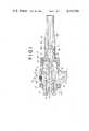
- FIG. 1is a sectional view of a weft inserting nozzle, which is a first embodiment of the present invention
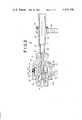
- FIG. 2is a view similar to FIG. 1, but showing a second embodiment of the present invention.
- FIG. 3is a view similar to FIG. 1, but showing a third embodiment of the present invention.
- FIG. 1 of the drawingsthere is shown a first embodiment of the present invention.
- the weft inserting nozzle 10 of the first embodimentcomprises a cylindrical hollow body 12 tightly held by a holder 14.
- Designated by numeral 16is a ring connector which is screwed on the hollow body 12 to assure tight connection between the hollow body 12 and the holder 14.
- the hollow body 12has a longitudinally extending through hole which consists of a larger diameter section and a smaller diameter section.
- Screwed into the through hole of the hollow body 12is a weft inserting body 18 which has a longitudinally extending passage 20 (or first weft inserting hole A) through which a weft yarn W is to be passed.
- the entrance of the passage 20is formed into a frustoconical shape for achieving easy and reliable insertion of the weft yarn thereinto.
- the weft inserting body 18includes a large diameter section preferably screwed to the larger diameter section of the hollow body through hole, a medium diameter section spacedly disposed within the remaining part of the larger diameter section of the hollow body through hole, and a smaller diameter section spacedly disposed within the smaller diameter section of the hollow body through hole.
- first and second tubular spaces 22 and 24there are formed mutually-communicating first and second tubular spaces 22 and 24 around the medium and smaller diameter sections of the weft inserting body 18, respectively.
- the smaller diameter section of the weft inserting body 18is so positioned as to leave a considerable space 25 between the tip thereof and the exit of the smaller diameter section of the through hole of the hollow body 12.
- Equally spaced air stabilizers 26are provided on the medium diameter section of the weft inserting body 18.
- the cylindrical hollow body 12is formed about the outer surface thereof with an annular groove 28 which communicates with the first tubular space 22 through a plurality of radial holes 30 formed in the hollow body 12.
- the annular groove 28is connected to an air supply source (not shown) through an opening 32 formed in the holder 14, so that pressurized air from the air source is supplied to the groove 28 and thus to the second tubular space 24.
- an air supply sourcenot shown
- a tubular body 34 having a longitudinally extending through hole 36is connected to the hollow body 12 in a manner to coaxially extend therefrom. As shown, the connection between them is such made that a sleeve-shaped tip portion of the hollow body 12 is snugly received in an enlarged entrance section of the tubular body through hole 36.
- Designated by numeral 38is a coupler for securing the tubular body 34 to the hollow body 12. It is to be noted that the hole 25 of the hollow body 12 and the hole 36 of the tubular body 34 constitute a second weft inserting hole C which will be described hereinafter.
- the hole 36 of the tubular body 34has at its upstream part a first section 36a which has the same diameter as that of the hole 25 of the hollow body 12, and at its downstream part a second section 36b which has a larger diameter than the first section 36a.
- Designated by numeral 40is a stepped portion from which the second section 36b extends.
- pressurized air from the air supply sourceis intermittently supplied to the second tubular space 24 through the annular groove 28, the radial holes 30, the first annular space 22 and the air stabilizers 26.
- the pressurized air thus reaching the second tubular space 24is ejected or jetted from the air jet opening B toward the second weft inserting hole C. With this air jet, the weft yarn W in the first weft inserting hole A is drawn downstream toward the second weft inserting hole C.
- FIG. 2there is shown a second embodiment of the present invention.
- the nozzle 10' of this embodimenthas substantially the same construction and parts as those of the first embodiment except for the construction of the tubular body 34'.
- a plurality of air introducing holes 42are formed in the tubular body 34' in a manner to diagonally extend from the stepped portion 40' to the other surface of the body 34'.
- Each hole 42is inclined upstream with respect to the axis of the second weft inserting hole C'.
- FIG. 3there is shown a third embodiment of the present invention.
- the nozzle 10" of this embodimentis a modification of the nozzle 10' of the second embodiment.
- a separate tubular body 34" having a straight through hole 36"is tightly held by a holder 44.
- Designated by numeral 48is a ring connector for securing the tubular body 34" to the holder 44.
- the through hole 36" of the tubular body 34"has throughout the whole length thereof a uniform diameter larger than that of the smaller diameter section of the hollow body 12.
- the sleeve-shaped tip portion of the hollow body 12is spacedly disposed in the entrance of the tubular body's through hole 36", leaving an annular clearance 46 therebetween.
- the hole 25 of the hollow body 12 and the hole 36" of the tubular body 34"constitute the second weft inserting hole C". With this construction, substantially the same effect as that of the second embodiment is achieved.
Landscapes
- Engineering & Computer Science (AREA)
- Textile Engineering (AREA)
- Looms (AREA)
Abstract
Description
Claims (1)
Applications Claiming Priority (2)
| Application Number | Priority Date | Filing Date | Title |
|---|---|---|---|
| JP55142927AJPS5771445A (en) | 1980-10-15 | 1980-10-15 | Wefting nozzle of air jet type loom |
| JP55-142927 | 1980-10-15 |
Publications (1)
| Publication Number | Publication Date |
|---|---|
| US4433706Atrue US4433706A (en) | 1984-02-28 |
Family
ID=15326864
Family Applications (1)
| Application Number | Title | Priority Date | Filing Date |
|---|---|---|---|
| US06/306,299Expired - LifetimeUS4433706A (en) | 1980-10-15 | 1981-09-28 | Weft inserting nozzle of an air jet type weaving loom |
Country Status (7)
| Country | Link |
|---|---|
| US (1) | US4433706A (en) |
| JP (1) | JPS5771445A (en) |
| KR (1) | KR840001520B1 (en) |
| DE (1) | DE3138081C2 (en) |
| FR (1) | FR2491962B1 (en) |
| GB (1) | GB2085487B (en) |
| IT (1) | IT1171584B (en) |
Cited By (7)
| Publication number | Priority date | Publication date | Assignee | Title |
|---|---|---|---|---|
| US4877063A (en)* | 1986-12-02 | 1989-10-31 | Picanol N.V. | Main injector with increased tensioning force, for airjet weaving machines |
| EP1275760A3 (en)* | 2001-07-11 | 2004-01-14 | Kabushiki Kaisha Toyota Jidoshokki | Weft conveying nozzle in an air jet loom |
| CN101135080B (en)* | 2006-08-31 | 2011-01-12 | 津田驹工业株式会社 | Weft insertion nozzles for fluid jet looms |
| CN102747513A (en)* | 2012-07-11 | 2012-10-24 | 江苏万工科技集团有限公司 | Main jet guide spray pipe and double-spray main jet composed of same |
| CN103603125A (en)* | 2013-12-10 | 2014-02-26 | 苏州大学 | Main nozzle structure of air jet loom and method for accelerating air flow inside main nozzle |
| CN106743674A (en)* | 2017-02-28 | 2017-05-31 | 中国空气动力研究与发展中心高速空气动力研究所 | A kind of device that solid powder is sent into high velocity air |
| CN107475869A (en)* | 2017-07-22 | 2017-12-15 | 南通唐盛纺织有限公司 | The energy-saving main burner of used in jet loom |
Families Citing this family (8)
| Publication number | Priority date | Publication date | Assignee | Title |
|---|---|---|---|---|
| JPS584851A (en)* | 1981-07-02 | 1983-01-12 | 日産自動車株式会社 | Wefting nozzle of air jet type loom |
| US4494888A (en)* | 1981-07-27 | 1985-01-22 | Seisakusho Kabushiki Kaisha Toyoda Jidoshokki | Weft inserting method and apparatus for an air jet loom |
| JPS60181345A (en)* | 1984-02-24 | 1985-09-17 | 株式会社豊田自動織機製作所 | Wefting apparatus in fluid jet type loom |
| EP0308930A1 (en)* | 1987-09-24 | 1989-03-29 | ELITEX koncern textilniho strojirenstvi | Nozzle for the pneumatic thread transport in a textile machine |
| DE19511439C1 (en)* | 1995-03-29 | 1996-03-14 | Dornier Gmbh Lindauer | System to increase productivity of jet loom |
| BE1012494A3 (en)* | 1999-03-02 | 2000-11-07 | Picanol Nv | Device for the insertion of a weft thread. |
| BE1013786A6 (en)* | 2000-10-24 | 2002-08-06 | Picanol Nv | Guide tube for a head and main blower blower. |
| KR20030060211A (en)* | 2002-01-07 | 2003-07-16 | 김정선 | Injection nozzle with air injection ball for water jet loom |
Citations (8)
| Publication number | Priority date | Publication date | Assignee | Title |
|---|---|---|---|---|
| GB934535A (en) | 1959-07-13 | 1963-08-21 | Sdruzeni Podniku Textilniho St | Improvements in or relating to jet looms |
| GB1213992A (en) | 1967-09-26 | 1970-11-25 | Strake Maschf Nv | Improvements in jet looms |
| GB1289013A (en) | 1969-07-18 | 1972-09-13 | ||
| GB1459707A (en) | 1974-04-10 | 1976-12-31 | Elitex Zavody Textilniho | Nozzle for jet looms |
| GB1544484A (en) | 1975-10-02 | 1979-04-19 | Elitex Zavody Textilniho | Nozzle assembly for use in hydraulic jet looms |
| US4347872A (en) | 1979-08-06 | 1982-09-07 | Leesona Corporation | Air weft insertion system |
| GB2012322B (en) | 1978-01-06 | 1982-09-08 | Nissan Motor | Weft picking device of air jet type weaving loom |
| US4353397A (en) | 1979-06-01 | 1982-10-12 | Ishikawa Seisakusho Ltd. | Apparatus for inserting a weft on an air jet loom |
Family Cites Families (3)
| Publication number | Priority date | Publication date | Assignee | Title |
|---|---|---|---|---|
| US4105053A (en)* | 1975-10-02 | 1978-08-08 | Elitex, Koncern Textilniho Strojirenstvi | Nozzle assembly for a hydraulic jet loom |
| DE2911862A1 (en)* | 1979-03-13 | 1980-09-25 | Sulzer Ag | NOZZLE ARRANGEMENT FOR A WEAVING MACHINE WITH BEAM ENTRY |
| EP0023928B1 (en)* | 1979-08-08 | 1983-05-18 | GebràDer Sulzer Aktiengesellschaft | Nozzle arrangement for a jet loom |
- 1980
- 1980-10-15JPJP55142927Apatent/JPS5771445A/enactivePending
- 1981
- 1981-07-22KRKR1019810002659Apatent/KR840001520B1/ennot_activeExpired
- 1981-09-16GBGB8127958Apatent/GB2085487B/ennot_activeExpired
- 1981-09-24DEDE3138081Apatent/DE3138081C2/ennot_activeExpired
- 1981-09-28USUS06/306,299patent/US4433706A/ennot_activeExpired - Lifetime
- 1981-10-13ITIT49474/81Apatent/IT1171584B/enactive
- 1981-10-14FRFR8119349Apatent/FR2491962B1/ennot_activeExpired
Patent Citations (8)
| Publication number | Priority date | Publication date | Assignee | Title |
|---|---|---|---|---|
| GB934535A (en) | 1959-07-13 | 1963-08-21 | Sdruzeni Podniku Textilniho St | Improvements in or relating to jet looms |
| GB1213992A (en) | 1967-09-26 | 1970-11-25 | Strake Maschf Nv | Improvements in jet looms |
| GB1289013A (en) | 1969-07-18 | 1972-09-13 | ||
| GB1459707A (en) | 1974-04-10 | 1976-12-31 | Elitex Zavody Textilniho | Nozzle for jet looms |
| GB1544484A (en) | 1975-10-02 | 1979-04-19 | Elitex Zavody Textilniho | Nozzle assembly for use in hydraulic jet looms |
| GB2012322B (en) | 1978-01-06 | 1982-09-08 | Nissan Motor | Weft picking device of air jet type weaving loom |
| US4353397A (en) | 1979-06-01 | 1982-10-12 | Ishikawa Seisakusho Ltd. | Apparatus for inserting a weft on an air jet loom |
| US4347872A (en) | 1979-08-06 | 1982-09-07 | Leesona Corporation | Air weft insertion system |
Non-Patent Citations (1)
| Title |
|---|
| Journal of the Textile Machine Society of Japan, Jul. 1961, A Study on Air-Jet Looms, Minoru Uno et al. |
Cited By (9)
| Publication number | Priority date | Publication date | Assignee | Title |
|---|---|---|---|---|
| US4877063A (en)* | 1986-12-02 | 1989-10-31 | Picanol N.V. | Main injector with increased tensioning force, for airjet weaving machines |
| EP1275760A3 (en)* | 2001-07-11 | 2004-01-14 | Kabushiki Kaisha Toyota Jidoshokki | Weft conveying nozzle in an air jet loom |
| CN101135080B (en)* | 2006-08-31 | 2011-01-12 | 津田驹工业株式会社 | Weft insertion nozzles for fluid jet looms |
| CN102747513A (en)* | 2012-07-11 | 2012-10-24 | 江苏万工科技集团有限公司 | Main jet guide spray pipe and double-spray main jet composed of same |
| CN103603125A (en)* | 2013-12-10 | 2014-02-26 | 苏州大学 | Main nozzle structure of air jet loom and method for accelerating air flow inside main nozzle |
| CN103603125B (en)* | 2013-12-10 | 2015-10-28 | 苏州大学 | Air-flow accelerated method in a kind of main nozzle structure of air-jet loom and main burner |
| CN106743674A (en)* | 2017-02-28 | 2017-05-31 | 中国空气动力研究与发展中心高速空气动力研究所 | A kind of device that solid powder is sent into high velocity air |
| CN106743674B (en)* | 2017-02-28 | 2022-12-23 | 中国空气动力研究与发展中心高速空气动力研究所 | Device for feeding solid powder into high-speed airflow |
| CN107475869A (en)* | 2017-07-22 | 2017-12-15 | 南通唐盛纺织有限公司 | The energy-saving main burner of used in jet loom |
Also Published As
| Publication number | Publication date |
|---|---|
| KR830006502A (en) | 1983-09-24 |
| DE3138081A1 (en) | 1982-05-13 |
| JPS5771445A (en) | 1982-05-04 |
| DE3138081C2 (en) | 1985-06-13 |
| GB2085487B (en) | 1984-04-11 |
| FR2491962B1 (en) | 1986-03-14 |
| KR840001520B1 (en) | 1984-09-29 |
| GB2085487A (en) | 1982-04-28 |
| IT8149474A0 (en) | 1981-10-13 |
| FR2491962A1 (en) | 1982-04-16 |
| IT1171584B (en) | 1987-06-10 |
Similar Documents
| Publication | Publication Date | Title |
|---|---|---|
| US4433706A (en) | Weft inserting nozzle of an air jet type weaving loom | |
| US3847187A (en) | Weft inserting channel for pneumatic weaving machines | |
| US5526850A (en) | Main nozzle accelerator chamber for an air-jet loom | |
| US4369817A (en) | Weft picking device of air jet type weaving loom | |
| US3402446A (en) | Apparatus for bulking yarn | |
| GB2088911A (en) | A method for conveying a flexible thread by means of a pressurized gas | |
| US4457346A (en) | Weft inserting nozzle of an air-jet type weaving loom | |
| US3999579A (en) | Weft ejection nozzle for water jet looms | |
| US4552188A (en) | Weft inserting device | |
| US4353397A (en) | Apparatus for inserting a weft on an air jet loom | |
| JPS5945773B2 (en) | Air injection loom weft insertion device | |
| US4392517A (en) | Weft picking method and device for carrying out same | |
| JP6039031B2 (en) | Injection nozzle for water jet loom | |
| US4433705A (en) | Picking channel for a jet loom | |
| US4877063A (en) | Main injector with increased tensioning force, for airjet weaving machines | |
| JPS6226461Y2 (en) | ||
| GB2097828A (en) | Weft inserting channel in jet weaving machines | |
| GB2144776A (en) | Jet looms | |
| SU1087582A1 (en) | Receiving rapier of air-needle weaving machine | |
| JPS5865039A (en) | Wefting nozzle of air jet type loom | |
| JPS6021943A (en) | Plural yarn selecting wefting apparatus of air jet type loom | |
| JPS6011112Y2 (en) | Weft insertion device in air jet trum | |
| JPS63772Y2 (en) | ||
| JPS6014138B2 (en) | Weft insertion method and equipment in air jet trum | |
| JPH01162844A (en) | Nozzle for air jet loom |
Legal Events
| Date | Code | Title | Description |
|---|---|---|---|
| AS | Assignment | Owner name:NISSAN MOTOR CO., LTD., NO. 2, TAKARA-CHO, KANAGAW Free format text:ASSIGNMENT OF ASSIGNORS INTEREST.;ASSIGNORS:TAKAHASHI, TAKAO;OHNISHI, KIMIMASA;WAKAI, SINZI;REEL/FRAME:003933/0593 Effective date:19810831 | |
| STCF | Information on status: patent grant | Free format text:PATENTED CASE | |
| MAFP | Maintenance fee payment | Free format text:PAYMENT OF MAINTENANCE FEE, 4TH YEAR, PL 96-517 (ORIGINAL EVENT CODE: M170); ENTITY STATUS OF PATENT OWNER: LARGE ENTITY Year of fee payment:4 | |
| MAFP | Maintenance fee payment | Free format text:PAYMENT OF MAINTENANCE FEE, 8TH YEAR, PL 96-517 (ORIGINAL EVENT CODE: M171); ENTITY STATUS OF PATENT OWNER: LARGE ENTITY Year of fee payment:8 | |
| FEPP | Fee payment procedure | Free format text:PAYOR NUMBER ASSIGNED (ORIGINAL EVENT CODE: ASPN); ENTITY STATUS OF PATENT OWNER: LARGE ENTITY | |
| MAFP | Maintenance fee payment | Free format text:PAYMENT OF MAINTENANCE FEE, 12TH YEAR, LARGE ENTITY (ORIGINAL EVENT CODE: M185); ENTITY STATUS OF PATENT OWNER: LARGE ENTITY Year of fee payment:12 | |
| AS | Assignment | Owner name:KABUSHIKI KAISHA TOYODA JIDOSHOKKI SEISAKUSHO, JAP Free format text:ASSIGNMENT OF ASSIGNORS INTEREST;ASSIGNOR:NISSAN MOTOR CO., LTD.;REEL/FRAME:010281/0312 Effective date:19990818 |