US4433627A - Plastic conveyor trolley with bearings - Google Patents
Plastic conveyor trolley with bearingsDownload PDFInfo
- Publication number
- US4433627A US4433627AUS06/287,884US28788481AUS4433627AUS 4433627 AUS4433627 AUS 4433627AUS 28788481 AUS28788481 AUS 28788481AUS 4433627 AUS4433627 AUS 4433627A
- Authority
- US
- United States
- Prior art keywords
- trolley
- stub axle
- wheel
- plastic
- upper portion
- Prior art date
- Legal status (The legal status is an assumption and is not a legal conclusion. Google has not performed a legal analysis and makes no representation as to the accuracy of the status listed.)
- Expired - Fee Related
Links
- 239000004033plasticSubstances0.000titleclaimsabstractdescription33
- 229920003023plasticPolymers0.000titleclaimsabstractdescription33
- 239000002991molded plasticSubstances0.000claims3
- 230000000717retained effectEffects0.000claims2
- 239000000463materialSubstances0.000abstractdescription13
- 239000002184metalSubstances0.000abstractdescription3
- 230000000295complement effectEffects0.000abstract1
- 229910000831SteelInorganic materials0.000description9
- 238000010276constructionMethods0.000description9
- 239000010959steelSubstances0.000description9
- 239000004677NylonSubstances0.000description8
- 229920001778nylonPolymers0.000description8
- 229920006102Zytel®Polymers0.000description6
- 230000000712assemblyEffects0.000description6
- 238000000429assemblyMethods0.000description6
- 238000009434installationMethods0.000description5
- 230000008901benefitEffects0.000description4
- 238000005461lubricationMethods0.000description4
- 229920004943Delrin®Polymers0.000description3
- WSFSSNUMVMOOMR-UHFFFAOYSA-NFormaldehydeChemical compoundO=CWSFSSNUMVMOOMR-UHFFFAOYSA-N0.000description3
- 239000011152fibreglassSubstances0.000description3
- 238000012423maintenanceMethods0.000description3
- DHKHKXVYLBGOIT-UHFFFAOYSA-N1,1-DiethoxyethaneChemical compoundCCOC(C)OCCDHKHKXVYLBGOIT-UHFFFAOYSA-N0.000description2
- 239000011354acetal resinSubstances0.000description2
- 238000005265energy consumptionMethods0.000description2
- 239000000314lubricantSubstances0.000description2
- 239000000088plastic resinSubstances0.000description2
- 229920006324polyoxymethylenePolymers0.000description2
- 230000009467reductionEffects0.000description2
- 239000011347resinSubstances0.000description2
- 229920005989resinPolymers0.000description2
- 239000013585weight reducing agentSubstances0.000description2
- 229910019142PO4Inorganic materials0.000description1
- 239000000654additiveSubstances0.000description1
- 230000000996additive effectEffects0.000description1
- 230000015556catabolic processEffects0.000description1
- 239000003518causticsSubstances0.000description1
- 239000012141concentrateSubstances0.000description1
- 239000000356contaminantSubstances0.000description1
- 230000007797corrosionEffects0.000description1
- 238000005260corrosionMethods0.000description1
- 229920001887crystalline plasticPolymers0.000description1
- 238000013461designMethods0.000description1
- 238000005553drillingMethods0.000description1
- 230000000694effectsEffects0.000description1
- 230000008030eliminationEffects0.000description1
- 238000003379elimination reactionMethods0.000description1
- 235000013305foodNutrition0.000description1
- 238000004519manufacturing processMethods0.000description1
- 230000007246mechanismEffects0.000description1
- 238000012986modificationMethods0.000description1
- 230000004048modificationEffects0.000description1
- 230000002093peripheral effectEffects0.000description1
- NBIIXXVUZAFLBC-UHFFFAOYSA-KphosphateChemical compound[O-]P([O-])([O-])=ONBIIXXVUZAFLBC-UHFFFAOYSA-K0.000description1
- 239000010452phosphateSubstances0.000description1
- 238000006116polymerization reactionMethods0.000description1
- 238000012545processingMethods0.000description1
- 235000021067refined foodNutrition0.000description1
- 230000000284resting effectEffects0.000description1
- 239000000126substanceSubstances0.000description1
- 238000013519translationMethods0.000description1
Images

Classifications
- B—PERFORMING OPERATIONS; TRANSPORTING
- B61—RAILWAYS
- B61B—RAILWAY SYSTEMS; EQUIPMENT THEREFOR NOT OTHERWISE PROVIDED FOR
- B61B13/00—Other railway systems
- B61B13/04—Monorail systems
- Y—GENERAL TAGGING OF NEW TECHNOLOGICAL DEVELOPMENTS; GENERAL TAGGING OF CROSS-SECTIONAL TECHNOLOGIES SPANNING OVER SEVERAL SECTIONS OF THE IPC; TECHNICAL SUBJECTS COVERED BY FORMER USPC CROSS-REFERENCE ART COLLECTIONS [XRACs] AND DIGESTS
- Y02—TECHNOLOGIES OR APPLICATIONS FOR MITIGATION OR ADAPTATION AGAINST CLIMATE CHANGE
- Y02T—CLIMATE CHANGE MITIGATION TECHNOLOGIES RELATED TO TRANSPORTATION
- Y02T30/00—Transportation of goods or passengers via railways, e.g. energy recovery or reducing air resistance
Definitions
- conveyor chain-driven trolleyshave been made of steel and metallic components requiring considerable and expensive lubrication installations and maintenance.
- Such trolleysare of very substantial weight, adding materially to the load on the conveyor and consequent high energy consumption, having a relatively short service life before replacement or service maintenance is required, readily subject to corrosion and early failure in certain chemically active environments, and having other limitations which the instant invention avoids.
- the plastic trolley construction of this inventionis extremely advantageous in areas where severely corrosive chemical vapors are present, such for example where caustic wash solutions are sprayed, causing a breakdown in lubrication which in turn destroys the roller bearings in the present steel trolley assemblies.
- the same resultsoccur in the presence of phosphate solutions. Millions of dollars are being spent to automatically lubricate overhead monorail conveyor systems and to seal off the trolley assemblies while they pass through these severely corrosive areas.
- the inventive trolley constructionpermits lower replacement cost for any component. This is not true for the presently used steel assemblies. For example, if a steel ball bearing trolley wheel should fail, not only the wheel but the entire side arm must be replaced. In the instant invention, the individual unitary components are simply and readily replaceable, at a very substantially lower cost.
- the plastic trolley construction of this inventionhas some additional advantages.
- the plastic conveyor trolley with roller bearingsreduces the initial drag of the plastic stub axle and wheel combination on start-up of the conveyor system. Only line, not surface contact, is made by the plastic roller bearings on the plastic stub axle and plastic wheel, thereby significantly reducing the initial pull load of the conveyor system.
- Color coding of the plastic trolley assemblieswill enable part identification to be more readily made on mixed model conveyor installations. Also, the assemblies can be colored brightly to signal a moving object, even though color coding may not be required under OSHA specifications.
- the trolley arms, stub axle, roller bearings, wheels and pendant memberare each engineered to be readily replaceable in minutes, resulting in minimum downtime of the conveyor system.
- the Zytel®ST 801 plastic nylon materialused in the fabrication of applicant's trolley components, is a super tough nylon resin material produced by E. I. DuPont de Nemours & Co. (Inc.) of Wilmington, Del. 19898. Another material which can be used for the roller bearings is DuPont's Delrin® crystalline plastic, an acetal resin material made by the polymerization of formaldehyde.
- the Zytel® plastic resincan be mixed with a fiber glass concentrate to add further strength to the nylon material. The amount of such fiber glass additive is proportional to the weight load of the conveyor trolley assembly. As the load or weight requirements of the trolley assembly increase, the percentage of fiber glass used with the nylon resin is also increased.
- the inventioninvolves a conveyor trolley construction comprising a pair of plastic trolley arms arranged in opposed facing relationship, a plastic trolley wheel removably mounted for free rotation upon a plastic stub axle removably secured to the inner face of each trolley arm, a plurality of plastic roller bearings radially disposed in axially parallel relationship to and upon the perimeter of the stub axle, and a depending plastic member removably secured to the lower ends of the trolley arms therebetween.
- the trolley wheelsare designed to run upon the lower or upper horizontal flanges of a conveyor-type I-beam monorail.
- the stub axles supporting the trolley wheels for rotation thereonare removably secured to the trolley arms by screws passed through openings in the arms from their outer sides.
- the roller bearingsrotate in axially parallel recesses at the perimeter of the stub axle.
- the plastic depending memberdesigned for suspending a parts hanger therefrom, is disposed between and secured to the lower portions of the trolley arms and below the I-beam flanges, by screws.
- the conveyor drive chainformed of a series of links, engage and are connected to the depending member to draw the trolley assembly along and upon the monorail flanges.
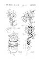
- FIG. 1is a perspective view of the conveyor trolley construction embodying a preferred form of the invention.
- FIG. 2is an exploded perspective view of the embodiment illustrated in FIG. 1.
- FIG. 3is a front or outer elevational view of the trolley arm and wheel assembly.
- FIG. 4is a vertical section view of the trolley arm taken substantially on the line 4--4 of FIG. 3.
- FIG. 5is a side elevational view of the trolley arm and wheel assembly illustrated in FIGS. 3 and 4.
- FIG. 6is an elevational view of the arm and wheel assembly taken substantially on the line 6--6 of FIG. 5.
- FIG. 7is a vertical sectional view taken substantially on the line 7--7 of FIG. 4.
- FIG. 8is a side elevational view of the stub axle illustrated in FIG. 7.
- the plastic conveyor trolley with bearings construction 10comprises a pair of trolley arms 12, 14 (left- and right-hand), a pair of trolley wheels 16, 18 for the respective trolley arms, a pair of stub axles 20, 22 for the respective wheels, a plurality of plastic roller bearings 26 rotatable in recesses of the stub axles, and a pendant member 24.
- the trolley assembly 10is designed to operate upon an I-beam monorail 30 having upper horizontally disposed flanges 32, 34 and lower horizontally disposed flanges 36, 38, and a vertical web 40 therebetween.
- the inner surfaces of these flangesare disposed at a slight angle to the horizontal plane, as shown in FIGS. 1 and 4.
- the outer surface of the trolley wheels engaging the monorail flange surfaces, the axial attitude of the stub axle and the vertical attitude of that portion of the trolley arm supporting the stub axle and the trolley wheelare canted outwardly to compensate for the angle of those flange surfaces.
- the trolley assemblies 10are propelled along the monorail 30 by a conventional conveyor drive chain 48 having links which engage the trolley assembly at the pendant member 24.
- the trolley arms 12, 14are substantially identical so that they can be used as either a left-hand or right-hand element.
- the armcomprises a body 52 having a stub axle support portion 54, an intermediate web section 56, a lower pendant portion 58, and a peripheral rim or flange 60.
- the stub axle support portion 54is provided with a recess or counterbore 61 to seat the stub axle 20 or 22.
- Some two or three holes 62are disposed through the support portion 54 for screws 64 which engage and secure the stub axle 20 or 22 to the body support portion 54.
- the pendant portion 58is also provided with a pair of holes 66, 66 through which screws 68, 68 are passed to secure the pendant member 24 therebetween.
- the inner surface of the trolley arms 12, 14 in the pendant portion 58is provided with a pair of outwardly projecting spaced apart flanges or ribs 70, 70 that engage the pendant member 24 laterally and prevent it from rotation about the screws 68, 68.
- the stub axles 20, 22are substantially identical and each comprise a hub section 76 and a radially outwardly extending flange 78 at the distal end of the hub section, as shown particularly in FIGS. 4 and 8.
- the hub sectionis provided with threaded holes 80 to receive and engage the screws 64 passed through the axle support portion holes 62 from the outer side of the axle support portion 54.
- the hub section 76is further provided with a plurality of longitudinally extending arcuate notches or recesses 82 disposed in axially parallel and spaced substantially equally radially apart relationship in its perimeter 84.
- the recesses 82extend from the proximal end of the stub axle hub section, as shown clearly in FIGS. 1, 7 and 8.
- the plastic roller bearings 26lie in these recesses (FIG. 7), and rotate therein when engaged by body 86 of wheel 16 or 18 at its bore 90.
- the bearings 26are slightly shorter in length, by approximately 1/32 inch, than the length of the recesses 82 in which they lie.
- the bearingshave a slightly smaller diameter, approximately 0.010-0.015 inch, than the diametric dimension of the recesses, whereby each bearing ideally makes a line contact with the recess surface in which it lies and rotates.
- the stub axle section 76 with its recesses 82thus functions as a support bearing or fixed race for the roller bearings 26, as shown particularly clearly in FIGS. 2, 4 and 7.
- the trolley wheels 16, 18are substantially identical and each comprise a body 86, an annular flange 88 on its rearward side, a bore 90 for the stub axle hub portion 76, and a counterbore 92 for the stub axle outer flange 78.
- the outer annular surface 94 of the wheelis tapered so as to ride in a vertical attitude upon the upper surfaces of the monorail lower flanges 36, 38 and the lower surfaces of the upper flanges 32, 34.
- the frictional coefficient of the Zytel®ST nylon material or the Delrin® acetal resin materialis low and lubricant for the bearings or the wheel is not required.
- the upper portion of the pendant member 24is first passed through the drive chain linkage until the intermediate ribs abut the drive chain link.
- the trolley arms 12, 14, with wheels 16, 18 disposed on their respective stub axles 20, 22 and about the bearings 26 therewithin,are then attached to the pendant member 24 on each side thereof by screws 68, 68, wheels 16, 18 resting upon the upper surfaces of the I-beam monorail lower flanges 36, 38.
- the annular flange 78thus functions as a retainer for the trolley wheel 16/18, as shown clearly in FIGS. 2 and 4.
- a hanger devicecan be suspended from and attached to the lower end of the pendant member 24.
- screws 64 at the outer side of each trolley armare removed from its stub axle, allowing the wheels, stub axles, and bearings to simply part from the arms.
- Each of the principal components of the trolley structure 10are molded of the Zytel®ST 801 nylon material, the bearings being preferably molded or extruded of Zytel® or Delrin® plastic material.
- the fastening screws 64 and 68preferably of metal, may also be made of a suitable plastic material to meet the needs of certain applications.
Landscapes
- Engineering & Computer Science (AREA)
- Transportation (AREA)
- Mechanical Engineering (AREA)
- Chain Conveyers (AREA)
- Carriers, Traveling Bodies, And Overhead Traveling Cranes (AREA)
Abstract
Description
Claims (8)
Priority Applications (6)
| Application Number | Priority Date | Filing Date | Title |
|---|---|---|---|
| US06/287,884US4433627A (en) | 1981-07-29 | 1981-07-29 | Plastic conveyor trolley with bearings |
| DE19823227736DE3227736A1 (en) | 1981-07-29 | 1982-07-24 | Trolley |
| JP57129502AJPS5842510A (en) | 1981-07-29 | 1982-07-24 | Assembled body of trolley |
| CA000408289ACA1179960A (en) | 1981-07-29 | 1982-07-28 | Plastic conveyor trolley with bearings |
| FR8213178AFR2510504A1 (en) | 1981-07-29 | 1982-07-28 | TROLLEY FOR CONVEYOR MONORAIL A BEAM IN I |
| GB08221749AGB2104467B (en) | 1981-07-29 | 1982-07-28 | Overhead i-beam conveyor trolley assembly |
Applications Claiming Priority (1)
| Application Number | Priority Date | Filing Date | Title |
|---|---|---|---|
| US06/287,884US4433627A (en) | 1981-07-29 | 1981-07-29 | Plastic conveyor trolley with bearings |
Publications (1)
| Publication Number | Publication Date |
|---|---|
| US4433627Atrue US4433627A (en) | 1984-02-28 |
Family
ID=23104787
Family Applications (1)
| Application Number | Title | Priority Date | Filing Date |
|---|---|---|---|
| US06/287,884Expired - Fee RelatedUS4433627A (en) | 1981-07-29 | 1981-07-29 | Plastic conveyor trolley with bearings |
Country Status (6)
| Country | Link |
|---|---|
| US (1) | US4433627A (en) |
| JP (1) | JPS5842510A (en) |
| CA (1) | CA1179960A (en) |
| DE (1) | DE3227736A1 (en) |
| FR (1) | FR2510504A1 (en) |
| GB (1) | GB2104467B (en) |
Cited By (21)
| Publication number | Priority date | Publication date | Assignee | Title |
|---|---|---|---|---|
| US4617867A (en)* | 1983-11-25 | 1986-10-21 | Stellana Plast Ab | Trolley bracket |
| US4619222A (en)* | 1983-06-07 | 1986-10-28 | Hb Autonom | Animal training course, especially for race horses |
| USD291138S (en) | 1984-03-23 | 1987-07-28 | Stellana Plast Ab | Bracket for use in a trolley member |
| US4858752A (en)* | 1988-02-04 | 1989-08-22 | Dynamic Conveyor Products | Wheel assembly for conveyer system |
| US4987638A (en)* | 1988-05-05 | 1991-01-29 | Nickolas Ribaudo | Sliding door assembly |
| US5357868A (en)* | 1992-04-21 | 1994-10-25 | Tama Plastic Industry | Trolley apparatus with reinforced plastic wheels and interlocking plastic bushings |
| US5363770A (en)* | 1992-05-19 | 1994-11-15 | Daifuku Co., Ltd. | Drive unit for transport trolley having plastic center link and drive dog covering for noise reduction |
| US5398618A (en)* | 1991-02-26 | 1995-03-21 | Vfv Polymers Pty. Ltd. | Conveyor trolley wheel assembly |
| WO2001038204A1 (en) | 1999-11-24 | 2001-05-31 | Hoffmann Frank F | Conveyor components |
| US6241082B1 (en)* | 1999-05-03 | 2001-06-05 | Cersa N.V. Societe Anonyme | Conveyor for use in the automotive industry |
| US20030213093A1 (en)* | 2002-05-16 | 2003-11-20 | Tom Perks | Panel roller |
| US20080210654A1 (en)* | 2006-07-28 | 2008-09-04 | Kouzo Kataoka | Trolley for loading |
| US7775162B1 (en)* | 2006-08-07 | 2010-08-17 | Cislo Lawrence | Roller for trolley assembly |
| US20130075350A1 (en)* | 2011-09-28 | 2013-03-28 | Breakingpoint Systems, Inc. | Devices for facilitating installation and/or removal of components in an equipment rack |
| US20140135133A1 (en)* | 2012-11-15 | 2014-05-15 | Kia Motors Corporation | Constant velocity joint |
| US8733537B2 (en)* | 2012-03-16 | 2014-05-27 | Nhk Spring Co., Ltd. | Guiding apparatus that maintains attitude of suspended object during conveyance |
| US8850659B2 (en)* | 2011-11-03 | 2014-10-07 | K. Bradley Ewing | Top hung sliding panel apparatus and method |
| US9624708B2 (en)* | 2015-03-10 | 2017-04-18 | Ciw Enterprises, Inc. | Closure with roller endlock |
| US9896270B2 (en)* | 2014-05-29 | 2018-02-20 | Esypro Manutención S.L.U. | Flexible manual storage system |
| CN113474265A (en)* | 2019-02-07 | 2021-10-01 | Tgw机械有限公司 | Transport carrier system and overhead conveyor with transport carrier for transporting suspended loads |
| US11565886B2 (en)* | 2020-09-30 | 2023-01-31 | Citic Dicastal Co., Ltd. | Wheel transfer device |
Families Citing this family (5)
| Publication number | Priority date | Publication date | Assignee | Title |
|---|---|---|---|---|
| US4484525A (en)* | 1981-07-06 | 1984-11-27 | Formall Syn-Trac Systems, Inc. | Plastic monorail conveyor trolley |
| FR2557054B1 (en)* | 1983-12-22 | 1987-01-30 | Skirail Ind | DEVICE FOR ROLLING AND GUIDING A FUNICULAR ON RAILS |
| DE4031685C3 (en)* | 1990-10-04 | 2001-11-08 | Mannesmann Ag | Impeller block |
| DE102010048057B4 (en)* | 2010-10-12 | 2013-11-14 | Wolffkran Holding Ag | Trolley made of carbon fiber reinforced plastic |
| CN106276061A (en)* | 2016-08-08 | 2017-01-04 | 上海大学 | A kind of chain overhead conveyor |
Citations (8)
| Publication number | Priority date | Publication date | Assignee | Title |
|---|---|---|---|---|
| US1367706A (en) | 1920-02-11 | 1921-02-08 | Timken Roller Bearing Co | Trolley-wheel bearing |
| US1429118A (en) | 1921-02-04 | 1922-09-12 | Whiting Corp | Trolley |
| US2010362A (en) | 1934-02-12 | 1935-08-06 | Karl L Herrmann | Antifriction bearing |
| US2073131A (en) | 1934-06-13 | 1937-03-09 | Jervis B Webb | Conveyer |
| US2101951A (en) | 1936-06-30 | 1937-12-14 | Mcinnis Colin Herbert | Trolley yoke |
| US2770508A (en) | 1955-03-07 | 1956-11-13 | Mcgill Mfg Company Inc | Cam follower bearing |
| GB1380363A (en) | 1971-03-17 | 1975-01-15 | Skf Ind Trading & Dev | Bearing capable of accommodating rotational oscillations |
| US4228738A (en) | 1978-09-22 | 1980-10-21 | Forshee David J | Conveyor trolley construction |
Family Cites Families (4)
| Publication number | Priority date | Publication date | Assignee | Title |
|---|---|---|---|---|
| GB1052451A (en)* | 1962-10-23 | 1900-01-01 | ||
| GB1029341A (en)* | 1964-02-19 | 1966-05-11 | Gen Electric Co Ltd | Improvements in or relating to bearings |
| GB1201524A (en)* | 1968-05-24 | 1970-08-05 | Stewart Gill & Company Ltd | Improvements in or relating to wheels and rollers for conveyors |
| GB2111928B (en)* | 1981-12-24 | 1985-05-09 | Autochick Limited | Load supporting carrier adapted to run on an overhead track |
- 1981
- 1981-07-29USUS06/287,884patent/US4433627A/ennot_activeExpired - Fee Related
- 1982
- 1982-07-24JPJP57129502Apatent/JPS5842510A/enactivePending
- 1982-07-24DEDE19823227736patent/DE3227736A1/ennot_activeWithdrawn
- 1982-07-28CACA000408289Apatent/CA1179960A/ennot_activeExpired
- 1982-07-28GBGB08221749Apatent/GB2104467B/ennot_activeExpired
- 1982-07-28FRFR8213178Apatent/FR2510504A1/enactivePending
Patent Citations (8)
| Publication number | Priority date | Publication date | Assignee | Title |
|---|---|---|---|---|
| US1367706A (en) | 1920-02-11 | 1921-02-08 | Timken Roller Bearing Co | Trolley-wheel bearing |
| US1429118A (en) | 1921-02-04 | 1922-09-12 | Whiting Corp | Trolley |
| US2010362A (en) | 1934-02-12 | 1935-08-06 | Karl L Herrmann | Antifriction bearing |
| US2073131A (en) | 1934-06-13 | 1937-03-09 | Jervis B Webb | Conveyer |
| US2101951A (en) | 1936-06-30 | 1937-12-14 | Mcinnis Colin Herbert | Trolley yoke |
| US2770508A (en) | 1955-03-07 | 1956-11-13 | Mcgill Mfg Company Inc | Cam follower bearing |
| GB1380363A (en) | 1971-03-17 | 1975-01-15 | Skf Ind Trading & Dev | Bearing capable of accommodating rotational oscillations |
| US4228738A (en) | 1978-09-22 | 1980-10-21 | Forshee David J | Conveyor trolley construction |
Non-Patent Citations (1)
| Title |
|---|
| DuPont Publication Zytel Nylon Resin, Jul. 16, 1959. |
Cited By (23)
| Publication number | Priority date | Publication date | Assignee | Title |
|---|---|---|---|---|
| US4619222A (en)* | 1983-06-07 | 1986-10-28 | Hb Autonom | Animal training course, especially for race horses |
| US4617867A (en)* | 1983-11-25 | 1986-10-21 | Stellana Plast Ab | Trolley bracket |
| USD291138S (en) | 1984-03-23 | 1987-07-28 | Stellana Plast Ab | Bracket for use in a trolley member |
| US4858752A (en)* | 1988-02-04 | 1989-08-22 | Dynamic Conveyor Products | Wheel assembly for conveyer system |
| US4987638A (en)* | 1988-05-05 | 1991-01-29 | Nickolas Ribaudo | Sliding door assembly |
| US5398618A (en)* | 1991-02-26 | 1995-03-21 | Vfv Polymers Pty. Ltd. | Conveyor trolley wheel assembly |
| US5357868A (en)* | 1992-04-21 | 1994-10-25 | Tama Plastic Industry | Trolley apparatus with reinforced plastic wheels and interlocking plastic bushings |
| US5363770A (en)* | 1992-05-19 | 1994-11-15 | Daifuku Co., Ltd. | Drive unit for transport trolley having plastic center link and drive dog covering for noise reduction |
| US6241082B1 (en)* | 1999-05-03 | 2001-06-05 | Cersa N.V. Societe Anonyme | Conveyor for use in the automotive industry |
| WO2001038204A1 (en) | 1999-11-24 | 2001-05-31 | Hoffmann Frank F | Conveyor components |
| US20030213093A1 (en)* | 2002-05-16 | 2003-11-20 | Tom Perks | Panel roller |
| US20080210654A1 (en)* | 2006-07-28 | 2008-09-04 | Kouzo Kataoka | Trolley for loading |
| US7775162B1 (en)* | 2006-08-07 | 2010-08-17 | Cislo Lawrence | Roller for trolley assembly |
| US20130075350A1 (en)* | 2011-09-28 | 2013-03-28 | Breakingpoint Systems, Inc. | Devices for facilitating installation and/or removal of components in an equipment rack |
| US8850659B2 (en)* | 2011-11-03 | 2014-10-07 | K. Bradley Ewing | Top hung sliding panel apparatus and method |
| US8733537B2 (en)* | 2012-03-16 | 2014-05-27 | Nhk Spring Co., Ltd. | Guiding apparatus that maintains attitude of suspended object during conveyance |
| US20140135133A1 (en)* | 2012-11-15 | 2014-05-15 | Kia Motors Corporation | Constant velocity joint |
| US9086100B2 (en)* | 2012-11-15 | 2015-07-21 | Hyundai Motor Company | Constant velocity joint |
| US9896270B2 (en)* | 2014-05-29 | 2018-02-20 | Esypro Manutención S.L.U. | Flexible manual storage system |
| US9624708B2 (en)* | 2015-03-10 | 2017-04-18 | Ciw Enterprises, Inc. | Closure with roller endlock |
| CN113474265A (en)* | 2019-02-07 | 2021-10-01 | Tgw机械有限公司 | Transport carrier system and overhead conveyor with transport carrier for transporting suspended loads |
| CN113474265B (en)* | 2019-02-07 | 2023-08-11 | Tgw机械有限公司 | Transport carrier system and suspension conveyor with transport carrier for transporting suspended goods |
| US11565886B2 (en)* | 2020-09-30 | 2023-01-31 | Citic Dicastal Co., Ltd. | Wheel transfer device |
Also Published As
| Publication number | Publication date |
|---|---|
| DE3227736A1 (en) | 1983-02-17 |
| FR2510504A1 (en) | 1983-02-04 |
| CA1179960A (en) | 1984-12-27 |
| GB2104467B (en) | 1984-12-19 |
| GB2104467A (en) | 1983-03-09 |
| JPS5842510A (en) | 1983-03-12 |
Similar Documents
| Publication | Publication Date | Title |
|---|---|---|
| US4433627A (en) | Plastic conveyor trolley with bearings | |
| US4228738A (en) | Conveyor trolley construction | |
| CA1043729A (en) | Sanitary trolley wheel | |
| US4484525A (en) | Plastic monorail conveyor trolley | |
| US5156533A (en) | Replaceable plastic trolley wheel and method | |
| US5357868A (en) | Trolley apparatus with reinforced plastic wheels and interlocking plastic bushings | |
| US7063207B2 (en) | Long wear conveyor assembly | |
| RU2141925C1 (en) | Drive system for escalators and moving side-walks | |
| US8702178B2 (en) | Trolley wheel technology | |
| US4993328A (en) | Trolley assembly | |
| US6354677B1 (en) | Bearing for snowmobile track | |
| US5038922A (en) | High speed line shaft conveyor | |
| EP0513271A4 (en) | Sealed roller assembly | |
| US4858752A (en) | Wheel assembly for conveyer system | |
| EP1237803B1 (en) | Conveyor components | |
| EP0054797A1 (en) | Twin wheeled castor | |
| US4685556A (en) | Drive mechanism for a live roller conveyor | |
| US4467913A (en) | Plastic monorail conveyor drive chain wheel | |
| US20240408966A1 (en) | Corrosion-resistant trolley wheel | |
| CA2104687C (en) | Conveyor trolley wheel assembly | |
| RU270U1 (en) | Radial rolling bearing | |
| WO1984000347A1 (en) | Plastic monorail conveyor drive chain linkage | |
| GB2116644A (en) | Guide roller mounting | |
| JPS59501206A (en) | plastic monorail conveyor trolley |
Legal Events
| Date | Code | Title | Description |
|---|---|---|---|
| AS | Assignment | Owner name:FORMALL, INC., 850 SOUTH GLASPIE ROAD, OXFORD, MI Free format text:ASSIGNMENT OF ASSIGNORS INTEREST.;ASSIGNOR:FORSHEE, DAVID J.;REEL/FRAME:003914/0633 Effective date:19811211 Owner name:FORMALL, INC., 850 SOUTH GLASPIE ROAD, OXFORD, MI Free format text:ASSIGNMENT OF ASSIGNORS INTEREST;ASSIGNOR:FORSHEE, DAVID J.;REEL/FRAME:003914/0633 Effective date:19811211 | |
| AS | Assignment | Owner name:FORSHEE, DAVID J. 11 MISTY MORNING DRIVE, HILTON H Free format text:ASSIGNMENT OF ASSIGNORS INTEREST.;ASSIGNOR:FORMALL, INC.;REEL/FRAME:003997/0318 Effective date:19820525 | |
| AS | Assignment | Owner name:SYN-TRAC SYSTEMS INC., 850 SOUTH GLASPIE RD. OXFOR Free format text:ASSIGNMENT OF ASSIGNORS INTEREST.;ASSIGNOR:FORSHEE, DAVID J.;REEL/FRAME:003994/0424 Effective date:19820525 | |
| AS | Assignment | Owner name:FORSHEE, DAVID J. Free format text:ASSIGNMENT OF ASSIGNORS INTEREST.;ASSIGNOR:SYN-TRAC SYSTEMS INC.;REEL/FRAME:004115/0705 Effective date:19830329 | |
| AS | Assignment | Owner name:CAS-TECH, INC. Free format text:ASSIGNMENT OF ASSIGNORS INTEREST.;ASSIGNOR:FORSHEE, DAVID J.;REEL/FRAME:004197/0056 Effective date:19830909 | |
| AS | Assignment | Owner name:CAS-TECH, INC., 1719 WEST END AVE., 5TH FLR., NASH Free format text:ASSIGNMENT OF ASSIGNORS INTEREST.;ASSIGNOR:FORSHEE, DAVID J.;REEL/FRAME:004233/0035 Effective date:19840217 | |
| CC | Certificate of correction | ||
| FEPP | Fee payment procedure | Free format text:MAINTENANCE FEE REMINDER MAILED (ORIGINAL EVENT CODE: REM.); ENTITY STATUS OF PATENT OWNER: LARGE ENTITY | |
| FEPP | Fee payment procedure | Free format text:SURCHARGE FOR LATE PAYMENT, PL 96-517 (ORIGINAL EVENT CODE: M176); ENTITY STATUS OF PATENT OWNER: LARGE ENTITY | |
| MAFP | Maintenance fee payment | Free format text:PAYMENT OF MAINTENANCE FEE, 4TH YEAR, PL 96-517 (ORIGINAL EVENT CODE: M170); ENTITY STATUS OF PATENT OWNER: LARGE ENTITY Year of fee payment:4 | |
| AS | Assignment | Owner name:VCMII SERVICES COMPANY, Free format text:ASSIGNMENT OF ASSIGNORS INTEREST.;ASSIGNOR:COMPOSITE SYSTEMS, INC.,;REEL/FRAME:004835/0781 Effective date:19880225 Owner name:VCMII SERVICES COMPANY,, STATELESS Free format text:ASSIGNMENT OF ASSIGNORS INTEREST;ASSIGNOR:COMPOSITE SYSTEMS, INC.,;REEL/FRAME:004835/0781 Effective date:19880225 | |
| FEPP | Fee payment procedure | Free format text:PAYOR NUMBER ASSIGNED (ORIGINAL EVENT CODE: ASPN); ENTITY STATUS OF PATENT OWNER: LARGE ENTITY | |
| FEPP | Fee payment procedure | Free format text:MAINTENANCE FEE REMINDER MAILED (ORIGINAL EVENT CODE: REM.); ENTITY STATUS OF PATENT OWNER: LARGE ENTITY | |
| LAPS | Lapse for failure to pay maintenance fees | ||
| FP | Lapsed due to failure to pay maintenance fee | Effective date:19920301 | |
| STCH | Information on status: patent discontinuation | Free format text:PATENT EXPIRED DUE TO NONPAYMENT OF MAINTENANCE FEES UNDER 37 CFR 1.362 |