US4433473A - Process for manufacturing a flywheel magneto - Google Patents
Process for manufacturing a flywheel magnetoDownload PDFInfo
- Publication number
- US4433473A US4433473AUS06/283,463US28346381AUS4433473AUS 4433473 AUS4433473 AUS 4433473AUS 28346381 AUS28346381 AUS 28346381AUS 4433473 AUS4433473 AUS 4433473A
- Authority
- US
- United States
- Prior art keywords
- ring
- magnets
- annular ring
- assembly
- sub
- Prior art date
- Legal status (The legal status is an assumption and is not a legal conclusion. Google has not performed a legal analysis and makes no representation as to the accuracy of the status listed.)
- Expired - Fee Related
Links
- 238000000034methodMethods0.000titleclaimsabstractdescription12
- 238000004519manufacturing processMethods0.000titleclaimsabstractdescription8
- 238000005266castingMethods0.000claimsabstractdescription10
- 230000005291magnetic effectEffects0.000claimsabstractdescription9
- 230000004907fluxEffects0.000claimsabstractdescription7
- 239000003302ferromagnetic materialSubstances0.000claimsdescription7
- 238000003754machiningMethods0.000claims3
- 230000015572biosynthetic processEffects0.000claims1
- 239000000463materialSubstances0.000abstractdescription10
- 230000007547defectEffects0.000description3
- 229910010293ceramic materialInorganic materials0.000description2
- 230000005294ferromagnetic effectEffects0.000description2
- 229910045601alloyInorganic materials0.000description1
- 239000000956alloySubstances0.000description1
- 238000001816coolingMethods0.000description1
- 230000001627detrimental effectEffects0.000description1
- 238000005516engineering processMethods0.000description1
- 230000006698inductionEffects0.000description1
- 230000008595infiltrationEffects0.000description1
- 238000001764infiltrationMethods0.000description1
- 229910001092metal group alloyInorganic materials0.000description1
- 239000007769metal materialSubstances0.000description1
- 230000035699permeabilityEffects0.000description1
- 239000012858resilient materialSubstances0.000description1
Images
Classifications
- H—ELECTRICITY
- H02—GENERATION; CONVERSION OR DISTRIBUTION OF ELECTRIC POWER
- H02K—DYNAMO-ELECTRIC MACHINES
- H02K1/00—Details of the magnetic circuit
- H02K1/06—Details of the magnetic circuit characterised by the shape, form or construction
- H02K1/22—Rotating parts of the magnetic circuit
- H02K1/27—Rotor cores with permanent magnets
- H02K1/2786—Outer rotors
- H02K1/2787—Outer rotors the magnetisation axis of the magnets being perpendicular to the rotor axis
- H02K1/2789—Outer rotors the magnetisation axis of the magnets being perpendicular to the rotor axis the rotor consisting of two or more circumferentially positioned magnets
- H02K1/2791—Surface mounted magnets; Inset magnets
- H—ELECTRICITY
- H02—GENERATION; CONVERSION OR DISTRIBUTION OF ELECTRIC POWER
- H02K—DYNAMO-ELECTRIC MACHINES
- H02K15/00—Processes or apparatus specially adapted for manufacturing, assembling, maintaining or repairing of dynamo-electric machines
- H02K15/02—Processes or apparatus specially adapted for manufacturing, assembling, maintaining or repairing of dynamo-electric machines of stator or rotor bodies
- H02K15/03—Processes or apparatus specially adapted for manufacturing, assembling, maintaining or repairing of dynamo-electric machines of stator or rotor bodies having permanent magnets
- Y—GENERAL TAGGING OF NEW TECHNOLOGICAL DEVELOPMENTS; GENERAL TAGGING OF CROSS-SECTIONAL TECHNOLOGIES SPANNING OVER SEVERAL SECTIONS OF THE IPC; TECHNICAL SUBJECTS COVERED BY FORMER USPC CROSS-REFERENCE ART COLLECTIONS [XRACs] AND DIGESTS
- Y10—TECHNICAL SUBJECTS COVERED BY FORMER USPC
- Y10T—TECHNICAL SUBJECTS COVERED BY FORMER US CLASSIFICATION
- Y10T29/00—Metal working
- Y10T29/49—Method of mechanical manufacture
- Y10T29/49002—Electrical device making
- Y10T29/49009—Dynamoelectric machine
- Y10T29/49012—Rotor
- Y—GENERAL TAGGING OF NEW TECHNOLOGICAL DEVELOPMENTS; GENERAL TAGGING OF CROSS-SECTIONAL TECHNOLOGIES SPANNING OVER SEVERAL SECTIONS OF THE IPC; TECHNICAL SUBJECTS COVERED BY FORMER USPC CROSS-REFERENCE ART COLLECTIONS [XRACs] AND DIGESTS
- Y10—TECHNICAL SUBJECTS COVERED BY FORMER USPC
- Y10T—TECHNICAL SUBJECTS COVERED BY FORMER US CLASSIFICATION
- Y10T29/00—Metal working
- Y10T29/49—Method of mechanical manufacture
- Y10T29/4981—Utilizing transitory attached element or associated separate material
- Y—GENERAL TAGGING OF NEW TECHNOLOGICAL DEVELOPMENTS; GENERAL TAGGING OF CROSS-SECTIONAL TECHNOLOGIES SPANNING OVER SEVERAL SECTIONS OF THE IPC; TECHNICAL SUBJECTS COVERED BY FORMER USPC CROSS-REFERENCE ART COLLECTIONS [XRACs] AND DIGESTS
- Y10—TECHNICAL SUBJECTS COVERED BY FORMER USPC
- Y10T—TECHNICAL SUBJECTS COVERED BY FORMER US CLASSIFICATION
- Y10T29/00—Metal working
- Y10T29/49—Method of mechanical manufacture
- Y10T29/49826—Assembling or joining
- Y10T29/49879—Spaced wall tube or receptacle
Definitions
- This inventionrelates to a method, which is very advantageous from the economical standpoint, for manufacturing a flywheel magneto having radial magnets.
- the inventionrelates also to the flywheel magneto obtained with that process.
- flywheel magnetoAs is well known to those who are skilled in this particular field of the technology, there are two types of flywheel magneto, viz. a type with tangential magnetic flux and a type with radial magnetic flux.
- the flywheel magneto having tangential-flux magnetssuch as those made of a metallic alloy, can easily be constructed by arranging the magnets alternately in serial array relative to the pole shoes, which are obviously alternately polarized, so as to make up a continuous ring which can readily be inserted in the mould in which the material intended to embed the ferromagnetic material is to be cast.
- This kind of flywheelhowever, has the defect of the present high price of the material of the magnets.
- flywheel having radial magnetic flux magnetssuch as those made of ceramic materials, which are alternately polarized in opposite sense and thus require an external circuit of a ferromagnetic material and pole shoes in radial contact with magnets, has, at present, a much lower cost for the magnets.
- This kind of flywheeloriginates a constructional problem in order to maintain the position of even spacing apart of the magnets and their relevant pole shoes, which are no longer in tangential contact with each other, during casting of the material intended to embed them.
- An obvious solution of this problemis to adopt a positioning cage, made of a nonmagnetic material, which, of course, is permanently left encased in the casting. This approach, however, has a number of defects.
- An object of the present inventionis to offset the defects enumerated above by providing a manufacturing method which permits to dispense with the cage aforementioned.
- a method for manufacturing a flywheel magneto of the radial magnetic flux typecharacterized in that it comprises the step of forming a sub-assembly comprised of an external ring of a ferromagnetic material against which the magnets and their attendant pole shoes are forcibly assembled by ramming a temporary internal ring, the nonmagnetic body of the flywheel magneto being subsequently cast onto said sub-assembly.
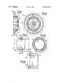
- FIG. 1is a cross-sectional view of a flywheel magneto constructed according to the method of this invention.
- FIG. 2is a cross-sectional view taken along the line II--II of FIG. 1.
- FIGS. 3 and 4are two cross-sectional views showing two manufacturing stages of the flywheel according to the invention.
- FIG. 5is a cross-sectional view taken along the line V--V of FIG. 3.
- a flywheel magneto obtained according to the method of this inventionis generally indicated at 10 and is comprised of a ring 11, made of a ferromagnetic material, in the interior of which radial magnets 12 are arranged, which are usually of a ceramic material, and their relative pole shoes 13, made of a ferromagnetic material.
- the component parts 11, 12 and 13make up a sub-assembly which is embedded in a casting 14, of a nonmagnetic alloy and equipped with a hub 15 and vanes 16 for cooling the vehicle engine, usually a motorcycle, on which said flywheel magneto finds its most typical application.
- the sub-assembly comprised of the ring 11, the magnets 12 and the pole shoes 13is prepared in the following manner.
- the ring 11is scotched onto a plurality of wedged projections 17 extended from the periphery of either base of a cylindrical mould 18.
- the magnets 12are arranged in contact with the inner surface of the ring 11, between the projections 17 which ensure that the magnets are evenly spaced apart from each other.
- the pole shoes 13are positioned along with an internal ring 19 which is made of a resilient material, generally a metallic material having an adequate plastic deformability.
- a punch 20(FIG. 4) is now forcibly introduced, the punch having an introductory bevel 21 and a ledge 22, so as to bring about a ramming and thus a radial expansion of the ring 19, such as to bring the height thereof from h 1 to h 2 (FIGS. 3 and 4).
- This operationis such as to work-harden the material of the ring 19 so as to induce a condition of elastic constriction, to which pressures against the pole shoes 13 correspond and thus thrusts between the pole shoes and the magnets 12 and also between the magnets and the ring 11, these strains being left also when the punch 20 is removed, and are sufficient for maintaining the component parts 11, 12, 13 and 19 forcibly assembled together in order to make up the sub-assembly outlined above.
Landscapes
- Engineering & Computer Science (AREA)
- Power Engineering (AREA)
- Manufacturing & Machinery (AREA)
- Permanent Field Magnets Of Synchronous Machinery (AREA)
- Manufacture Of Motors, Generators (AREA)
- Manufacturing Cores, Coils, And Magnets (AREA)
Abstract
Description
Claims (6)
Applications Claiming Priority (2)
| Application Number | Priority Date | Filing Date | Title |
|---|---|---|---|
| IT23614/80AIT1131966B (en) | 1980-07-22 | 1980-07-22 | METHOD FOR THE MANUFACTURE OF A MAGNET FLYWHEEL AND FLYWHEEL OBTAINED |
| IT23614A/80 | 1980-07-22 |
Publications (1)
| Publication Number | Publication Date |
|---|---|
| US4433473Atrue US4433473A (en) | 1984-02-28 |
Family
ID=11208585
Family Applications (1)
| Application Number | Title | Priority Date | Filing Date |
|---|---|---|---|
| US06/283,463Expired - Fee RelatedUS4433473A (en) | 1980-07-22 | 1981-07-15 | Process for manufacturing a flywheel magneto |
Country Status (11)
| Country | Link |
|---|---|
| US (1) | US4433473A (en) |
| KR (1) | KR850000730B1 (en) |
| BE (1) | BE889691A (en) |
| DE (1) | DE3126649C2 (en) |
| ES (1) | ES503325A0 (en) |
| FR (1) | FR2487598A1 (en) |
| GB (1) | GB2080707B (en) |
| IN (1) | IN156132B (en) |
| IT (1) | IT1131966B (en) |
| MX (1) | MX157642A (en) |
| NL (1) | NL8103082A (en) |
Cited By (19)
| Publication number | Priority date | Publication date | Assignee | Title |
|---|---|---|---|---|
| US4701654A (en)* | 1985-06-06 | 1987-10-20 | Nippondenso Co., Ltd. | Rotor structure of magneto generator |
| US4877986A (en)* | 1987-05-19 | 1989-10-31 | Mitsubishi Denki Kabushiki Kaisha | Rotor of magnetic generator |
| US5179872A (en)* | 1991-10-11 | 1993-01-19 | Robert J. Pernice | Magneto rotor |
| US5815907A (en)* | 1996-05-02 | 1998-10-06 | Chrysler Corporation | Method of forming a rim construction for a rotor |
| US5998902A (en)* | 1999-02-15 | 1999-12-07 | Brunswick Corporation | Magnet ring assembly for an electrical generator |
| US6242828B1 (en)* | 1999-11-18 | 2001-06-05 | Briggs & Stratton Corporation | Flywheel-rotor apparatus |
| US6339271B1 (en)* | 1999-12-21 | 2002-01-15 | Bombardier Motor Corporation Of America | Molded flywheel magnet cage |
| US6534880B1 (en)* | 1999-11-08 | 2003-03-18 | Kabushiki Kaisha Moric | Rotor of magneto generator for internal combustion engine |
| US20030146666A1 (en)* | 2001-04-27 | 2003-08-07 | Mitsubishi Denki Kabushiki Kaisha | Magneto-generator, method of manufacturing the same and resin molding die assembly for manufacturing the same |
| US7012349B1 (en)* | 2002-04-04 | 2006-03-14 | R. E. Phelon Company, Inc. | Machined rotor assembly and method of making same |
| EP1788690A1 (en)* | 2005-11-18 | 2007-05-23 | Askoll Holding S.r.l. | Method for realising a permanent magnet rotor for a synchronous motor particularly for a washing machine pump for industrial and domestic use and the like, and relative rotor |
| EP1612743A3 (en)* | 2004-06-24 | 2008-01-23 | Brady Worldwide, Inc. | Method and system for providing a document which can be visually authenticated |
| US20100077871A1 (en)* | 2008-09-29 | 2010-04-01 | Rolls-Royce Corporation | Test apparatus |
| US20110099793A1 (en)* | 2008-06-13 | 2011-05-05 | Aleksandr Pulnikov | Method for mounting a bush around a part of a shaft by means of a tight fitting |
| CN104935097A (en)* | 2014-03-17 | 2015-09-23 | 山东省明康安托山特种机电有限公司 | Forming method and structure of disc type permanent magnet motor rotor |
| US10374477B2 (en)* | 2017-03-17 | 2019-08-06 | General Electric Company | Electric machine with separable magnet carrier |
| US11156128B2 (en) | 2018-08-22 | 2021-10-26 | General Electric Company | Embedded electric machine |
| US11428160B2 (en) | 2020-12-31 | 2022-08-30 | General Electric Company | Gas turbine engine with interdigitated turbine and gear assembly |
| US12149154B2 (en) | 2021-07-22 | 2024-11-19 | General Electric Company | Electric machine having a hybrid insulative-conductive manifold |
Families Citing this family (2)
| Publication number | Priority date | Publication date | Assignee | Title |
|---|---|---|---|---|
| JP4312778B2 (en) | 2006-08-09 | 2009-08-12 | 三菱電機株式会社 | Magnet generator manufacturing method |
| ITMI20110374A1 (en)* | 2011-03-10 | 2012-09-11 | Wilic Sarl | WIND TURBINE |
Citations (4)
| Publication number | Priority date | Publication date | Assignee | Title |
|---|---|---|---|---|
| US3258623A (en) | 1963-05-02 | 1966-06-28 | Phelon Co Inc | Rotor for an electric generator |
| US3818586A (en) | 1971-09-16 | 1974-06-25 | Briggs & Stratton Corp | Method of making an assembly of alternator magnet blocks with engine flywheel |
| US3861028A (en) | 1972-11-11 | 1975-01-21 | Bosch Gmbh Robert | Method of producing a magneto rotor |
| US4182027A (en) | 1977-03-29 | 1980-01-08 | Novi-P.B. | Method of assembling a magneto rotor assembly |
Family Cites Families (7)
| Publication number | Priority date | Publication date | Assignee | Title |
|---|---|---|---|---|
| DE1072720B (en)* | 1960-01-07 | Deutsche Edelstahlwerke Aktiengesellschaft, Krefeld | Annular permanent magnet arrangement for pilot light flywheels | |
| US3008062A (en)* | 1957-12-12 | 1961-11-07 | Tkm Electric Corp | Dynamoelectric machine |
| US3132270A (en)* | 1959-09-29 | 1964-05-05 | Phelon Co Inc | Rotor annulus for electric generator |
| US3657582A (en)* | 1969-05-13 | 1972-04-18 | Russell E Phelon | Rotor annulus for electric generator |
| US3828212A (en)* | 1971-09-16 | 1974-08-06 | Briggs & Stratton Corp | Assembly of alternator magnet blocks with engine flywheel |
| US3810056A (en)* | 1972-08-28 | 1974-05-07 | Outboard Marine Corp | Non-magnetized ceramic magnetic assembly |
| JPS5840422B2 (en)* | 1975-07-25 | 1983-09-06 | 株式会社日立製作所 | magnet generator rotor |
- 1980
- 1980-07-22ITIT23614/80Apatent/IT1131966B/enactive
- 1981
- 1981-06-15ININ381/DEL/81Apatent/IN156132B/enunknown
- 1981-06-23ESES503325Apatent/ES503325A0/enactiveGranted
- 1981-06-25NLNL8103082Apatent/NL8103082A/ennot_activeApplication Discontinuation
- 1981-07-03GBGB8120619Apatent/GB2080707B/ennot_activeExpired
- 1981-07-07DEDE3126649Apatent/DE3126649C2/ennot_activeExpired
- 1981-07-11KRKR1019810002518Apatent/KR850000730B1/ennot_activeExpired
- 1981-07-15USUS06/283,463patent/US4433473A/ennot_activeExpired - Fee Related
- 1981-07-17FRFR8113974Apatent/FR2487598A1/enactiveGranted
- 1981-07-21MXMX188397Apatent/MX157642A/enunknown
- 1981-07-22BEBE0/205457Apatent/BE889691A/ennot_activeIP Right Cessation
Patent Citations (4)
| Publication number | Priority date | Publication date | Assignee | Title |
|---|---|---|---|---|
| US3258623A (en) | 1963-05-02 | 1966-06-28 | Phelon Co Inc | Rotor for an electric generator |
| US3818586A (en) | 1971-09-16 | 1974-06-25 | Briggs & Stratton Corp | Method of making an assembly of alternator magnet blocks with engine flywheel |
| US3861028A (en) | 1972-11-11 | 1975-01-21 | Bosch Gmbh Robert | Method of producing a magneto rotor |
| US4182027A (en) | 1977-03-29 | 1980-01-08 | Novi-P.B. | Method of assembling a magneto rotor assembly |
Cited By (28)
| Publication number | Priority date | Publication date | Assignee | Title |
|---|---|---|---|---|
| US4701654A (en)* | 1985-06-06 | 1987-10-20 | Nippondenso Co., Ltd. | Rotor structure of magneto generator |
| US4877986A (en)* | 1987-05-19 | 1989-10-31 | Mitsubishi Denki Kabushiki Kaisha | Rotor of magnetic generator |
| US5179872A (en)* | 1991-10-11 | 1993-01-19 | Robert J. Pernice | Magneto rotor |
| US5815907A (en)* | 1996-05-02 | 1998-10-06 | Chrysler Corporation | Method of forming a rim construction for a rotor |
| US5998902A (en)* | 1999-02-15 | 1999-12-07 | Brunswick Corporation | Magnet ring assembly for an electrical generator |
| US6534880B1 (en)* | 1999-11-08 | 2003-03-18 | Kabushiki Kaisha Moric | Rotor of magneto generator for internal combustion engine |
| US6242828B1 (en)* | 1999-11-18 | 2001-06-05 | Briggs & Stratton Corporation | Flywheel-rotor apparatus |
| US6339271B1 (en)* | 1999-12-21 | 2002-01-15 | Bombardier Motor Corporation Of America | Molded flywheel magnet cage |
| US6548925B2 (en) | 1999-12-21 | 2003-04-15 | Bombardier Motor Corporation Of America | Molded flywheel magnet cage |
| US20030146666A1 (en)* | 2001-04-27 | 2003-08-07 | Mitsubishi Denki Kabushiki Kaisha | Magneto-generator, method of manufacturing the same and resin molding die assembly for manufacturing the same |
| US7178219B2 (en)* | 2001-04-27 | 2007-02-20 | Mitsubishi Denki Kabushiki Kaisha | Method of manufacturing a magneto-generator |
| US7012349B1 (en)* | 2002-04-04 | 2006-03-14 | R. E. Phelon Company, Inc. | Machined rotor assembly and method of making same |
| EP1612743A3 (en)* | 2004-06-24 | 2008-01-23 | Brady Worldwide, Inc. | Method and system for providing a document which can be visually authenticated |
| US20070114867A1 (en)* | 2005-11-18 | 2007-05-24 | Askoll Holding S.R.L. | Method for realising a permanent-magnet rotor for a synchronous motor particularly for a washing machine pump for industrial and domestic use and the like, and relative rotor |
| EP1788690A1 (en)* | 2005-11-18 | 2007-05-23 | Askoll Holding S.r.l. | Method for realising a permanent magnet rotor for a synchronous motor particularly for a washing machine pump for industrial and domestic use and the like, and relative rotor |
| US20080307635A1 (en)* | 2005-11-18 | 2008-12-18 | Askoll Holding S.R.L. | Method for realising a permanent-magnet rotor for a synchronous motor particularly for a washing machine pump for industrial and domestic use and the like, and relative rotor |
| US7612478B2 (en) | 2005-11-18 | 2009-11-03 | Askoll Holding S.R.L. | Permanent-magnet rotor for a synchronous motor particularly for a washing machine pump for industrial and domestic use and the like |
| US8146234B2 (en) | 2005-11-18 | 2012-04-03 | Askoll Holding S.R.L. | Method for realising a permanent-magnet rotor for a synchronous motor |
| US20110099793A1 (en)* | 2008-06-13 | 2011-05-05 | Aleksandr Pulnikov | Method for mounting a bush around a part of a shaft by means of a tight fitting |
| US8769797B2 (en)* | 2008-06-13 | 2014-07-08 | Atlas Copco Airpower, Naamloze Vennootschap | Method for mounting a bush around a part of a shaft by means of a tight fitting |
| US9332825B2 (en) | 2008-06-13 | 2016-05-10 | Atlas Copco Airpower, Naamloze Vennootschap | Method for mounting a bush around a part of a shaft by means of a tight fitting |
| US7908929B2 (en)* | 2008-09-29 | 2011-03-22 | Rolls-Royce Corporation | Test apparatus |
| US20100077871A1 (en)* | 2008-09-29 | 2010-04-01 | Rolls-Royce Corporation | Test apparatus |
| CN104935097A (en)* | 2014-03-17 | 2015-09-23 | 山东省明康安托山特种机电有限公司 | Forming method and structure of disc type permanent magnet motor rotor |
| US10374477B2 (en)* | 2017-03-17 | 2019-08-06 | General Electric Company | Electric machine with separable magnet carrier |
| US11156128B2 (en) | 2018-08-22 | 2021-10-26 | General Electric Company | Embedded electric machine |
| US11428160B2 (en) | 2020-12-31 | 2022-08-30 | General Electric Company | Gas turbine engine with interdigitated turbine and gear assembly |
| US12149154B2 (en) | 2021-07-22 | 2024-11-19 | General Electric Company | Electric machine having a hybrid insulative-conductive manifold |
Also Published As
| Publication number | Publication date |
|---|---|
| DE3126649A1 (en) | 1982-05-27 |
| KR850000730B1 (en) | 1985-05-23 |
| MX157642A (en) | 1988-12-08 |
| NL8103082A (en) | 1982-02-16 |
| ES8204247A1 (en) | 1982-04-16 |
| GB2080707A (en) | 1982-02-10 |
| IT8023614A0 (en) | 1980-07-22 |
| KR830006975A (en) | 1983-10-12 |
| GB2080707B (en) | 1983-10-12 |
| FR2487598A1 (en) | 1982-01-29 |
| IT1131966B (en) | 1986-06-25 |
| FR2487598B1 (en) | 1984-11-23 |
| BE889691A (en) | 1981-11-16 |
| ES503325A0 (en) | 1982-04-16 |
| IN156132B (en) | 1985-05-18 |
| DE3126649C2 (en) | 1985-02-14 |
Similar Documents
| Publication | Publication Date | Title |
|---|---|---|
| US4433473A (en) | Process for manufacturing a flywheel magneto | |
| EP0633648B1 (en) | Permanent-magnet rotor for electric motors and process of manufacturing the same | |
| US4918802A (en) | Method and apparatus for making permanent magnet rotors | |
| US2048161A (en) | Dynamo-electric machine frame | |
| JP2806570B2 (en) | Method of manufacturing a salient pole of a motor and a motor element | |
| US4625392A (en) | Method of manufacturing a molded rotatable assembly for dynamoelectric machines | |
| EP1354653A1 (en) | Sinterbonded electric machine components | |
| US3861028A (en) | Method of producing a magneto rotor | |
| US3368275A (en) | Casting, machining, and assembling a magnetic motor ring structure | |
| US6900573B2 (en) | Rotor core lamination for a laminated rotor | |
| US3390291A (en) | Permanent magnet rotor structure for a dynamoelectric machine | |
| JPH0813174B2 (en) | Rotor of rotating machine with permanent magnet | |
| JPH0739117A (en) | Method for assembling permanent magnet type rotor magnet with cylindrical cover | |
| JPH1014147A (en) | Rotating machine having circumferentially magnetized rotor and method of manufacturing the same | |
| US4340560A (en) | Method for making a rotor assembly | |
| JP2569221B2 (en) | Motor manufacturing method | |
| JPH027264B2 (en) | ||
| JP2003299275A (en) | Rotor and molding die for rotor | |
| JP2004140978A (en) | Squirrel cage induction rotor, and its manufacturing method | |
| GB1377910A (en) | Method of fabricating magnetmotive devices | |
| US3885177A (en) | Pole-shoe magnet group for a magnetomotive device | |
| JP2526144Y2 (en) | Permanent magnet rotor | |
| JP2527656Y2 (en) | Permanent magnet rotor | |
| JP2723659B2 (en) | Method for manufacturing rotor of small motor | |
| JPH0727261U (en) | Resin motor case |
Legal Events
| Date | Code | Title | Description |
|---|---|---|---|
| AS | Assignment | Owner name:PIAGGIO & C. S.P.A., GENOVA (ITALY) Free format text:ASSIGNMENT OF ASSIGNORS INTEREST.;ASSIGNOR:BENEDETTI, CARLO;REEL/FRAME:003901/0032 Effective date:19810616 | |
| FEPP | Fee payment procedure | Free format text:PAYOR NUMBER ASSIGNED (ORIGINAL EVENT CODE: ASPN); ENTITY STATUS OF PATENT OWNER: LARGE ENTITY | |
| MAFP | Maintenance fee payment | Free format text:PAYMENT OF MAINTENANCE FEE, 4TH YEAR, PL 96-517 (ORIGINAL EVENT CODE: M170); ENTITY STATUS OF PATENT OWNER: LARGE ENTITY Year of fee payment:4 | |
| AS | Assignment | Owner name:PIAGGIO VEICOLI EUROPEI S.R.L., A COMPANY OF ITALY Free format text:ASSIGNMENT OF ASSIGNORS INTEREST.;ASSIGNOR:PIAGGIO + C. S.P.A.;REEL/FRAME:005623/0050 Effective date:19890731 Owner name:PIAGGIO VEICOLI EUROPEI S.P.A., ITALY Free format text:CHANGE OF NAME;ASSIGNOR:PIAGGIO VERICOLI EUROPEI S.R.L.;REEL/FRAME:005623/0071 Effective date:19901015 | |
| FEPP | Fee payment procedure | Free format text:MAINTENANCE FEE REMINDER MAILED (ORIGINAL EVENT CODE: REM.); ENTITY STATUS OF PATENT OWNER: LARGE ENTITY | |
| LAPS | Lapse for failure to pay maintenance fees | ||
| FP | Lapsed due to failure to pay maintenance fee | Effective date:19920301 | |
| STCH | Information on status: patent discontinuation | Free format text:PATENT EXPIRED DUE TO NONPAYMENT OF MAINTENANCE FEES UNDER 37 CFR 1.362 |