US4432005A - Ink control system for ink jet printer - Google Patents
Ink control system for ink jet printerDownload PDFInfo
- Publication number
- US4432005A US4432005AUS06/376,758US37675882AUS4432005AUS 4432005 AUS4432005 AUS 4432005AUS 37675882 AUS37675882 AUS 37675882AUS 4432005 AUS4432005 AUS 4432005A
- Authority
- US
- United States
- Prior art keywords
- ink
- reservoir
- reservoirs
- primary
- chamber
- Prior art date
- Legal status (The legal status is an assumption and is not a legal conclusion. Google has not performed a legal analysis and makes no representation as to the accuracy of the status listed.)
- Expired - Fee Related
Links
- 238000013022ventingMethods0.000claims2
- 238000010926purgeMethods0.000abstractdescription14
- 229920002457flexible plasticPolymers0.000abstractdescription8
- 230000003287optical effectEffects0.000abstractdescription3
- 239000002985plastic filmSubstances0.000abstractdescription2
- 239000000976inkSubstances0.000description145
- 239000002699waste materialSubstances0.000description14
- 229920003023plasticPolymers0.000description8
- 239000004033plasticSubstances0.000description8
- 238000004519manufacturing processMethods0.000description5
- 239000003086colorantSubstances0.000description4
- 238000011010flushing procedureMethods0.000description4
- 230000008859changeEffects0.000description2
- 238000010276constructionMethods0.000description2
- 230000002706hydrostatic effectEffects0.000description2
- 238000009434installationMethods0.000description2
- 230000007246mechanismEffects0.000description2
- 238000000034methodMethods0.000description2
- 238000005192partitionMethods0.000description2
- 238000007789sealingMethods0.000description2
- 239000004698PolyethyleneSubstances0.000description1
- 230000002745absorbentEffects0.000description1
- 239000002250absorbentSubstances0.000description1
- 238000010521absorption reactionMethods0.000description1
- 230000004913activationEffects0.000description1
- 230000002411adverseEffects0.000description1
- 238000011109contaminationMethods0.000description1
- 238000001514detection methodMethods0.000description1
- 238000007429general methodMethods0.000description1
- 230000005484gravityEffects0.000description1
- 239000012535impuritySubstances0.000description1
- 230000002452interceptive effectEffects0.000description1
- 239000007788liquidSubstances0.000description1
- 239000000463materialSubstances0.000description1
- 238000012986modificationMethods0.000description1
- 230000004048modificationEffects0.000description1
- 238000012806monitoring deviceMethods0.000description1
- 238000012544monitoring processMethods0.000description1
- 238000012354overpressurizationMethods0.000description1
- 239000002245particleSubstances0.000description1
- 230000000149penetrating effectEffects0.000description1
- 229920006255plastic filmPolymers0.000description1
- -1polyethylenePolymers0.000description1
- 229920000573polyethylenePolymers0.000description1
- 230000037452primingEffects0.000description1
- 230000004044responseEffects0.000description1
- 239000002904solventSubstances0.000description1
- 238000012546transferMethods0.000description1
- 238000003466weldingMethods0.000description1
Images


Classifications
- B—PERFORMING OPERATIONS; TRANSPORTING
- B41—PRINTING; LINING MACHINES; TYPEWRITERS; STAMPS
- B41J—TYPEWRITERS; SELECTIVE PRINTING MECHANISMS, i.e. MECHANISMS PRINTING OTHERWISE THAN FROM A FORME; CORRECTION OF TYPOGRAPHICAL ERRORS
- B41J2/00—Typewriters or selective printing mechanisms characterised by the printing or marking process for which they are designed
- B41J2/005—Typewriters or selective printing mechanisms characterised by the printing or marking process for which they are designed characterised by bringing liquid or particles selectively into contact with a printing material
- B41J2/01—Ink jet
- B41J2/17—Ink jet characterised by ink handling
- B41J2/175—Ink supply systems ; Circuit parts therefor
- B41J2/17566—Ink level or ink residue control
- B41J2002/17573—Ink level or ink residue control using optical means for ink level indication
Definitions
- This inventionrelates to ink jet printers of the type in which ink is ejected in droplets from a moving head to form a desired pattern. More particularly this invention relates to an improved ink supply system for a multi-color ink jet printer.
- a manually operable system for purgingmust be provided to remove any air bubbles or contamination from the ink passages or orifices.
- an ink jetmust normally be primed with clean bubble-free ink. Because the orifices are small, even tiny bits of foreign matter can plug the orifice or an ink passageway or otherwise interfere with proper operation.
- an impulse ink jet systembecause ink droplet ejection results from the application of a pressure pulse to the ink, air bubbles adversely affect operation by the absorption of part of the pressure pulse and interfering with the proper ejection of a droplet. Even after initial priming, an impulse ink jet may draw in an air bubble through the orifice and require purging before satisfactory operation can be resumed.
- U.S. Pat. No. 4,123,761 to Kimura et al.shows a single-color system in which a reserve ink supply is maintained under pressure and when a purge valve is opened the ink is forced through the passages to remove any bubbles and impurities. A suction system is operated during the purging operation to remove waste ink and return it to a chamber surrounding the ink supply reservoir
- U.S. Pat. No. 4,038,667 to Hou et al.shows a somewhat similar purging system in which a separate ink reservoir is maintained under pressure for the sole purpose of purging the ink channels.
- the volume of ink in the movable reservoirmust be limited so that the total mass of the moving assembly is maintained within a tolerable limit.
- the carriage mounted reservoirmust maintain a reasonably constant hydrostatic pressure at the printing orifices, for example, between 1 and 3 centimeters below atmospheric. This limitation requires that the ink reservoir be relatively shallow and the resulting lateral dimensions limit the capacity of the reservoir that can be carried.
- Other requirementsinclude a jet feed system capable of delivering ink, with a viscosity of 20 centipoise, at a rate of at least 0.5 cubic centimeters per minute, for each color, without significant viscous pressure loss.
- the ink in the systemmust at all times be prevented from contact with the air. It is highly desirable that the ink be provided in a low-cost easily replaceable cartridge with an automatic signal to indicate when the ink supply is low.
- One method of purging an ink jet printerfor example, of the type described in U.S. Pat. No. 4,126,868 to Kirner, is to apply pressure to the flexible cap of the ink reservoir to force a flow of ink through the passages and orifice.
- an ink reservoir of larger areahowever, the force required to achieve purging by this method becomes excessive.
- Such a reservoiris usually made by sealing a flexible diaphragm or cap around its periphery to the edge of a tub-shaped base. This sealing operation becomes more difficult in production with large capacities and is particularly difficult, with the likelihood of leaks, if the reservoirs are relatively long and slender.
- the reservoiris in the form of a tubular sack formed entirely of a thin plastic film
- new problemsarise.
- the sackmust be very flexible so that it collapses readily as the ink is withdrawn. If the plastic is too stiff, the ink is not withdrawn and air is drawn into the system through the jet orifices. The combination of the requisite strength and easy collapsibility is difficult to achieve. The problem is compounded by cost factors because, for purposes of convenience, the ink cartridge must be disposable and therefore modest in cost.
- U.S. Pat. No. 4,202,267 to Heinzl et al.describes an ink reservoir having a rigid base covered by a collapsible rubber dome in which a monitoring device that detects the absence of ink in the container by monitoring the resistance of the ink.
- a monitoring devicethat detects the absence of ink in the container by monitoring the resistance of the ink.
- Such a systemis affected, however, by changes in the resistance of the ink, whether by reason of changes in temperature, viscosity, composition or other factor, and a three-electrode bridge measuring system, such as that described by Kern in U.S. Pat. No. 4,196,625, is much to be preferred.
- the latter systemdoes, however, require three electrodes in the ink reservoir. For a three-color ink system, nine electrodes would be required.
- U.S. Pat. No. 4,178,595 to Jinnai et al.describes an ink supply system in which a primary ink reservoir feeds a smaller reservoir carried by the moving head. At the end of a printing line, a sensor determines whether the ink supply in the small reservoir is low. If ink is needed, the printing head is moved to bring the smaller ink reservoir into mechanical engagement with the larger reservoir so that the smaller reservoir is replenished. The ink supply in the smaller reservoir is again sensed and if found to be low, a signal is provided to indicate the larger reservoir is empty.
- U.S. Pat. No. 4,183,031 to Kyser et al.uses a pressure-responsive sensor to detect when the ink supply is low. Still other arrangements of ink supply systems are shown in U.S. Pat. Nos. 4,204,215 to Nakara; 4,184,167 to Vandervalk; 4,126,868 to Kirner; and 4,149,172 to Heinzl.
- the inventionis embodied in a pressurized ink supply system for a three color ink jet printer.
- three stationary primary ink reservoirsare connected by flexible plastic umbilical tubes to three secondary ink reservoirs mounted on the carriage and move with the print head across the sheet being printed.
- the three primary reservoirscomprise relatively long tubular sacks of flexible plastic housed in a closed container that is kept under continuous pressure. If the ink level were to be measured by the change in resistance using the general method described by Kern in U.S. Pat. No. 4,196,625 it would be necessary to provide for three electrodes within the ink reservoir. This is best accomplished by providing a rigid plastic trough as the bottom portion of each reservoir and to weld a flexible collapsible cap to the periphery of the trough. The three electrodes can then be formed integrally with the rigid bottom. However, the welding of the flexible plastic to such a long base is difficult and unreliable in production quantities. A lower cost and more practical solution is to form the primary reservoirs entirely of flexible plastic.
- the ink level in each secondary reservoiris maintained within close limits without attention from the operator.
- an alarmalerts the operator to remove and replace the ink cartridge.
- the pressure in the primary reservoirsis utilized for carrying the ink to the secondary reservoirs under automatic control, and under manual control for purging the ink passages by momentarily opening the passageways between the primary reservoirs and the secondary reservoirs for a period sufficient to allow the pressure in the secondary reservoirs to equal the pressure in the primary reservoirs and force the ink through the orifices.
- the waste ink that is discharged by this purging operationis captured and returned to a separate compartment in a disposable cartridge that houses the three primary ink reservoirs. This waste receiving chamber is maintained under a slight vacuum by the same pump that provides the pressure for the ink reservoirs.
- Each secondary reservoiris provided with a rigid tub-like bottom covered by a thin flexible dome.
- the flexible domescollapse.
- the domesare allowed to collapse only a certain predetermined distance before a position sensing device, such as an optical sensor located above each of the flexible domes, activates an automatic mechanism to allow ink to flow from the primary reservoir into the secondary.
- the flow of inkis stopped before the flexible dome is fully expanded to prevent over-pressurization of the secondary reservoir.
- the distance traveled by the top of the dome in each fill cycleis determined by the hysteresis of the position detector and the automatic valve.
- This same level detection system in the secondary reservoircan also be used to sense an ink-out condition in the primary reservoir and thus avoid the difficult problem of penetrating each of the three ink sacks with three electrode needles.
- a timeris activated. If the sensor has not been satisfied within a predetermined time interval, an ink-out condition is activated and the operator is alerted that the primary ink cartridge must be replaced.
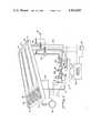
- FIG. 1is a diagrammatic illustration showing the principal components of the ink supply system embodying the invention
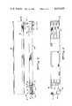
- FIG. 2is a side view of the primary reservoir showing the principal components prior to assembly
- FIG. 3is a top view of the primary ink reservoir with portions of the cover cut away;
- FIG. 4shows one of the hollow sharpened needles by which connection is made to the disposable primary ink cartridge
- FIG. 5is an enlarged vertical sectional view of the secondary ink reservoir
- FIG. 6is a top view of the lower part of the secondary ink reservoir
- FIG. 7is an end view of the reservoir shown in FIG. 6;
- FIG. 8is a top view of the flexible diaphragm of the secondary ink reservoir.
- FIG. 9is a side view of the diaphragm shown in FIG. 8.
- FIG. 10is a bottom view of the cap of the secondary ink reservoir
- FIG. 11is a section along line 11--11 of FIG. 10;
- FIG. 12is a section along line 12--12 of FIG. 10;
- FIG. 13is a bottom view of the printed circuit board mounting for the ink sensors.
- FIG. 14is a side view of the board shown in FIG. 13.
- a movable carriage assemblysupports a printing head 4 having multiple ink jet orifices (not shown) that are connected by ink supply tubes, indicated diagrammatically at 6, to three secondary ink reservoirs 8a, 8b, and 8c for the three colors of ink.
- the secondary ink reservoir 8ais connected by a flexible plastic umbilical tube 12a to a supply reservoir comprising a flexible ink sack 14a positioned in a compartment 16 of a rigid plastic housing 18 that forms a replaceable ink cartridge.
- the compartment 16is maintained under constant pressure, for example between 3 and 7 pounds per square inch, by an air pump 22.
- the pumpis conventional and of a type readily available commercially.
- the compartment 16also contains two additional containers 14b and 14c for the other colors of ink.
- the ink from each of the three secondary reservoirsis fed to the orifices under impulses generated by piezoelectric means in the usual manner that is well known in the art.
- the secondary reservoirsare small in size so that minimum mass is required to be carried by the moving carriage assembly 2. It is important that the level of ink in the secondary reservoirs be maintained within relatively close limits so that the hydrostatic pressure at the orifices is within practical operating limits, for example, between 1 and 3 centimeters below atmospheric, with no substantial disparity between the three colors of ink.
- a sensor unitgenerally indicated at 24a, 24b and 24c, is incorporated in each of the secondary reservoirs and when the ink in any secondary reservoir drops below a predetermined level, an appropriate solenoid-operated valve of those indicated generally at 26a, 26b and 26c is opened and allows ink to flow through the valve into the secondary reservoir until the level sensor indicates the reservoir has been filled to the desired height.
- Actuation of the solenoid valve 26aalso starts a timer circuit in a central processor unit, indicated diagrammatically at 28. If the sensor 24a fails to indicate within some predetermined period of time that the reservoir 8a has been filled, a signal light 32 is lit to indicate to the operator that the ink in the primary sack 14a is low and the disposable ink cartridge 18 is to be replaced. This filling operation occurs only at the end of a line, when the printing head is inactive, and requires only a fraction of a second to transfer the required amount of ink.
- the control circuits 28include software that prevents activation of the solenoid valves 26a, 26b and 26c when the printing head is moving.
- a manual switch 36is provided that simultaneously energizes each of the solenoid valves 26a, 26b and 26c and permits the flow of ink into the three secondary reservoirs 8a, 8b, and 8c so that these reservoirs assume the same pressure as the primary chamber 16 forcing ink from the secondary reservoirs and flushing the ink passages and the orifices.
- a separate sealed chamber 38is provided in the cartridge 18 and is connected by a flexible tube 42 to the input side of the air pump 22.
- Another such tube 44connects the chamber 38 to a conventional collection trough (not shown) that receives the waste ink from the printing head 4.
- the pump 22maintains a slight suction in the chamber 38 so that waste ink is sucked into the chamber 38.
- a wick 46 of absorbent materialmay be placed in the chamber 38 to absorb the waste ink. The waste ink is thus disposed of each time the cartridge 18 is replaced.
- FIG. 1the electrical connections are illustrated diagrammatically by broken lines. Details of the electrical circuits are not shown here since the necessary circuitry will be apparent to those skilled in the art.
- a bottom tray 48has two dividers 52 and 54, terminated at one end by a partition 56, that form three longitudinal compartments within the chamber 16.
- the construction of the ink sack 14c shown in FIG. 2is typical of each of the three sacks.
- the sackmay be formed of two strips of thin flexible plastic heat sealed along the edges.
- the sack 14cmay, for example, be approximately 15 inches in length and of such cross section as to provide a capacity for about 100 cubic centimeters of ink.
- a rigid plastic collar 58Near one end of the sack, a rigid plastic collar 58 is sealed to the outer surface of one wall of the sack.
- a soft rubber plug 62is press-fitted into the collar 58 and forms an ink-tight seal.
- the ink sackis filled, for example, with ink at the opposite end from the collar 58 before that end of the sack is sealed.
- the sack filled with inkis then placed in one of the longitudinal cavities of the chamber 16 with the collar 58 extending into a well 64 formed on the underside of the tray 48.
- the well 64is sealed at its lower end by a plastic cap 66.
- an opening 67is provided in the floor of the tray 48. This opening is sealed until the time of installation.
- a flanged cover 68is secured to the top of the tray and sealed tightly around its periphery and along the top edge of the partition 56 so that the chamber 16 is completely sealed from the outside air and from the waste ink in the chamber 38.
- the cartridge 18may thus be shipped and handled without danger of ink spillage even if one of the ink sacks should be ruptured.
- the chamber 38which is also completely sealed by the cover 68, contains a standpipe 72 that is connected through an opening in the bottom of the tray to the suction tubing 42.
- a plastic abutment 74formed integrally with the tray 48, has a vertical bore 76 that is arranged for connection, by any suitable means, to the waste ink tube 44. The waste ink enters the compartment 38 through the bore 76 and runs down a sloping face 78 to be absorbed by the wick 46 which may substantially fill the chamber 38.
- the ink cartridge 18When the ink cartridge 18 is to be installed in the printer, it is placed on a receiving structure (not shown) and forced downwardly into position.
- a receiving structure(not shown) and forced downwardly into position.
- three hollow sharpened needlesare mounted in a base 82 that forms a rigid part of the receiving structure.
- the lower end of each hollow needle 78is connected to the appropriate ink supply tube 12a, 12b or 12c.
- the sharpened end of each needlepenetrates, in succession, the cap 66, the rubber plug 62 and the wall of the corresponding ink sack 14a, 14b, or 14c. Connections are then made, by any suitable means (not shown), to the flexible tubes 23, 42 and 44.
- the cartridgeis now completely connected and provides a source of a substantial quantity of each of the three colors of ink.
- FIGS. 5-14show details of the secondary reservoir cartridge 10.
- a base 84comprises a plastic block containing bottom cavity sections of the three secondary reservoirs 8a, 8b and 8c (FIGS. 6 and 7).
- Three holes 86a, 86b and 86cextend laterally from the lowest points of the rounded bottoms of the reservoirs for connection to the appropriate orifices in the printing head 4.
- a thin flexible diaphragm 88Positioned directly on top of the base 84 is a thin flexible diaphragm 88 (FIGS. 8 and 9) formed, for example, from one mil opaque polyethylene and having three domes 92a, 92b and 92c.
- a cover 94(FIGS. 10-12), positioned directly on top of the diaphragm 88, is formed from a rigid block of plastic and contains three dome sections 96a, 96b and 96c dimensioned to receive the diaphragm domes 92a, 92b and 92c.
- the cover 94has three small vent holes 98a, 98b and 98c extending from the dome cavity to the top of the cover.
- each cover dome cavityOn opposite sides of each cover dome cavity there is a vertical hole 102 that extends from the top of the cover part way through and opens into the dome in the area of its maximum diameter. These openings are provided to receive the optical illuminators 104 (FIGS. 13 and 14). A similar hole 106 on the opposite side of each dome 96 receives the corresponding sensor 108.
- a printed circuit board 110serves as a mounting for the three infrared illuminators 104 and the three sensors 108.
- the connector terminals 112are appropriately connected to the sensors and illuminators by printed circuit leads (not shown) and are in turn connected to the appropriate control circuits.
- Each of the illuminators 104is positioned in one of the openings 102 and in line with one of the sensors 108 positioned in the opposite hole 106.
- each of the diaphragm domes 92a, 92b and 92cis forced upwardly into the corresponding dome section 96a, 96b or 96c. Free movement of the diaphragms into and from the cover is assured by the three vent holes 98a, 98b and 98c.
- the diaphragm 88which may be opaque, is forced upwardly into the cover 94, either the diaphragm 88 or the colored ink interrupts the infrared beam between each illuminator and its corresponding sensor.
Landscapes
- Ink Jet (AREA)
Abstract
Description
Claims (2)
Priority Applications (1)
| Application Number | Priority Date | Filing Date | Title |
|---|---|---|---|
| US06/376,758US4432005A (en) | 1982-05-10 | 1982-05-10 | Ink control system for ink jet printer |
Applications Claiming Priority (1)
| Application Number | Priority Date | Filing Date | Title |
|---|---|---|---|
| US06/376,758US4432005A (en) | 1982-05-10 | 1982-05-10 | Ink control system for ink jet printer |
Publications (1)
| Publication Number | Publication Date |
|---|---|
| US4432005Atrue US4432005A (en) | 1984-02-14 |
Family
ID=23486356
Family Applications (1)
| Application Number | Title | Priority Date | Filing Date |
|---|---|---|---|
| US06/376,758Expired - Fee RelatedUS4432005A (en) | 1982-05-10 | 1982-05-10 | Ink control system for ink jet printer |
Country Status (1)
| Country | Link |
|---|---|
| US (1) | US4432005A (en) |
Cited By (107)
| Publication number | Priority date | Publication date | Assignee | Title |
|---|---|---|---|---|
| US4539569A (en)* | 1982-10-26 | 1985-09-03 | Canon Kabushiki Kaisha | Ink jet recording apparatus |
| US4549189A (en)* | 1982-06-04 | 1985-10-22 | Fuji Xerox Co., Ltd. | Thermal printing head |
| US4551734A (en)* | 1984-12-06 | 1985-11-05 | Tektronix, Inc. | Ink cartridge with ink level sensor |
| US4628334A (en)* | 1984-02-15 | 1986-12-09 | Ing. C. Olivetti & C., S.P.A. | Ink jet print head cartridge assembly |
| US4631558A (en)* | 1982-05-06 | 1986-12-23 | Sharp Kabushiki Kaisha | Ink liquid baffle-regulated reservoir in an ink jet system printer |
| US4636814A (en)* | 1983-08-02 | 1987-01-13 | Canon Kabushiki Kaisha | Printing apparatus |
| FR2585289A1 (en)* | 1985-07-24 | 1987-01-30 | Canon Kk | INKJET RECORDING APPARATUS AND INK FEEDING DEVICE |
| US4819012A (en)* | 1983-06-10 | 1989-04-04 | Canon Kabushiki Kaisha | Ink-jet printer with cap means |
| US4870431A (en)* | 1987-11-02 | 1989-09-26 | Howtek, Inc. | Ink jet priming system |
| US4878069A (en)* | 1984-07-09 | 1989-10-31 | Canon Kabushiki Kaisha | Ink jet recording apparatus with an ink tank-carriage configuration for increasing useable space |
| US4977413A (en)* | 1987-04-15 | 1990-12-11 | Canon Kabushiki Kaisha | Ink remain detector having a flexible member and a liquid injection recording apparatus utilizing the detector |
| US5136309A (en)* | 1986-03-19 | 1992-08-04 | Canon Kabushiki Kaisha | Liquid injection apparatus with residual ink quantity detecting means |
| US5136305A (en)* | 1990-12-06 | 1992-08-04 | Xerox Corporation | Ink jet printer with ink supply monitoring means |
| US5367328A (en)* | 1993-10-20 | 1994-11-22 | Lasermaster Corporation | Automatic ink refill system for disposable ink jet cartridges |
| US5400066A (en)* | 1990-12-10 | 1995-03-21 | Canon Kabushiki Kaisha | Ink tank cartridge that prevents leakage of residual ink and ink jet recording apparatus using same |
| DE4425693A1 (en)* | 1993-10-20 | 1995-04-27 | Lasermaster Corp | Automatic ink refill system for disposable inkjet cartridges |
| US5473350A (en)* | 1992-08-06 | 1995-12-05 | Scitex Digital Printing, Inc. | System and method for maintaining ink concentration in a system |
| WO1996014989A3 (en)* | 1994-11-10 | 1996-10-31 | Lasermaster Corp | Large format ink jet printer and ink supply system |
| US5616929A (en)* | 1994-02-07 | 1997-04-01 | Fuji Xerox Co., Ltd. | Ink tank with an ink level detector having a viewing window |
| US5623290A (en)* | 1986-03-19 | 1997-04-22 | Canon Kabushiki Kaisha | Recording apparatus and supply system having residual ink quantity detection |
| EP0666178A3 (en)* | 1994-02-04 | 1997-08-20 | Hewlett Packard Co | Ink delivery system for a printer. |
| US5691755A (en)* | 1994-04-18 | 1997-11-25 | Hewlett-Packard Company | Collapsible ink cartridge |
| US5729256A (en)* | 1987-04-15 | 1998-03-17 | Canon Kabushiki Kaisha | Ink remain detector having a biased flexible film member with limited deformation |
| US5797074A (en)* | 1995-04-14 | 1998-08-18 | Ricoh Company, Ltd. | Image forming system |
| US5870124A (en)* | 1995-04-12 | 1999-02-09 | Eastman Kodak Company | Pressurizable liquid ink cartridge for coincident forces printers |
| US5877795A (en)* | 1996-05-24 | 1999-03-02 | Hewlett-Packard Co. | Methods and designs to purge air from ink tubes during initial startup |
| US5880748A (en)* | 1994-09-20 | 1999-03-09 | Hewlett-Packard Company | Ink delivery system for an inkjet pen having an automatic pressure regulation system |
| WO1999011933A1 (en)* | 1997-08-29 | 1999-03-11 | Topaz Technologies, Inc. | Multi-channel ink supply pump |
| US5900888A (en)* | 1995-06-19 | 1999-05-04 | Canon Kabushiki Kaisha | Printing apparatus and facsimile apparatus using same |
| US5949459A (en)* | 1997-06-04 | 1999-09-07 | Hewlett-Packard Company | Method and apparatus for securing an ink container |
| EP0953450A1 (en)* | 1998-04-30 | 1999-11-03 | Hewlett-Packard Company | Inkjet ink level detection |
| US5992990A (en)* | 1996-10-24 | 1999-11-30 | Hewlett-Packard Company | Ink delivery system having an off-carriage pressure regulator |
| US6007190A (en)* | 1994-12-29 | 1999-12-28 | Encad, Inc. | Ink supply system for an ink jet printer having large volume ink containers |
| US6017118A (en)* | 1995-04-27 | 2000-01-25 | Hewlett-Packard Company | High performance ink container with efficient construction |
| EP0885731A3 (en)* | 1997-06-19 | 2000-02-02 | Canon Kabushiki Kaisha | Recording apparatus and method of controlling the same |
| US6030074A (en)* | 1996-07-15 | 2000-02-29 | Hewlett-Packard Company | Method and apparatus for delivering pressurized ink to a printhead |
| US6113228A (en)* | 1997-06-04 | 2000-09-05 | Hewlett-Packard Company | Ink container for compact supply station |
| US6116723A (en)* | 1998-03-09 | 2000-09-12 | Hewlett-Packard | Low cost pressurizable ink container |
| US6158850A (en)* | 1998-06-19 | 2000-12-12 | Lexmark International, Inc. | On carrier secondary ink tank with memory and flow control means |
| US6172694B1 (en) | 1997-02-13 | 2001-01-09 | Marconi Data Systems Inc. | Check valve for ink jet printing |
| US6183076B1 (en) | 1992-04-02 | 2001-02-06 | Hewlett-Packard Company | Printer having multi-chamber print cartridges and off-carriage regulator |
| US6224198B1 (en) | 1999-04-13 | 2001-05-01 | Lexmark International, Inc. | Method and apparatus for refilling ink jet cartridges with minimum ink loss |
| US6241347B1 (en)* | 1997-03-03 | 2001-06-05 | Hewlett-Packard Company | Inkjet printing with replaceable set of ink-related components (printhead/service module/ink supply) for each color of ink |
| US6267474B1 (en)* | 1998-01-05 | 2001-07-31 | Seiko Epson Corporation | Ink-jet recording device ink filling method and ink supply method |
| US6302503B1 (en) | 1998-04-30 | 2001-10-16 | Hewlett-Packard Company | Inkjet ink level detection |
| US6322205B1 (en) | 1997-01-21 | 2001-11-27 | Hewlett-Packard Company | Ink delivery system adapter |
| US6322207B1 (en) | 1995-04-27 | 2001-11-27 | Hewlett-Packard Company | Replaceable pump module for receiving replaceable ink supplies to provide ink to an ink jet printing system |
| EP1092548A3 (en)* | 1999-10-11 | 2002-03-13 | Unilever Plc | An ink supply system |
| US6375314B1 (en) | 2000-08-04 | 2002-04-23 | Lexmark International Inc. | Removable cassette having integrated supply of consumables |
| US6550889B2 (en)* | 2000-09-26 | 2003-04-22 | Imaje S.A. | Process and device for cleaning the nozzles of inkjet printers, and print head and printer incorporating such a device |
| US6565197B1 (en) | 1995-05-03 | 2003-05-20 | Encad, Inc. | Ink jet printer incorporating high volume ink reservoirs |
| US6585359B1 (en) | 1997-06-04 | 2003-07-01 | Hewlett-Packard Development Company, L.P. | Ink container providing pressurized ink with ink level sensor |
| WO2003076194A1 (en)* | 2002-03-12 | 2003-09-18 | Hanlim Mechatronics Co., Ltd. | Ink supply apparatus for inkjet printer |
| US20030210309A1 (en)* | 2001-02-09 | 2003-11-13 | Seiko Epson Corporation | Inc jet recording apparatus, control and ink replenishing method executed in the same, ink supply system incorporated in the same, and method of managing ink amount supplied by the system |
| US20040027432A1 (en)* | 1997-01-21 | 2004-02-12 | Childers Winthrop D. | Ink delivery system adapter |
| US20040104984A1 (en)* | 1995-04-27 | 2004-06-03 | Hall Ronald W. | Method and apparatus for providing ink to an ink jet printing system |
| US20040119829A1 (en)* | 1997-07-15 | 2004-06-24 | Silverbrook Research Pty Ltd | Printhead assembly for a print on demand digital camera system |
| US6796627B2 (en)* | 1999-11-05 | 2004-09-28 | Seiko Epson Corporation | Ink jet recording apparatus, method of replenishing ink to subtank in the apparatus, and method of checking the replenished amount of ink |
| US20040196339A1 (en)* | 2000-01-21 | 2004-10-07 | Seiko Epson Corporation | Ink-jet recording apparatus |
| NL1023215C2 (en)* | 2003-04-17 | 2004-10-19 | Stork Digital Imaging Bv | Pressure device, flexible supply holder and work holder, as well as supply system. |
| US6805430B2 (en) | 2001-09-25 | 2004-10-19 | Benq Corporation | Inkjet apparatus and method of preventing misplacing inkjet cartridge therein |
| US20040207668A1 (en)* | 2003-04-18 | 2004-10-21 | Adkins Christopher A. | Method of estimating an amount of available ink contained in an ink reservoir |
| US20050012792A1 (en)* | 2003-05-09 | 2005-01-20 | Seiko Epson Corporation | Liquid ejection apparatus |
| US20050035985A1 (en)* | 2003-08-14 | 2005-02-17 | Akihiro Taguchi | Inkjet recording apparatus |
| US6866355B2 (en)* | 2000-12-21 | 2005-03-15 | Seiko Epson Corporation | Ink jet recording apparatus, and method of supplying ink to sub-tank of the ink jet recording apparatus |
| US20050078155A1 (en)* | 2003-10-14 | 2005-04-14 | Campion Kevin R. | Fluid delivery system for an ink jet print head |
| US20050185032A1 (en)* | 2004-02-25 | 2005-08-25 | Xerox Corporation | Ink jet apparatus |
| US20050264620A1 (en)* | 2004-05-28 | 2005-12-01 | Videojet Technologies Inc. | Autopurge printing system |
| US20050270314A1 (en)* | 2004-06-04 | 2005-12-08 | Ehlert Jeffrey R | Method of ink evaporation prediction for an ink reservoir |
| US20060012659A1 (en)* | 1998-03-21 | 2006-01-19 | E.B.S. Gmbh | Inkjet printer for printing on goods |
| US20060017755A1 (en)* | 2004-07-23 | 2006-01-26 | Satoshi Shinada | Liquid container and method for detecting remaining quantity of liquid |
| US20060038861A1 (en)* | 2002-05-29 | 2006-02-23 | Richard Piock | Inkjet printing device |
| US7029082B2 (en) | 2003-07-02 | 2006-04-18 | Hewlett-Packard Development Company, L.P. | Printing device having a printing fluid detector |
| US20060256169A1 (en)* | 2005-04-28 | 2006-11-16 | Atsushi Kobayashi | Liquid supplying and collecting apparatus |
| US20060268078A1 (en)* | 2005-03-28 | 2006-11-30 | Seiko Epson Corporation | Liquid ejection apparatus and method for supplying liquid in liquid ejection apparatus |
| US20070188542A1 (en)* | 2006-02-03 | 2007-08-16 | Kanfoush Dan E | Apparatus and method for cleaning an inkjet printhead |
| US7311389B1 (en) | 2005-02-09 | 2007-12-25 | Tarry Pidgeon | Ink maintenance system for ink jet cartridges |
| WO2007087971A3 (en)* | 2006-01-20 | 2008-01-17 | Phoenix Contact Gmbh & Co | Method, fluid supply unit and measuring device for a level indicator |
| WO2009005765A1 (en)* | 2007-06-29 | 2009-01-08 | Rr Donnelley | System and method for fluid transmission and temperature regulation in an inkjet printing system |
| US20090085990A1 (en)* | 2005-12-05 | 2009-04-02 | Silverbrook Research Pty Ltd | Printhead cartridge with ink supply bags |
| US20090179946A1 (en)* | 2008-01-16 | 2009-07-16 | Silverbrook Research Pty Ltd | Rotating printhead maintenance facility with symmetrical chassis |
| US20090179951A1 (en)* | 2008-01-16 | 2009-07-16 | Silverbrook Research Pty Ltd | Printhead nozzle face wiper with multiple overlapping skew blades |
| US20090179976A1 (en)* | 2008-01-16 | 2009-07-16 | Silverbrook Research Pty Ltd | Printhead cartridge with no paper path obstructions |
| US20090179961A1 (en)* | 2008-01-16 | 2009-07-16 | Silverbrook Research Pty Ltd | Printhead maintenance facility with variable speed wiper element |
| US20090179964A1 (en)* | 2008-01-16 | 2009-07-16 | Silverbrook Research Pty Ltd | Printhead cartridge insertion protocol |
| US20090179927A1 (en)* | 2008-01-16 | 2009-07-16 | Silverbrook Research Pty Ltd | Printer with paper guide on the printhead and pagewidth platen rotated into position |
| US20090179942A1 (en)* | 2008-01-16 | 2009-07-16 | Silverbrook Research Pty Ltd | Printhead maintenance facility with nozzle wiper movable parallel to media feed direction |
| US20090179953A1 (en)* | 2008-01-16 | 2009-07-16 | Silverbrook Research Pty Ltd | Printhead nozzle face wiper with non-linear contact surface |
| US20090179930A1 (en)* | 2008-01-16 | 2009-07-16 | Silverbrook Research Pty Ltd | Printhead priming protocol |
| US20090179962A1 (en)* | 2008-01-16 | 2009-07-16 | Silverbrook Research Pty Ltd | Printhead wiping protocol for inkjet printer |
| US20090179957A1 (en)* | 2008-01-16 | 2009-07-16 | Silverbrook Research Pty Ltd | Printhead maintenance facility with pagewidth absorbent element |
| US20100013895A1 (en)* | 2003-03-18 | 2010-01-21 | Seiko Epson Corporation | Liquid ejecting apparatus |
| US20100283821A1 (en)* | 2000-01-21 | 2010-11-11 | Seiko Epson Corporation | Ink cartridge, and ink-jet recording apparatus using the same |
| US20110090280A1 (en)* | 2008-01-16 | 2011-04-21 | Silverbrook Research Pty Ltd. | Printhead maintenance facility having fluid drainage |
| US20110214645A1 (en)* | 2010-03-03 | 2011-09-08 | Kohler Co. | System and method for carburetor venting |
| US20120044304A1 (en)* | 2010-08-17 | 2012-02-23 | Seiko Epson Corporation | Liquid ejecting apparatus |
| US20120200644A1 (en)* | 2011-02-04 | 2012-08-09 | Seiko Epson Corporation | Liquid ejecting apparatus |
| US8277027B2 (en) | 2008-01-16 | 2012-10-02 | Zamtec Limited | Printer with fluidically coupled printhead cartridge |
| CN102770274A (en)* | 2009-12-23 | 2012-11-07 | 马肯依玛士公司 | An autonomous system for determining consumable fluids in continuous inkjet printing presses |
| US20120299989A1 (en)* | 2009-12-23 | 2012-11-29 | Florent Prothon | Measuring system in a fluid circuit of a continuous inkjet printer, related fluid circuit and block designed to implement said measuring system |
| US8596769B2 (en) | 2008-01-16 | 2013-12-03 | Zamtec Ltd | Inkjet printer with removable cartridge establishing fluidic connections during insertion |
| US8888208B2 (en) | 2012-04-27 | 2014-11-18 | R.R. Donnelley & Sons Company | System and method for removing air from an inkjet cartridge and an ink supply line |
| US9573380B2 (en)* | 2015-03-23 | 2017-02-21 | Seiko Epson Corporation | Liquid discharging apparatus |
| US10124597B2 (en) | 2016-05-09 | 2018-11-13 | R.R. Donnelley & Sons Company | System and method for supplying ink to an inkjet printhead |
| US10137691B2 (en) | 2016-03-04 | 2018-11-27 | R.R. Donnelley & Sons Company | Printhead maintenance station and method of operating same |
| CN109501464A (en)* | 2018-11-14 | 2019-03-22 | 嵊州市文达纺织有限公司 | A kind of digit printing ink loading attachment |
| US10946664B2 (en) | 2017-03-24 | 2021-03-16 | Hewlett-Packard Development Company, L.P. | Supply reservoir |
Citations (5)
| Publication number | Priority date | Publication date | Assignee | Title |
|---|---|---|---|---|
| GB919484A (en)* | 1958-03-05 | 1963-02-27 | Jean Albert Dreyfus | Improvements in or relating to oscillatory electric motors |
| US3099211A (en)* | 1961-01-13 | 1963-07-30 | Miehle Goss Dexter Inc | Ink supply system for printing presses |
| US3930258A (en)* | 1975-01-13 | 1975-12-30 | Dick Co Ab | Ink monitoring and automatic fluid replenishing apparatus for ink jet printer |
| US4027762A (en)* | 1973-11-10 | 1977-06-07 | Kokusai Gijutsu Kaihatsu Kabushiki Kaisha | Dot printer |
| US4320406A (en)* | 1979-06-26 | 1982-03-16 | Siemens Aktiengesellschaft | Ink printing device for multi-colored printing of a recording medium |
- 1982
- 1982-05-10USUS06/376,758patent/US4432005A/ennot_activeExpired - Fee Related
Patent Citations (5)
| Publication number | Priority date | Publication date | Assignee | Title |
|---|---|---|---|---|
| GB919484A (en)* | 1958-03-05 | 1963-02-27 | Jean Albert Dreyfus | Improvements in or relating to oscillatory electric motors |
| US3099211A (en)* | 1961-01-13 | 1963-07-30 | Miehle Goss Dexter Inc | Ink supply system for printing presses |
| US4027762A (en)* | 1973-11-10 | 1977-06-07 | Kokusai Gijutsu Kaihatsu Kabushiki Kaisha | Dot printer |
| US3930258A (en)* | 1975-01-13 | 1975-12-30 | Dick Co Ab | Ink monitoring and automatic fluid replenishing apparatus for ink jet printer |
| US4320406A (en)* | 1979-06-26 | 1982-03-16 | Siemens Aktiengesellschaft | Ink printing device for multi-colored printing of a recording medium |
Cited By (178)
| Publication number | Priority date | Publication date | Assignee | Title |
|---|---|---|---|---|
| US4631558A (en)* | 1982-05-06 | 1986-12-23 | Sharp Kabushiki Kaisha | Ink liquid baffle-regulated reservoir in an ink jet system printer |
| US4549189A (en)* | 1982-06-04 | 1985-10-22 | Fuji Xerox Co., Ltd. | Thermal printing head |
| US4539569A (en)* | 1982-10-26 | 1985-09-03 | Canon Kabushiki Kaisha | Ink jet recording apparatus |
| US4819012A (en)* | 1983-06-10 | 1989-04-04 | Canon Kabushiki Kaisha | Ink-jet printer with cap means |
| US4636814A (en)* | 1983-08-02 | 1987-01-13 | Canon Kabushiki Kaisha | Printing apparatus |
| US4628334A (en)* | 1984-02-15 | 1986-12-09 | Ing. C. Olivetti & C., S.P.A. | Ink jet print head cartridge assembly |
| US4878069A (en)* | 1984-07-09 | 1989-10-31 | Canon Kabushiki Kaisha | Ink jet recording apparatus with an ink tank-carriage configuration for increasing useable space |
| US5023629A (en)* | 1984-07-09 | 1991-06-11 | Canon Kabushiki Kaisha | Ink jet recording apparatus with a member for absorbing waste ink created by insertion and removal of an ink container |
| US4551734A (en)* | 1984-12-06 | 1985-11-05 | Tektronix, Inc. | Ink cartridge with ink level sensor |
| FR2585289A1 (en)* | 1985-07-24 | 1987-01-30 | Canon Kk | INKJET RECORDING APPARATUS AND INK FEEDING DEVICE |
| US5136309A (en)* | 1986-03-19 | 1992-08-04 | Canon Kabushiki Kaisha | Liquid injection apparatus with residual ink quantity detecting means |
| US5623290A (en)* | 1986-03-19 | 1997-04-22 | Canon Kabushiki Kaisha | Recording apparatus and supply system having residual ink quantity detection |
| EP0660092A1 (en)* | 1987-04-15 | 1995-06-28 | Canon Kabushiki Kaisha | A remain detector and a liquid injection recording apparatus having the detector |
| US4977413A (en)* | 1987-04-15 | 1990-12-11 | Canon Kabushiki Kaisha | Ink remain detector having a flexible member and a liquid injection recording apparatus utilizing the detector |
| US5729256A (en)* | 1987-04-15 | 1998-03-17 | Canon Kabushiki Kaisha | Ink remain detector having a biased flexible film member with limited deformation |
| US4870431A (en)* | 1987-11-02 | 1989-09-26 | Howtek, Inc. | Ink jet priming system |
| US5136305A (en)* | 1990-12-06 | 1992-08-04 | Xerox Corporation | Ink jet printer with ink supply monitoring means |
| US5400066A (en)* | 1990-12-10 | 1995-03-21 | Canon Kabushiki Kaisha | Ink tank cartridge that prevents leakage of residual ink and ink jet recording apparatus using same |
| US6183076B1 (en) | 1992-04-02 | 2001-02-06 | Hewlett-Packard Company | Printer having multi-chamber print cartridges and off-carriage regulator |
| US5473350A (en)* | 1992-08-06 | 1995-12-05 | Scitex Digital Printing, Inc. | System and method for maintaining ink concentration in a system |
| US5877793A (en)* | 1993-10-20 | 1999-03-02 | Colorspan Corporation | Automatic ink refill system for disposable ink jet cartridges |
| US5367328A (en)* | 1993-10-20 | 1994-11-22 | Lasermaster Corporation | Automatic ink refill system for disposable ink jet cartridges |
| DE4425693A1 (en)* | 1993-10-20 | 1995-04-27 | Lasermaster Corp | Automatic ink refill system for disposable inkjet cartridges |
| US6164766A (en)* | 1993-10-20 | 2000-12-26 | Colorspan Corporation | Automatic ink refill system for disposable ink jet cartridges |
| DE4425693C2 (en)* | 1993-10-20 | 1999-05-12 | Colorspan Corp | Ink refill system for inkjet printers |
| EP0666178A3 (en)* | 1994-02-04 | 1997-08-20 | Hewlett Packard Co | Ink delivery system for a printer. |
| US5616929A (en)* | 1994-02-07 | 1997-04-01 | Fuji Xerox Co., Ltd. | Ink tank with an ink level detector having a viewing window |
| US5691755A (en)* | 1994-04-18 | 1997-11-25 | Hewlett-Packard Company | Collapsible ink cartridge |
| US5880748A (en)* | 1994-09-20 | 1999-03-09 | Hewlett-Packard Company | Ink delivery system for an inkjet pen having an automatic pressure regulation system |
| WO1996014989A3 (en)* | 1994-11-10 | 1996-10-31 | Lasermaster Corp | Large format ink jet printer and ink supply system |
| US6007190A (en)* | 1994-12-29 | 1999-12-28 | Encad, Inc. | Ink supply system for an ink jet printer having large volume ink containers |
| US5870124A (en)* | 1995-04-12 | 1999-02-09 | Eastman Kodak Company | Pressurizable liquid ink cartridge for coincident forces printers |
| US5797074A (en)* | 1995-04-14 | 1998-08-18 | Ricoh Company, Ltd. | Image forming system |
| US6764169B2 (en) | 1995-04-27 | 2004-07-20 | Hewlett-Packard Development Company, L.P. | Method and apparatus for providing ink to an ink jet printing system |
| US6017118A (en)* | 1995-04-27 | 2000-01-25 | Hewlett-Packard Company | High performance ink container with efficient construction |
| US20040104984A1 (en)* | 1995-04-27 | 2004-06-03 | Hall Ronald W. | Method and apparatus for providing ink to an ink jet printing system |
| US6322207B1 (en) | 1995-04-27 | 2001-11-27 | Hewlett-Packard Company | Replaceable pump module for receiving replaceable ink supplies to provide ink to an ink jet printing system |
| US7114801B2 (en) | 1995-04-27 | 2006-10-03 | Hewlett-Packard Development Company, L.P. | Method and apparatus for providing ink to an ink jet printing system |
| US6565197B1 (en) | 1995-05-03 | 2003-05-20 | Encad, Inc. | Ink jet printer incorporating high volume ink reservoirs |
| US5900888A (en)* | 1995-06-19 | 1999-05-04 | Canon Kabushiki Kaisha | Printing apparatus and facsimile apparatus using same |
| US5877795A (en)* | 1996-05-24 | 1999-03-02 | Hewlett-Packard Co. | Methods and designs to purge air from ink tubes during initial startup |
| US6030074A (en)* | 1996-07-15 | 2000-02-29 | Hewlett-Packard Company | Method and apparatus for delivering pressurized ink to a printhead |
| US5992990A (en)* | 1996-10-24 | 1999-11-30 | Hewlett-Packard Company | Ink delivery system having an off-carriage pressure regulator |
| US7188918B2 (en) | 1997-01-21 | 2007-03-13 | Hewlett-Packard Development Company, L.P. | Ink delivery system adapter |
| US6619789B2 (en) | 1997-01-21 | 2003-09-16 | Hewlett-Packard Development Company, Lp. | Ink delivery system adapter |
| US20040027432A1 (en)* | 1997-01-21 | 2004-02-12 | Childers Winthrop D. | Ink delivery system adapter |
| US6322205B1 (en) | 1997-01-21 | 2001-11-27 | Hewlett-Packard Company | Ink delivery system adapter |
| US6172694B1 (en) | 1997-02-13 | 2001-01-09 | Marconi Data Systems Inc. | Check valve for ink jet printing |
| US6241347B1 (en)* | 1997-03-03 | 2001-06-05 | Hewlett-Packard Company | Inkjet printing with replaceable set of ink-related components (printhead/service module/ink supply) for each color of ink |
| US6386675B2 (en) | 1997-06-04 | 2002-05-14 | Hewlett-Packard Company | Ink container having a multiple function chassis |
| US6585359B1 (en) | 1997-06-04 | 2003-07-01 | Hewlett-Packard Development Company, L.P. | Ink container providing pressurized ink with ink level sensor |
| US5949459A (en)* | 1997-06-04 | 1999-09-07 | Hewlett-Packard Company | Method and apparatus for securing an ink container |
| US6113228A (en)* | 1997-06-04 | 2000-09-05 | Hewlett-Packard Company | Ink container for compact supply station |
| US6209996B1 (en) | 1997-06-04 | 2001-04-03 | Hewlett-Packard Company | Method and apparatus for securing an ink container |
| EP0885731A3 (en)* | 1997-06-19 | 2000-02-02 | Canon Kabushiki Kaisha | Recording apparatus and method of controlling the same |
| US20090046133A1 (en)* | 1997-07-15 | 2009-02-19 | Silverbrook Research Pty Ltd | Ink supply cartridge for a printhead assembly |
| US20100271446A1 (en)* | 1997-07-15 | 2010-10-28 | Silverbrook Research Pty Ltd | Ink supply cartridge for printhead assembly |
| US20040119829A1 (en)* | 1997-07-15 | 2004-06-24 | Silverbrook Research Pty Ltd | Printhead assembly for a print on demand digital camera system |
| US7753508B2 (en) | 1997-07-15 | 2010-07-13 | Silverbrook Research Pty Ltd | Ink supply cartridge for a printhead assembly |
| WO1999011933A1 (en)* | 1997-08-29 | 1999-03-11 | Topaz Technologies, Inc. | Multi-channel ink supply pump |
| US6033060A (en)* | 1997-08-29 | 2000-03-07 | Topaz Technologies, Inc. | Multi-channel ink supply pump |
| US6267474B1 (en)* | 1998-01-05 | 2001-07-31 | Seiko Epson Corporation | Ink-jet recording device ink filling method and ink supply method |
| US6116723A (en)* | 1998-03-09 | 2000-09-12 | Hewlett-Packard | Low cost pressurizable ink container |
| US20060012659A1 (en)* | 1998-03-21 | 2006-01-19 | E.B.S. Gmbh | Inkjet printer for printing on goods |
| US7434900B2 (en)* | 1998-03-21 | 2008-10-14 | Jan Slomianny | Inkjet printer for printing on goods |
| US6302503B1 (en) | 1998-04-30 | 2001-10-16 | Hewlett-Packard Company | Inkjet ink level detection |
| EP0953450A1 (en)* | 1998-04-30 | 1999-11-03 | Hewlett-Packard Company | Inkjet ink level detection |
| US6158850A (en)* | 1998-06-19 | 2000-12-12 | Lexmark International, Inc. | On carrier secondary ink tank with memory and flow control means |
| US6224198B1 (en) | 1999-04-13 | 2001-05-01 | Lexmark International, Inc. | Method and apparatus for refilling ink jet cartridges with minimum ink loss |
| EP1092548A3 (en)* | 1999-10-11 | 2002-03-13 | Unilever Plc | An ink supply system |
| US6796627B2 (en)* | 1999-11-05 | 2004-09-28 | Seiko Epson Corporation | Ink jet recording apparatus, method of replenishing ink to subtank in the apparatus, and method of checking the replenished amount of ink |
| US7048363B2 (en)* | 2000-01-21 | 2006-05-23 | Seiko Epson Corporation | Ink-jet recording apparatus |
| US8636347B2 (en)* | 2000-01-21 | 2014-01-28 | Seiko Epson Corporation | Ink cartridge, and ink-jet recording apparatus using the same |
| US8998394B2 (en) | 2000-01-21 | 2015-04-07 | Seiko Epson Corporation | Ink cartridge, and ink-jet recording apparatus using the same |
| US20040196339A1 (en)* | 2000-01-21 | 2004-10-07 | Seiko Epson Corporation | Ink-jet recording apparatus |
| US20100283821A1 (en)* | 2000-01-21 | 2010-11-11 | Seiko Epson Corporation | Ink cartridge, and ink-jet recording apparatus using the same |
| US6375314B1 (en) | 2000-08-04 | 2002-04-23 | Lexmark International Inc. | Removable cassette having integrated supply of consumables |
| US6550889B2 (en)* | 2000-09-26 | 2003-04-22 | Imaje S.A. | Process and device for cleaning the nozzles of inkjet printers, and print head and printer incorporating such a device |
| US6866355B2 (en)* | 2000-12-21 | 2005-03-15 | Seiko Epson Corporation | Ink jet recording apparatus, and method of supplying ink to sub-tank of the ink jet recording apparatus |
| US20030210309A1 (en)* | 2001-02-09 | 2003-11-13 | Seiko Epson Corporation | Inc jet recording apparatus, control and ink replenishing method executed in the same, ink supply system incorporated in the same, and method of managing ink amount supplied by the system |
| US6840604B2 (en)* | 2001-02-09 | 2005-01-11 | Seiko Epson Corporation | Ink jet recording apparatus, control and ink replenishing method executed in the same, ink supply system incorporated in the same, and method of managing ink amount supplied by the system |
| US6805430B2 (en) | 2001-09-25 | 2004-10-19 | Benq Corporation | Inkjet apparatus and method of preventing misplacing inkjet cartridge therein |
| US6846071B2 (en) | 2002-03-12 | 2005-01-25 | Hanlim Mechatronics, Co., Ltd. | Ink supply apparatus for inkjet printer |
| US20040046842A1 (en)* | 2002-03-12 | 2004-03-11 | Yeong-Won Rhee | Ink supply apparatus for inkjet printer |
| WO2003076194A1 (en)* | 2002-03-12 | 2003-09-18 | Hanlim Mechatronics Co., Ltd. | Ink supply apparatus for inkjet printer |
| US7347540B2 (en)* | 2002-05-29 | 2008-03-25 | Durst Phototechnik-A.G. | Inkjet printing device |
| US20060038861A1 (en)* | 2002-05-29 | 2006-02-23 | Richard Piock | Inkjet printing device |
| US7997699B2 (en)* | 2003-03-18 | 2011-08-16 | Seiko Epson Corporation | Liquid ejecting apparatus |
| US20100013895A1 (en)* | 2003-03-18 | 2010-01-21 | Seiko Epson Corporation | Liquid ejecting apparatus |
| US8235511B2 (en) | 2003-03-18 | 2012-08-07 | Seiko Epson Corporation | Liquid ejecting apparatus |
| US7798619B2 (en) | 2003-04-17 | 2010-09-21 | Stork Digital Imaging B.V. | Printing device, flexible reservoir and working container and feed system |
| WO2004091921A1 (en)* | 2003-04-17 | 2004-10-28 | Stork Digital Imaging B.V. | Printing device, flexible reservoir and working container and feed system |
| NL1023215C2 (en)* | 2003-04-17 | 2004-10-19 | Stork Digital Imaging Bv | Pressure device, flexible supply holder and work holder, as well as supply system. |
| US6871926B2 (en) | 2003-04-18 | 2005-03-29 | Lexmark International, Inc. | Method of estimating an amount of available ink contained in an ink reservoir |
| US20040207668A1 (en)* | 2003-04-18 | 2004-10-21 | Adkins Christopher A. | Method of estimating an amount of available ink contained in an ink reservoir |
| US20070153067A1 (en)* | 2003-05-09 | 2007-07-05 | Seiko Epson Corporation | Liquid ejection apparatus |
| US7164436B2 (en)* | 2003-05-09 | 2007-01-16 | Seiko Epson Corporation | Liquid ejection apparatus |
| US20050012792A1 (en)* | 2003-05-09 | 2005-01-20 | Seiko Epson Corporation | Liquid ejection apparatus |
| US20090322833A1 (en)* | 2003-05-09 | 2009-12-31 | Seiko Epson Corporation | Liquid ejection apparatus |
| US7575308B2 (en) | 2003-05-09 | 2009-08-18 | Seiko Epson Corporation | Liquid ejection apparatus |
| US8162447B2 (en) | 2003-05-09 | 2012-04-24 | Seiko Epson Corporation | Liquid ejection apparatus |
| US7029082B2 (en) | 2003-07-02 | 2006-04-18 | Hewlett-Packard Development Company, L.P. | Printing device having a printing fluid detector |
| US20050035985A1 (en)* | 2003-08-14 | 2005-02-17 | Akihiro Taguchi | Inkjet recording apparatus |
| US7192110B2 (en)* | 2003-08-14 | 2007-03-20 | Konica Minolta Holdings, Inc. | Inkjet cartridge detection and switching apparatus |
| WO2005039879A3 (en)* | 2003-10-14 | 2005-07-07 | Macdermid Acumen Inc | Fluid delivery system for an ink jet print head |
| US20050078155A1 (en)* | 2003-10-14 | 2005-04-14 | Campion Kevin R. | Fluid delivery system for an ink jet print head |
| CN100413688C (en)* | 2003-10-14 | 2008-08-27 | 麦克德米德尖端有限公司 | Fluid delivery system for an ink jet print head |
| US6942324B2 (en)* | 2003-10-14 | 2005-09-13 | Kevin R. Campion | Fluid delivery system for an ink jet print head |
| US7063410B2 (en)* | 2004-02-25 | 2006-06-20 | Xerox Corporation | Ink jet apparatus |
| US20050185032A1 (en)* | 2004-02-25 | 2005-08-25 | Xerox Corporation | Ink jet apparatus |
| US20050264620A1 (en)* | 2004-05-28 | 2005-12-01 | Videojet Technologies Inc. | Autopurge printing system |
| US7118189B2 (en) | 2004-05-28 | 2006-10-10 | Videojet Technologies Inc. | Autopurge printing system |
| US20050270314A1 (en)* | 2004-06-04 | 2005-12-08 | Ehlert Jeffrey R | Method of ink evaporation prediction for an ink reservoir |
| US7766438B2 (en) | 2004-06-04 | 2010-08-03 | Lexmark International, Inc. | Method of ink evaporation prediction for an ink reservoir |
| US7422316B2 (en)* | 2004-07-23 | 2008-09-09 | Seiko Epson Corporation | Liquid container and method for detecting remaining quantity of liquid |
| US20060017755A1 (en)* | 2004-07-23 | 2006-01-26 | Satoshi Shinada | Liquid container and method for detecting remaining quantity of liquid |
| JP2006035484A (en)* | 2004-07-23 | 2006-02-09 | Seiko Epson Corp | Liquid container and method for detecting remaining quantity of liquid |
| US7311389B1 (en) | 2005-02-09 | 2007-12-25 | Tarry Pidgeon | Ink maintenance system for ink jet cartridges |
| US7524044B2 (en)* | 2005-03-28 | 2009-04-28 | Seiko Epson Corporation | Liquid ejection apparatus and method for supplying liquid in liquid ejection apparatus |
| US8016398B2 (en) | 2005-03-28 | 2011-09-13 | Seiko Epson Corporation | Liquid ejection apparatus and method for supplying liquid in liquid ejection apparatus |
| US20060268078A1 (en)* | 2005-03-28 | 2006-11-30 | Seiko Epson Corporation | Liquid ejection apparatus and method for supplying liquid in liquid ejection apparatus |
| US20090179932A1 (en)* | 2005-03-28 | 2009-07-16 | Seiko Epson Corporation | Liquid ejection apparatus and method for supplying liquid in liquid ejection apparatus |
| US9533507B2 (en) | 2005-04-28 | 2017-01-03 | Seiko Epson Corporation | Liquid supplying and collecting apparatus |
| US7922307B2 (en)* | 2005-04-28 | 2011-04-12 | Seiko Epson Corporation | Liquid supplying and collecting apparatus |
| US8201932B2 (en) | 2005-04-28 | 2012-06-19 | Seiko Epson Corporation | Liquid supplying and collecting apparatus |
| US8485652B2 (en) | 2005-04-28 | 2013-07-16 | Seiko Epson Corporation | Liquid supplying and collecting apparatus |
| US8998392B2 (en) | 2005-04-28 | 2015-04-07 | Seiko Epson Corporation | Liquid supplying and collecting apparatus |
| CN104260557B (en)* | 2005-04-28 | 2017-07-07 | 精工爱普生株式会社 | Liquid supplying and collecting apparatus |
| US20060256169A1 (en)* | 2005-04-28 | 2006-11-16 | Atsushi Kobayashi | Liquid supplying and collecting apparatus |
| US7726795B2 (en)* | 2005-12-05 | 2010-06-01 | Silverbrook Research Pty Ltd | Printhead cartridge with ink supply bags |
| US20100225717A1 (en)* | 2005-12-05 | 2010-09-09 | Silverbrook Research Pty Ltd. | Printhead cartridge with collapsible ink bags |
| US20090085990A1 (en)* | 2005-12-05 | 2009-04-02 | Silverbrook Research Pty Ltd | Printhead cartridge with ink supply bags |
| US8841926B2 (en) | 2006-01-20 | 2014-09-23 | Phoenix Contact Gmbh & Co. Kg | Method, liquid supply unit, and measurement device for a level indicator |
| US20100295562A1 (en)* | 2006-01-20 | 2010-11-25 | Phoenix Contact Gmbh & Co. Kg | Method, liquid supply unit, and measurement device for a level indicator |
| WO2007087971A3 (en)* | 2006-01-20 | 2008-01-17 | Phoenix Contact Gmbh & Co | Method, fluid supply unit and measuring device for a level indicator |
| US7918530B2 (en) | 2006-02-03 | 2011-04-05 | Rr Donnelley | Apparatus and method for cleaning an inkjet printhead |
| US20070188542A1 (en)* | 2006-02-03 | 2007-08-16 | Kanfoush Dan E | Apparatus and method for cleaning an inkjet printhead |
| JP2010534574A (en)* | 2007-06-29 | 2010-11-11 | ムーア ウォリス ノース アメリカ、 インコーポレーテッド | Fluid transmission and temperature regulation system and method in inkjet printing system |
| WO2009005765A1 (en)* | 2007-06-29 | 2009-01-08 | Rr Donnelley | System and method for fluid transmission and temperature regulation in an inkjet printing system |
| US20090179946A1 (en)* | 2008-01-16 | 2009-07-16 | Silverbrook Research Pty Ltd | Rotating printhead maintenance facility with symmetrical chassis |
| US20090179953A1 (en)* | 2008-01-16 | 2009-07-16 | Silverbrook Research Pty Ltd | Printhead nozzle face wiper with non-linear contact surface |
| US20090179951A1 (en)* | 2008-01-16 | 2009-07-16 | Silverbrook Research Pty Ltd | Printhead nozzle face wiper with multiple overlapping skew blades |
| US20110090280A1 (en)* | 2008-01-16 | 2011-04-21 | Silverbrook Research Pty Ltd. | Printhead maintenance facility having fluid drainage |
| US8118422B2 (en) | 2008-01-16 | 2012-02-21 | Silverbrook Research Pty Ltd | Printer with paper guide on the printhead and pagewidth platen rotated into position |
| US20090179976A1 (en)* | 2008-01-16 | 2009-07-16 | Silverbrook Research Pty Ltd | Printhead cartridge with no paper path obstructions |
| US20090179957A1 (en)* | 2008-01-16 | 2009-07-16 | Silverbrook Research Pty Ltd | Printhead maintenance facility with pagewidth absorbent element |
| US20090179962A1 (en)* | 2008-01-16 | 2009-07-16 | Silverbrook Research Pty Ltd | Printhead wiping protocol for inkjet printer |
| US20090179930A1 (en)* | 2008-01-16 | 2009-07-16 | Silverbrook Research Pty Ltd | Printhead priming protocol |
| US20090179961A1 (en)* | 2008-01-16 | 2009-07-16 | Silverbrook Research Pty Ltd | Printhead maintenance facility with variable speed wiper element |
| US8246142B2 (en) | 2008-01-16 | 2012-08-21 | Zamtec Limited | Rotating printhead maintenance facility with symmetrical chassis |
| US8277026B2 (en) | 2008-01-16 | 2012-10-02 | Zamtec Limited | Printhead cartridge insertion protocol |
| US8277025B2 (en)* | 2008-01-16 | 2012-10-02 | Zamtec Limited | Printhead cartridge with no paper path obstructions |
| US8277027B2 (en) | 2008-01-16 | 2012-10-02 | Zamtec Limited | Printer with fluidically coupled printhead cartridge |
| US20090179964A1 (en)* | 2008-01-16 | 2009-07-16 | Silverbrook Research Pty Ltd | Printhead cartridge insertion protocol |
| US8313165B2 (en) | 2008-01-16 | 2012-11-20 | Zamtec Limited | Printhead nozzle face wiper with non-linear contact surface |
| US20090179927A1 (en)* | 2008-01-16 | 2009-07-16 | Silverbrook Research Pty Ltd | Printer with paper guide on the printhead and pagewidth platen rotated into position |
| US8827433B2 (en) | 2008-01-16 | 2014-09-09 | Memjet Technology Ltd. | Replacable printhead cartridge for inkjet printer |
| US20090179942A1 (en)* | 2008-01-16 | 2009-07-16 | Silverbrook Research Pty Ltd | Printhead maintenance facility with nozzle wiper movable parallel to media feed direction |
| US7984960B2 (en) | 2008-01-16 | 2011-07-26 | Silverbrook Research Pty Ltd | Printhead maintenance facility having fluid drainage |
| US8596769B2 (en) | 2008-01-16 | 2013-12-03 | Zamtec Ltd | Inkjet printer with removable cartridge establishing fluidic connections during insertion |
| US9102157B2 (en)* | 2009-12-23 | 2015-08-11 | Markem-Imaje Holding | Measuring system in a fluid circuit of a continuous inkjet printer, related fluid circuit and block designed to implement said measuring system |
| US20120327145A1 (en)* | 2009-12-23 | 2012-12-27 | Pouzet Sebastien | System for determining the autonomy in consumable fluids of a continuous ink jet printer |
| US20120299989A1 (en)* | 2009-12-23 | 2012-11-29 | Florent Prothon | Measuring system in a fluid circuit of a continuous inkjet printer, related fluid circuit and block designed to implement said measuring system |
| US8888209B2 (en)* | 2009-12-23 | 2014-11-18 | Markem-Imaje | System for determining the autonomy in consumable fluids of a continuous ink jet printer |
| CN102770274B (en)* | 2009-12-23 | 2015-03-04 | 马肯依玛士公司 | An autonomous system for determining consumable fluids in continuous inkjet printing presses |
| CN102770274A (en)* | 2009-12-23 | 2012-11-07 | 马肯依玛士公司 | An autonomous system for determining consumable fluids in continuous inkjet printing presses |
| US20110214645A1 (en)* | 2010-03-03 | 2011-09-08 | Kohler Co. | System and method for carburetor venting |
| US8430485B2 (en)* | 2010-08-17 | 2013-04-30 | Seiko Epson Corporation | Liquid ejecting apparatus |
| US20120044304A1 (en)* | 2010-08-17 | 2012-02-23 | Seiko Epson Corporation | Liquid ejecting apparatus |
| US20120200644A1 (en)* | 2011-02-04 | 2012-08-09 | Seiko Epson Corporation | Liquid ejecting apparatus |
| US8491110B2 (en)* | 2011-02-04 | 2013-07-23 | Seiko Epson Corporation | Liquid ejecting apparatus |
| US8888208B2 (en) | 2012-04-27 | 2014-11-18 | R.R. Donnelley & Sons Company | System and method for removing air from an inkjet cartridge and an ink supply line |
| US9573380B2 (en)* | 2015-03-23 | 2017-02-21 | Seiko Epson Corporation | Liquid discharging apparatus |
| US10137691B2 (en) | 2016-03-04 | 2018-11-27 | R.R. Donnelley & Sons Company | Printhead maintenance station and method of operating same |
| US10124597B2 (en) | 2016-05-09 | 2018-11-13 | R.R. Donnelley & Sons Company | System and method for supplying ink to an inkjet printhead |
| US10946664B2 (en) | 2017-03-24 | 2021-03-16 | Hewlett-Packard Development Company, L.P. | Supply reservoir |
| CN109501464A (en)* | 2018-11-14 | 2019-03-22 | 嵊州市文达纺织有限公司 | A kind of digit printing ink loading attachment |
| CN109501464B (en)* | 2018-11-14 | 2020-03-20 | 嵊州市文达纺织有限公司 | Ink loading device for digital printing |
Similar Documents
| Publication | Publication Date | Title |
|---|---|---|
| US4432005A (en) | Ink control system for ink jet printer | |
| US4437104A (en) | Ink disposal system for ink jet printer | |
| KR100385531B1 (en) | Ink replenishing system and method for ink-jet printers | |
| JP3766135B2 (en) | Inkjet printer / plotter | |
| NL1001205C2 (en) | Ink tank cartridge for an inkjet type recording device. | |
| US4831389A (en) | Off board ink supply system and process for operating an ink jet printer | |
| US4999652A (en) | Ink supply apparatus for rapidly coupling and decoupling a remote ink source to a disposable ink jet pen | |
| EP0408241B1 (en) | Print head for a thermal ink jet printer | |
| EP0493058B1 (en) | Method and apparatus for supplying ink to an ink jet printer | |
| US5790158A (en) | Ink-jet recording apparatus and ink tank cartridge therefor | |
| EP0674998B1 (en) | Ink jet printer cartridge refilling method and apparatus | |
| EP0778143B1 (en) | Ink cartridge adapters | |
| EP0624476B1 (en) | Ink supply in an ink jet printing apparatus | |
| US6471343B1 (en) | Ink supply system and ink jet recording apparatus | |
| KR20010041526A (en) | Ink container refurbishment system | |
| US20030007040A1 (en) | Large volume ink supply system | |
| JPS58147378A (en) | Ink jet printing head and printer | |
| US6328414B1 (en) | Printing apparatus, printing head unit, liquid tank unit and printing method | |
| TW201036824A (en) | Attachment and liquid supplying device | |
| EP1247652B1 (en) | Screen color for detecting ink level for foam based ink supplies | |
| US6059402A (en) | Configuration for ink supply and ink disposal for an ink printing head | |
| JPH11334100A (en) | Ink jet printing system | |
| GB2315461A (en) | Multi-colour ink cartridge having an enlarged supply port | |
| JP4192500B2 (en) | Inkjet recording device | |
| US5642144A (en) | Rechargeable pen for printer |
Legal Events
| Date | Code | Title | Description |
|---|---|---|---|
| AS | Assignment | Owner name:ADVANCED COLOR TECHNOLOGY MA CORP Free format text:ASSIGNMENT OF ASSIGNORS INTEREST.;ASSIGNORS:DUFFIELD, PETER L.;CLEARY, ARTHUR L.;WINEY, CALVIN M. III;REEL/FRAME:004175/0037 Effective date:19820719 | |
| FEPP | Fee payment procedure | Free format text:MAINTENANCE FEE REMINDER MAILED (ORIGINAL EVENT CODE: REM.); ENTITY STATUS OF PATENT OWNER: SMALL ENTITY | |
| FEPP | Fee payment procedure | Free format text:SURCHARGE FOR LATE PAYMENT, PL 96-517 (ORIGINAL EVENT CODE: M176); ENTITY STATUS OF PATENT OWNER: SMALL ENTITY | |
| MAFP | Maintenance fee payment | Free format text:PAYMENT OF MAINTENANCE FEE, 4TH YEAR, PL 96-517 (ORIGINAL EVENT CODE: M170); ENTITY STATUS OF PATENT OWNER: SMALL ENTITY Year of fee payment:4 | |
| FEPP | Fee payment procedure | Free format text:PAYOR NUMBER ASSIGNED (ORIGINAL EVENT CODE: ASPN); ENTITY STATUS OF PATENT OWNER: SMALL ENTITY | |
| AS | Assignment | Owner name:POLAROID CORPORATION, A CORP. OF MA. Free format text:ASSIGNMENT OF ASSIGNORS INTEREST.;ASSIGNOR:ADVANCED COLOR TECHNOLOGY, INC., A CORP MA.;REEL/FRAME:005125/0550 Effective date:19890630 | |
| MAFP | Maintenance fee payment | Free format text:PAYMENT OF MAINTENANCE FEE, 8TH YEAR, PL 96-517 (ORIGINAL EVENT CODE: M171); ENTITY STATUS OF PATENT OWNER: SMALL ENTITY Year of fee payment:8 | |
| FEPP | Fee payment procedure | Free format text:MAINTENANCE FEE REMINDER MAILED (ORIGINAL EVENT CODE: REM.); ENTITY STATUS OF PATENT OWNER: SMALL ENTITY | |
| LAPS | Lapse for failure to pay maintenance fees | ||
| FP | Lapsed due to failure to pay maintenance fee | Effective date:19960214 | |
| STCH | Information on status: patent discontinuation | Free format text:PATENT EXPIRED DUE TO NONPAYMENT OF MAINTENANCE FEES UNDER 37 CFR 1.362 |