US4430836A - Frame assembly for door light - Google Patents
Frame assembly for door lightDownload PDFInfo
- Publication number
- US4430836A US4430836AUS06/389,887US38988782AUS4430836AUS 4430836 AUS4430836 AUS 4430836AUS 38988782 AUS38988782 AUS 38988782AUS 4430836 AUS4430836 AUS 4430836A
- Authority
- US
- United States
- Prior art keywords
- frames
- door
- frame
- extending
- frame assembly
- Prior art date
- Legal status (The legal status is an assumption and is not a legal conclusion. Google has not performed a legal analysis and makes no representation as to the accuracy of the status listed.)
- Expired - Lifetime
Links
- 239000002184metalSubstances0.000claimsabstractdescription26
- 229910052751metalInorganic materials0.000claimsabstractdescription26
- 239000004033plasticSubstances0.000claimsabstractdescription8
- 229920003023plasticPolymers0.000claimsabstractdescription8
- 239000011324beadSubstances0.000claimsdescription6
- 230000008878couplingEffects0.000claimsdescription2
- 238000010168coupling processMethods0.000claimsdescription2
- 238000005859coupling reactionMethods0.000claimsdescription2
- 238000004519manufacturing processMethods0.000abstractdescription11
- 238000009413insulationMethods0.000description4
- 239000000463materialSubstances0.000description4
- 238000010276constructionMethods0.000description3
- 230000000712assemblyEffects0.000description2
- 238000000429assemblyMethods0.000description2
- 239000012212insulatorSubstances0.000description2
- 230000013011matingEffects0.000description2
- 230000002093peripheral effectEffects0.000description2
- 239000004677NylonSubstances0.000description1
- 229920006328StyrofoamPolymers0.000description1
- 239000000853adhesiveSubstances0.000description1
- 230000001070adhesive effectEffects0.000description1
- 230000015572biosynthetic processEffects0.000description1
- 238000007796conventional methodMethods0.000description1
- 238000005520cutting processMethods0.000description1
- 239000000945fillerSubstances0.000description1
- 239000006261foam materialSubstances0.000description1
- 239000011521glassSubstances0.000description1
- 230000002401inhibitory effectEffects0.000description1
- 238000003780insertionMethods0.000description1
- 230000037431insertionEffects0.000description1
- 230000007246mechanismEffects0.000description1
- 238000012986modificationMethods0.000description1
- 230000004048modificationEffects0.000description1
- 229920001778nylonPolymers0.000description1
- 229920006327polystyrene foamPolymers0.000description1
- 229920000915polyvinyl chloridePolymers0.000description1
- 239000004800polyvinyl chlorideSubstances0.000description1
- 239000008261styrofoamSubstances0.000description1
- 239000000126substanceSubstances0.000description1
- 239000011800void materialSubstances0.000description1
- 238000003466weldingMethods0.000description1
Images

Classifications
- E—FIXED CONSTRUCTIONS
- E06—DOORS, WINDOWS, SHUTTERS, OR ROLLER BLINDS IN GENERAL; LADDERS
- E06B—FIXED OR MOVABLE CLOSURES FOR OPENINGS IN BUILDINGS, VEHICLES, FENCES OR LIKE ENCLOSURES IN GENERAL, e.g. DOORS, WINDOWS, BLINDS, GATES
- E06B7/00—Special arrangements or measures in connection with doors or windows
- E06B7/28—Other arrangements on doors or windows, e.g. door-plates, windows adapted to carry plants, hooks for window cleaners
- E06B7/32—Serving doors; Passing-through doors ; Pet-doors
Definitions
- the present inventionrelates to a frame assembly for a metal closure such as a door in which the frame is recessed within the door.
- Doors used as replacements or for new constructionare conventionally produced of sheet metal. When these doors are used as outside entrances, as distinguished from interior doors, it is desirable to have one or more window sections, referred to as lights, formed in the door. Numerous frame assemblies have been proposed for use as door light frames.
- These framescomprise inner and outer half-frames which sandwich a translucent panel therebetween and support the panel within an opening formed in the door.
- Each half-frameis formed separately and has a plurality of side members defining a closed polygon.
- the side members of each half-frameare separately formed and then attached together by welding, for example U.S. Pat. No. 3,004,641 to Johnson, or by corner attaching members, for example, U.S. Pat. No. 4,024,691 to Hansen et al and U.S. Pat. No. 3,949,526 to Sherlock et al.
- These conventional methods of forming the half-framesare difficult, time-consuming and expensive. Additionally, these frames are relatively weak at their side member connections.
- threaded fastenerse.g., French Pat. No. 544,753, U.S. Pat. No. 1,171,444 to Larson et al, and U.S. Pat. No. 3,969,857 to Stark
- externally threaded fasteners on one half-frame and internally threaded bores on the mating half-framee.g., U.S. Pat. No. 4,128,977 to Schubeis
- mating pin and bore arrangementse.g., U.S. Pat. No. 3,760,543 to McAllister.
- an object of the present inventionis to provide a frame assembly for a translucent panel which is simple and economical to manufacture and install, and which is of rugged construction.
- a further object of the present inventionis to provide a frame assembly for a translucent panel which does not protrude beyond the major surfaces of the door in which it is installed, but which is sufficiently secure to be employed in an outside door.
- Another object of the present inventionis to provide a simple, inexpensive and rugged arrangement for attaching the half-frames of each frame assembly such that the half-frames will be thermally insulated from each other.
- the present inventionincludes a frame assembly for a door light comprising inner and outer half-frames sandwiching a translucent panel therebetween and fasteners for coupling the half-frames and securing the half-frames in an opening.
- Each of the half-framesis substantially identically formed as a unitary member from sheet metal and has a plurality of substantially identical side members defining a closed polygon.
- Each of the side membersincludes, in cross-section, a flat portion for supporting the frame in an opening in a support, a face portion extending in a generally perpendicular direction from the flat portion toward the center of the polygon, and a third portion extending generally inwardly from the face portion toward the other half-frame to abut the translucent panel.
- the inventionalso includes a frame assembly for a translucent panel comprising inner and outer metal half-frames sandwiching a translucent panel therebetween, defining a closed polygon and having a plurality of holes extending therethrough.
- the framesare attached by a plurality of externally threaded fasteners extending through the holes and by a plurality of plastic tubular retainers.
- Each retainerhas an axially extending bore coaxially aligned with one of the holes in each of the half-frames and threadedly receives two of the fasteners in its opposite ends.
- each half-framesubstantially identically as a unitary member from sheet metal the side members of each half-frame need not be connected by a separate manufacturing process. This unitary connection is also relatively strong. Moreover, the unitary arrangement of each half-frame permits it to be stamped from sheet metal, thereby minimizing manufacturing costs. Since the inner and outer half-frames are identical, only one set of forming dies are necessary and assembly need not be monitored to ensure that the appropriate half-frame is located on the appropriate side of the door.
- One or more muntinscan also be formed as unitary portions of each half-frame such that the muntin or muntins need not be formed and connected by separate manufacturing processes.
- connection of the half-frames by externally threaded fastener extending through the half-frames and plastic tubular retainers having through bores aligned with respective pairs of holes in the half-frames and threadedly receiving the fastenersis simple, quick and inexpensive to manufacture and assemble, and is rigid. Additionally, the plastic retainer functions as a thermal break between the metal half-frames to prevent the flow of heat therebetween.
- the internal bore of each retainercan extend entirely through the retainer and be countersunk at its opposite ends to facilitate manufacture and connection of the retainers to the half-frames. Longitudinally extending beads can be formed on the outer surfaces of the retainers to restrict rotation of the retainers when the fasteners are threaded therein. Additional insulation can be provided by insulating members mounted between the half-frames and extending laterally between the retainers.
- a door with the light frame structure of the present inventionprovides a closure which is relatively simple and inexpensive to manufacture and assemble, is rugged and functions as an efficient insulator.
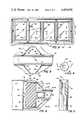
- FIG. 1is a front elevational view of a door with a light frame structure in accordance with one embodiment of the present invention
- FIG. 2is an enlarged, partial front elevational view of the light frame structure of FIG. 1;
- FIG. 3is a partial, side elevational view in section taken along lines 3--3 of FIG. 2;
- FIG. 4is a top plan view of a retainer of the light structure of FIG. 1;
- FIG. 5is a side elevational view in section taken along lines 5--5 of FIG. 4;
- FIG. 6is a partial, enlarged, top plan view in section taken lines 6--6 of FIG. 2 of the light structure;
- FIG. 7is a front elevational view of a door and light frame structure according to a second embodiment of the present invention.
- FIG. 8is an enlarged, partial front elevational view of the light structure of FIG. 7;
- FIG. 9is an enlarged, partial top plan view in section taken along lines 9--9 of FIG. 8 of the light structure.
- FIG. 10is a front elevational view of a light frame structure according to a third embodiment of the present invention.
- a door 12according to a first embodiment of the present invention has two separate door lights 14 mounted in the upper portion of the door.
- Each door lightcomprises a frame assembly 16 in which a translucent panel 18 is mounted.
- each frame assembly and panelis rectangular, the frame assembly and panel can be of any desired polygonal shape or be curvilinear.
- Metal door 12comprises two generally parallel, metal sheets 20,22 forming the major surfaces of the door and having decorative relief portions formed therein.
- the sheetsare connected by transverse edges with the void between the sheets and edges filled with an insulating foam material.
- the construction of the door itselfis conventional, and thus, is not described in detail.
- a rectangular opening 24is formed in the door for each door light 14.
- Each side of opening 24is defined by portions of sheet metal panels 20,22 provided in configurations adapted to receive frame assembly 16.
- the opening defining portions of each panelcomprise a first flange 26 bent perpendicular to the remainder of the panes 20,22 such that such portions extend inwardly toward the opposite panel.
- Each first flangeextends inwardly for a distance less than one-half the thickness of the door providing a space therebetween.
- a second flangeextends perpendicularly from each first flange toward the center of opening 24.
- Frame assembly 16includes an inner half-frame 30 and an outer half-frame 32 which are dimensioned to be received in rectangular opening 24 with translucent panel 18 sandwiched therebetween.
- Each of the half-frameshas substantially the same configuration and is unitarily formed from sheet metal with four side members of substantially identical cross section.
- the side membersinclude two horizontal members 34 and two vertical members 36.
- Each side membershas three portions, a flat portion 38, a face portion 40, and a third or inwardly extending portion 42.
- Each flat portionis adapted to lie in parallel contiguous relationship with one of the first flanges 26 defining opening 24 such that its inner distal edge abuts one of the second flanges 28. Since flat portions 38 are narrower than first flanges 26, the face portions are offset inwardly from the outer surfaces of door panels 20,22. Each face portion extends in a generally perpendicular direction from its flat portion toward the center of the opening.
- Two countersunk holes 46extend through the face portion of each of the two horizontal members 34 adjacent their junctures with vertical members 36.
- the third portionsextend generally inwardly from the face portions at obtuse angles toward the opposite side of the door.
- the third portionshave obtusely angled lips 44 at their distal edges which abut translucent panel 18.
- Each half-frameis formed as a continuous, unitary member from a single sheet of galvanized metal.
- the formation of the half-frame from the sheet metalis accomplished by cutting and stamping operations so as to facilitate mass production thereof. Since the half-frames are identical, only one type of half-frame need be formed and care need not be exercised as to which half-frame is placed on the inner surface of the door and which half-frame is placed on the outer surface of the door during assembly.
- Translucent panel 18is of generally conventional configuration comprising two rectangular glass panes 48 separated by an insulating member 50. However, any suitably translucent panel can be supported by the frame assembly of the present invention.
- the half-framesare secured to each other in door opening 24 and to translucent panel 18 by eight externally threaded fasteners 52 and four tubular retainers 54.
- the fastenersextend through holes 46 in half-frames 30,32.
- Each retaineris generally tubular or cylindrical and is formed of a plastic material, such as polyvinyl chloride or nylon. As illustrated in FIGS. 4 and 5, an axially extending bore 56 extends entirely through the retainer. Alternatively, two separate bores extending inwardly from the opposite axial ends of the retainer can be provided. The axial ends of internal bore 56 are formed with countersinks 58 to assist in aligning screws 52 with bore 56. On the exterior surface of each retainer, a plurality of parallel, axially extending beads 60 project outwardly. As will be explained hereinafter, these beads facilitate assembly of the frame assembly by inhibiting rotation of the retainers during threading of the fasteners in internal bore 56.
- the material of the retainerspermits threads to be formed in bore 56 for threadedly engaging the external threads on fastener 52 by the threading of the fasteners into the bores.
- the axial bore in each retaineris coaxially aligned with one of the holes 46 in each of the half-frames such that it threadedly receives two of the fasteners in its opposite ends.
- Retainers 54form a thermal break between inner half-frame 30 and outer half-frame 32 to inhibit the conduction of heat therebetween. Since fasteners 52 are separated by retainers 54, there is no direct metal-to-metal contact by the mechanism securing the half-frames together. The half-frames are also separated and insulated relative to each other by the translucent panel 28 and the glazing material therefor. The metal panels 20,22 of the door are also separated by the space between second flanges 28. Thus, there is no direct metal-to-metal contact by inner and outer members of the door and frame assembly of the present invention such that the door acts as an effective thermal insulator.
- insulating blocks or members 62are mounted between the half frames. These blocks extend laterally between retainers 54 and are sized to substantially fill the space between the peripheral edge of translucent panel 18 and second flanges 28.
- the insulating blockscan be formed of polystyrene foam (e.g. Styrofoam manufactured by Dow Chemical Company).
- Caulking tape 64provides a seal between half-frames 30,32 and translucent panel 18.
- the tapehas one surface bearing and adhesive which is adhered to the surface of the panel at locations spaced inwardly, but located adjacent the periphery of the panel, such that the edge of the tape closest to the panel center is aligned with the distal edge of lip 44.
- the tapeis 1/4 inch wide and 1/16 inch thick.
- retainer beads 62engage the peripheral edge of the translucent panel and/or insulating block 62 in order to inhibit rotation of the retainers during threading of the fasteners into bore 56.
- FIGS. 7-9A second embodiment of the present invention is illustrated in FIGS. 7-9.
- the second embodimentinvolves an elongated frame for forming an elongated door light.
- the features of the second embodimentwhich are substantially identical to those of the first embodiment are denoted with the same reference numerals.
- Door 66has a single elongated opening 68 formed adjacent its top portion.
- An elongated door light 70comprising a frame assembly 72 and a translucent panel 74 is mounted in door opening 68.
- Frame assembly 72comprises an inner half-frame 76 and an outer half-frame 78, with each half-frame having two opposite horizontal members 80 and two opposed vertical members 82.
- the vertical and horizontal membershave a plurality of holes 46 for receiving screws 52.
- the cross sectional configuration and the attachment of the vertical and horizontal members of half-frames 76,78are identical to those of the half-frames 30,32 and are illustrated in FIGS. 3 and 6.
- Half-frames 76,78also have muntins which are formed as unitary portions of each half-frame and extend perpendicular to horizontal members 80 and parallel to vertical members 82.
- the muntinsgive translucent panel 74 the appearance of comprising several separate panes, even though in fact it extends the entire extent of door light 70.
- each muntincomprises an outer flat portion 86 having inwardly and angularly extending portions 88 extending from the lateral sides thereof. Portions 88 terminate in lips 90 which are sealed to translucent panel 74 by glazing tape 64.
- FIG. 10A third embodiment of the present invention is illustrated in FIG. 10.
- the door light 92is elongated in a vertical direction and is of a form suitable for providing a sidelight in a door frame. This sidelight can be provided with or without muntins.
- the frame assembly and translucent panel of sidelight 92are formed similarly to the arrangement disclosed for door lights 14,70.
Landscapes
- Engineering & Computer Science (AREA)
- Civil Engineering (AREA)
- Structural Engineering (AREA)
- Securing Of Glass Panes Or The Like (AREA)
Abstract
Description
Claims (16)
Priority Applications (1)
| Application Number | Priority Date | Filing Date | Title |
|---|---|---|---|
| US06/389,887US4430836A (en) | 1982-06-18 | 1982-06-18 | Frame assembly for door light |
Applications Claiming Priority (1)
| Application Number | Priority Date | Filing Date | Title |
|---|---|---|---|
| US06/389,887US4430836A (en) | 1982-06-18 | 1982-06-18 | Frame assembly for door light |
Publications (1)
| Publication Number | Publication Date |
|---|---|
| US4430836Atrue US4430836A (en) | 1984-02-14 |
Family
ID=23540155
Family Applications (1)
| Application Number | Title | Priority Date | Filing Date |
|---|---|---|---|
| US06/389,887Expired - LifetimeUS4430836A (en) | 1982-06-18 | 1982-06-18 | Frame assembly for door light |
Country Status (1)
| Country | Link |
|---|---|
| US (1) | US4430836A (en) |
Cited By (21)
| Publication number | Priority date | Publication date | Assignee | Title |
|---|---|---|---|---|
| US4897975A (en)* | 1987-10-23 | 1990-02-06 | Odl, Incorporated | Integral door light with glazing stop |
| US4920718A (en)* | 1988-03-17 | 1990-05-01 | Odl, Incorporated | Integral door light and related door construction |
| US5175970A (en)* | 1990-06-22 | 1993-01-05 | Pease Industries, Inc. | Molded panel door with integral raised trim |
| US5323579A (en)* | 1992-12-16 | 1994-06-28 | Masco Industries, Inc. | Door window glass and frame assembly |
| US5439282A (en)* | 1992-08-18 | 1995-08-08 | Siemens Aktiengesellschaft | Door for a switch cabinet, with a frame to be installed on the inner side |
| US5644874A (en)* | 1995-04-03 | 1997-07-08 | General Products Company, Inc. | Light frame system |
| US5749184A (en)* | 1995-04-03 | 1998-05-12 | General Products Company, Inc. | Light frame system with fastener clips |
| USD470242S1 (en) | 2001-07-06 | 2003-02-11 | Andersen Corporation | Slab door portion |
| US20070169427A1 (en)* | 2006-01-24 | 2007-07-26 | Lee David E Iii | Decorative grid system and method |
| US7318301B2 (en) | 1997-10-24 | 2008-01-15 | Custom Glass Products Of Carolina, Inc. | Window, muntin and method |
| US20080163572A1 (en)* | 2006-01-24 | 2008-07-10 | David Eugene Lee | Decorative grid system and method |
| US9016030B1 (en)* | 2014-06-10 | 2015-04-28 | Ryan D. Steele | Metal door |
| US9022091B2 (en) | 2013-03-13 | 2015-05-05 | Clopay Building Products Company, Inc. | Impact window assembly for overhead door |
| US9175508B1 (en)* | 2014-06-10 | 2015-11-03 | Ryan D. Steele | Metal door |
| US9506247B2 (en) | 2014-03-28 | 2016-11-29 | Steelcase Inc. | Transparent panel system for partitions |
| US10329759B2 (en) | 2012-09-17 | 2019-06-25 | Steelcase Inc. | Floor-to-ceiling partition wall assembly |
| US11384595B1 (en)* | 2021-09-27 | 2022-07-12 | Lisa Harrington | Securable pet door |
| US20230091125A1 (en)* | 2020-06-01 | 2023-03-23 | Sekisui House, Ltd. | Post and beam structure at a multi-height opening portion |
| US11702885B1 (en) | 2022-06-09 | 2023-07-18 | Lisa Harrington | Securable pet door |
| US11788346B2 (en) | 2021-09-27 | 2023-10-17 | Lisa Harrington | Securable pet door |
| US12435561B2 (en) | 2021-09-27 | 2025-10-07 | Lisa E. Harrington | Securable pet door |
Citations (24)
| Publication number | Priority date | Publication date | Assignee | Title |
|---|---|---|---|---|
| US812467A (en)* | 1905-01-21 | 1906-02-13 | John W Watkins | Sheet-metal window-sash. |
| US1287888A (en)* | 1915-01-12 | 1918-12-17 | Empire Art Metal Co Inc | Door and like metallic structure. |
| US1947736A (en)* | 1933-03-06 | 1934-02-20 | Ainsworth Mfg Corp | Frame corner bead |
| US2365954A (en)* | 1942-06-17 | 1944-12-26 | Herold H Hebestreit | Window sash |
| US2402105A (en)* | 1943-03-08 | 1946-06-11 | Adlake Co | Multiple glass sash |
| US2654920A (en)* | 1950-05-27 | 1953-10-13 | Victor M Langsett | Insulated metal window closure |
| US2767814A (en)* | 1953-06-15 | 1956-10-23 | Fenestra Inc | Clip for storm window insulating strip |
| US2808355A (en)* | 1956-06-11 | 1957-10-01 | North American Aviation Inc | Glass enclosure |
| US2860744A (en)* | 1955-03-07 | 1958-11-18 | Conjaur Corp | Adjustable door frames |
| US3004641A (en)* | 1959-01-29 | 1961-10-17 | Robert C Johnson | Hollow metal doors |
| US3014560A (en)* | 1955-01-12 | 1961-12-26 | Republic Steel Corp | Building panel |
| US3099865A (en)* | 1961-04-10 | 1963-08-06 | Alice W Burnett | Window structure |
| US3191727A (en)* | 1962-11-06 | 1965-06-29 | Aluminum Co Of America | Framing structures |
| US3340661A (en)* | 1965-05-05 | 1967-09-12 | Mannsville Plastics Inc | Ornamental grill |
| US3381431A (en)* | 1967-06-02 | 1968-05-07 | Allan I. Jacobson | Mullion device for window |
| US3487602A (en)* | 1967-05-24 | 1970-01-06 | American Welding Mfg Co | Window frame and glazing members for a metal door |
| US3599703A (en)* | 1969-03-17 | 1971-08-17 | Anthony R Mennuto | Insulated storm door assembly |
| US3641721A (en)* | 1970-02-25 | 1972-02-15 | Rimar Mfg Inc | Maintenance-free door light insert assembly |
| US3686814A (en)* | 1970-02-02 | 1972-08-29 | Anderson Mfg Co V E | False window muntin bar structure |
| US3800489A (en)* | 1972-01-03 | 1974-04-02 | Structural Syst Inc | Modular wall construction |
| US3949526A (en)* | 1974-07-31 | 1976-04-13 | H. A. Brown Limited | Door construction |
| US4110948A (en)* | 1977-03-11 | 1978-09-05 | Maier Jr Adolph J | Thermal insulating clips for metal insulated walls and roofs |
| US4162590A (en)* | 1978-01-16 | 1979-07-31 | Earley Vernon A | Burglar bar apparatus |
| US4214415A (en)* | 1978-10-16 | 1980-07-29 | Swiss Aluminium Ltd. | Expanded store front system |
- 1982
- 1982-06-18USUS06/389,887patent/US4430836A/ennot_activeExpired - Lifetime
Patent Citations (24)
| Publication number | Priority date | Publication date | Assignee | Title |
|---|---|---|---|---|
| US812467A (en)* | 1905-01-21 | 1906-02-13 | John W Watkins | Sheet-metal window-sash. |
| US1287888A (en)* | 1915-01-12 | 1918-12-17 | Empire Art Metal Co Inc | Door and like metallic structure. |
| US1947736A (en)* | 1933-03-06 | 1934-02-20 | Ainsworth Mfg Corp | Frame corner bead |
| US2365954A (en)* | 1942-06-17 | 1944-12-26 | Herold H Hebestreit | Window sash |
| US2402105A (en)* | 1943-03-08 | 1946-06-11 | Adlake Co | Multiple glass sash |
| US2654920A (en)* | 1950-05-27 | 1953-10-13 | Victor M Langsett | Insulated metal window closure |
| US2767814A (en)* | 1953-06-15 | 1956-10-23 | Fenestra Inc | Clip for storm window insulating strip |
| US3014560A (en)* | 1955-01-12 | 1961-12-26 | Republic Steel Corp | Building panel |
| US2860744A (en)* | 1955-03-07 | 1958-11-18 | Conjaur Corp | Adjustable door frames |
| US2808355A (en)* | 1956-06-11 | 1957-10-01 | North American Aviation Inc | Glass enclosure |
| US3004641A (en)* | 1959-01-29 | 1961-10-17 | Robert C Johnson | Hollow metal doors |
| US3099865A (en)* | 1961-04-10 | 1963-08-06 | Alice W Burnett | Window structure |
| US3191727A (en)* | 1962-11-06 | 1965-06-29 | Aluminum Co Of America | Framing structures |
| US3340661A (en)* | 1965-05-05 | 1967-09-12 | Mannsville Plastics Inc | Ornamental grill |
| US3487602A (en)* | 1967-05-24 | 1970-01-06 | American Welding Mfg Co | Window frame and glazing members for a metal door |
| US3381431A (en)* | 1967-06-02 | 1968-05-07 | Allan I. Jacobson | Mullion device for window |
| US3599703A (en)* | 1969-03-17 | 1971-08-17 | Anthony R Mennuto | Insulated storm door assembly |
| US3686814A (en)* | 1970-02-02 | 1972-08-29 | Anderson Mfg Co V E | False window muntin bar structure |
| US3641721A (en)* | 1970-02-25 | 1972-02-15 | Rimar Mfg Inc | Maintenance-free door light insert assembly |
| US3800489A (en)* | 1972-01-03 | 1974-04-02 | Structural Syst Inc | Modular wall construction |
| US3949526A (en)* | 1974-07-31 | 1976-04-13 | H. A. Brown Limited | Door construction |
| US4110948A (en)* | 1977-03-11 | 1978-09-05 | Maier Jr Adolph J | Thermal insulating clips for metal insulated walls and roofs |
| US4162590A (en)* | 1978-01-16 | 1979-07-31 | Earley Vernon A | Burglar bar apparatus |
| US4214415A (en)* | 1978-10-16 | 1980-07-29 | Swiss Aluminium Ltd. | Expanded store front system |
Cited By (21)
| Publication number | Priority date | Publication date | Assignee | Title |
|---|---|---|---|---|
| US4897975A (en)* | 1987-10-23 | 1990-02-06 | Odl, Incorporated | Integral door light with glazing stop |
| US4920718A (en)* | 1988-03-17 | 1990-05-01 | Odl, Incorporated | Integral door light and related door construction |
| US5175970A (en)* | 1990-06-22 | 1993-01-05 | Pease Industries, Inc. | Molded panel door with integral raised trim |
| US5439282A (en)* | 1992-08-18 | 1995-08-08 | Siemens Aktiengesellschaft | Door for a switch cabinet, with a frame to be installed on the inner side |
| US5323579A (en)* | 1992-12-16 | 1994-06-28 | Masco Industries, Inc. | Door window glass and frame assembly |
| US5644874A (en)* | 1995-04-03 | 1997-07-08 | General Products Company, Inc. | Light frame system |
| US5749184A (en)* | 1995-04-03 | 1998-05-12 | General Products Company, Inc. | Light frame system with fastener clips |
| US7318301B2 (en) | 1997-10-24 | 2008-01-15 | Custom Glass Products Of Carolina, Inc. | Window, muntin and method |
| USD470242S1 (en) | 2001-07-06 | 2003-02-11 | Andersen Corporation | Slab door portion |
| US20080163572A1 (en)* | 2006-01-24 | 2008-07-10 | David Eugene Lee | Decorative grid system and method |
| US20070169427A1 (en)* | 2006-01-24 | 2007-07-26 | Lee David E Iii | Decorative grid system and method |
| US10329759B2 (en) | 2012-09-17 | 2019-06-25 | Steelcase Inc. | Floor-to-ceiling partition wall assembly |
| US9022091B2 (en) | 2013-03-13 | 2015-05-05 | Clopay Building Products Company, Inc. | Impact window assembly for overhead door |
| US9506247B2 (en) | 2014-03-28 | 2016-11-29 | Steelcase Inc. | Transparent panel system for partitions |
| US9016030B1 (en)* | 2014-06-10 | 2015-04-28 | Ryan D. Steele | Metal door |
| US9175508B1 (en)* | 2014-06-10 | 2015-11-03 | Ryan D. Steele | Metal door |
| US20230091125A1 (en)* | 2020-06-01 | 2023-03-23 | Sekisui House, Ltd. | Post and beam structure at a multi-height opening portion |
| US11384595B1 (en)* | 2021-09-27 | 2022-07-12 | Lisa Harrington | Securable pet door |
| US11788346B2 (en) | 2021-09-27 | 2023-10-17 | Lisa Harrington | Securable pet door |
| US12435561B2 (en) | 2021-09-27 | 2025-10-07 | Lisa E. Harrington | Securable pet door |
| US11702885B1 (en) | 2022-06-09 | 2023-07-18 | Lisa Harrington | Securable pet door |
Similar Documents
| Publication | Publication Date | Title |
|---|---|---|
| US4430836A (en) | Frame assembly for door light | |
| US5765325A (en) | Hurricane door light | |
| US4621478A (en) | Extruded plastic flush stop window mullion and framing system | |
| US4920718A (en) | Integral door light and related door construction | |
| US3093217A (en) | Insulating unit for curtain wall | |
| US5058344A (en) | Wall panel system | |
| US3918231A (en) | Frost resistant window sash | |
| US4841700A (en) | Narrow flush glazed thermal framing | |
| US4250673A (en) | Window replacement system | |
| US3108336A (en) | Window muntin bar elements | |
| US4423582A (en) | Glass door and window structures | |
| US4525961A (en) | Double-glazed window for insertion in openings in walls or doors of a sandwich-type construction | |
| JPH04333791A (en) | Device for unifying large number of glass panel | |
| US4223499A (en) | Decorative stained glass insert unit for windows | |
| US4115964A (en) | Windows and method of making the same | |
| JP2659519B2 (en) | Frame and closing plate mounting structure to frame | |
| US3001245A (en) | Building structure | |
| US5136812A (en) | Top hinged sash construction and associated window construction and related methods | |
| US4596099A (en) | Heat-insulating frame assembly for use in curtain wall construction | |
| US8028479B2 (en) | Interlocking structural glazing panels | |
| JPH0248620Y2 (en) | ||
| JP3448762B2 (en) | Metal-resin composite frame and glass shoji | |
| US3834097A (en) | Double glazed window assembly | |
| JPH0119747Y2 (en) | ||
| JP2002201864A (en) | Installing method of window frame in externally sticking heat insulating construction method and outer architrave |
Legal Events
| Date | Code | Title | Description |
|---|---|---|---|
| AS | Assignment | Owner name:GENERAL PRODUCTS COMPANY, INC., FREDEICKSBURG, VA. Free format text:ASSIGNMENT OF ASSIGNORS INTEREST.;ASSIGNOR:MC KANN, H. SMITH;REEL/FRAME:004016/0743 Effective date:19820602 | |
| STCF | Information on status: patent grant | Free format text:PATENTED CASE | |
| MAFP | Maintenance fee payment | Free format text:PAYMENT OF MAINTENANCE FEE, 4TH YEAR, PL 96-517 (ORIGINAL EVENT CODE: M170); ENTITY STATUS OF PATENT OWNER: SMALL ENTITY Year of fee payment:4 | |
| MAFP | Maintenance fee payment | Free format text:PAYMENT OF MAINTENANCE FEE, 8TH YEAR, PL 96-517 (ORIGINAL EVENT CODE: M171); ENTITY STATUS OF PATENT OWNER: SMALL ENTITY Year of fee payment:8 | |
| FEPP | Fee payment procedure | Free format text:PAYOR NUMBER ASSIGNED (ORIGINAL EVENT CODE: ASPN); ENTITY STATUS OF PATENT OWNER: SMALL ENTITY | |
| REFU | Refund | Free format text:REFUND - PAYMENT OF MAINTENANCE FEE, 12TH YEAR, LARGE ENTITY (ORIGINAL EVENT CODE: R185); ENTITY STATUS OF PATENT OWNER: SMALL ENTITY | |
| FEPP | Fee payment procedure | Free format text:PAT HLDR NO LONGER CLAIMS SMALL ENT STAT AS INDIV INVENTOR (ORIGINAL EVENT CODE: LSM1); ENTITY STATUS OF PATENT OWNER: SMALL ENTITY | |
| MAFP | Maintenance fee payment | Free format text:PAYMENT OF MAINTENANCE FEE, 12TH YR, SMALL ENTITY (ORIGINAL EVENT CODE: M285); ENTITY STATUS OF PATENT OWNER: SMALL ENTITY Year of fee payment:12 | |
| FEPP | Fee payment procedure | Free format text:PAT HOLDER CLAIMS SMALL ENTITY STATUS - SMALL BUSINESS (ORIGINAL EVENT CODE: SM02); ENTITY STATUS OF PATENT OWNER: SMALL ENTITY | |
| AS | Assignment | Owner name:THERMA-TRU VIRGINIA LIMITED COMPANY, VIRGINIA Free format text:ASSIGNMENT OF ASSIGNORS INTEREST;ASSIGNOR:GENERAL PRODUCTS COMPANY, INC.;REEL/FRAME:010804/0093 Effective date:20000424 | |
| AS | Assignment | Owner name:THERMA-TRU HOLDINGS, INC., OHIO Free format text:ASSIGNMENT OF ASSIGNORS INTEREST;ASSIGNOR:THERMA-TRU CORP.;REEL/FRAME:010832/0638 Effective date:20000508 | |
| AS | Assignment | Owner name:GENERAL ELECTRIC CAPITAL CORPORATION, NEW YORK Free format text:SECURITY INTEREST;ASSIGNORS:THERMA-TRU CORP.;THERMA-TRU HOLDINGS, INC.;THERMA-TRU VIRGINIA LIMITED COMPANY;AND OTHERS;REEL/FRAME:013868/0055 Effective date:20030220 |