US4429741A - Self powered downhole tool anchor - Google Patents
Self powered downhole tool anchorDownload PDFInfo
- Publication number
- US4429741A US4429741AUS06/310,571US31057181AUS4429741AUS 4429741 AUS4429741 AUS 4429741AUS 31057181 AUS31057181 AUS 31057181AUS 4429741 AUS4429741 AUS 4429741A
- Authority
- US
- United States
- Prior art keywords
- housing
- inner mandrel
- firing
- adjacent
- downhole tool
- Prior art date
- Legal status (The legal status is an assumption and is not a legal conclusion. Google has not performed a legal analysis and makes no representation as to the accuracy of the status listed.)
- Expired - Fee Related
Links
- 238000010304firingMethods0.000claimsabstractdescription64
- 239000012530fluidSubstances0.000claimsabstractdescription36
- 239000000463materialSubstances0.000claimsabstractdescription26
- 239000002775capsuleSubstances0.000claimsabstractdescription16
- 230000000717retained effectEffects0.000claimsabstractdescription9
- 238000006073displacement reactionMethods0.000claimsabstractdescription4
- 230000013011matingEffects0.000claimsdescription13
- 239000003380propellantSubstances0.000claimsdescription7
- 238000007789sealingMethods0.000claimsdescription4
- 230000008878couplingEffects0.000claims4
- 238000010168coupling processMethods0.000claims4
- 238000005859coupling reactionMethods0.000claims4
- 230000003116impacting effectEffects0.000claims2
- 238000004873anchoringMethods0.000description4
- 230000006835compressionEffects0.000description4
- 238000007906compressionMethods0.000description4
- 239000002360explosiveSubstances0.000description3
- 239000008186active pharmaceutical agentSubstances0.000description2
- 238000005553drillingMethods0.000description2
- 239000000203mixtureSubstances0.000description2
- 238000012986modificationMethods0.000description2
- 230000004048modificationEffects0.000description2
- 239000000843powderSubstances0.000description2
- DHEQXMRUPNDRPG-UHFFFAOYSA-Nstrontium nitrateChemical compound[Sr+2].[O-][N+]([O-])=O.[O-][N+]([O-])=ODHEQXMRUPNDRPG-UHFFFAOYSA-N0.000description2
- 239000005062PolybutadieneSubstances0.000description1
- ZLMJMSJWJFRBEC-UHFFFAOYSA-NPotassiumChemical compound[K]ZLMJMSJWJFRBEC-UHFFFAOYSA-N0.000description1
- 238000010276constructionMethods0.000description1
- 230000008602contractionEffects0.000description1
- 239000002657fibrous materialSubstances0.000description1
- 239000004615ingredientSubstances0.000description1
- 229910052751metalInorganic materials0.000description1
- 239000002184metalSubstances0.000description1
- 239000000123paperSubstances0.000description1
- 239000004033plasticSubstances0.000description1
- 229920002857polybutadienePolymers0.000description1
- 229910052700potassiumInorganic materials0.000description1
- 239000011591potassiumSubstances0.000description1
- 238000010008shearingMethods0.000description1
- 239000007787solidSubstances0.000description1
- 238000013022ventingMethods0.000description1
Images
Classifications
- E—FIXED CONSTRUCTIONS
- E21—EARTH OR ROCK DRILLING; MINING
- E21B—EARTH OR ROCK DRILLING; OBTAINING OIL, GAS, WATER, SOLUBLE OR MELTABLE MATERIALS OR A SLURRY OF MINERALS FROM WELLS
- E21B7/00—Special methods or apparatus for drilling
- E21B7/04—Directional drilling
- E21B7/06—Deflecting the direction of boreholes
- E21B7/061—Deflecting the direction of boreholes the tool shaft advancing relative to a guide, e.g. a curved tube or a whipstock
- E—FIXED CONSTRUCTIONS
- E21—EARTH OR ROCK DRILLING; MINING
- E21B—EARTH OR ROCK DRILLING; OBTAINING OIL, GAS, WATER, SOLUBLE OR MELTABLE MATERIALS OR A SLURRY OF MINERALS FROM WELLS
- E21B23/00—Apparatus for displacing, setting, locking, releasing or removing tools, packers or the like in boreholes or wells
- E21B23/04—Apparatus for displacing, setting, locking, releasing or removing tools, packers or the like in boreholes or wells operated by fluid means, e.g. actuated by explosion
- E21B23/0411—Apparatus for displacing, setting, locking, releasing or removing tools, packers or the like in boreholes or wells operated by fluid means, e.g. actuated by explosion specially adapted for anchoring tools or the like to the borehole wall or to well tube
- E21B23/04115—Apparatus for displacing, setting, locking, releasing or removing tools, packers or the like in boreholes or wells operated by fluid means, e.g. actuated by explosion specially adapted for anchoring tools or the like to the borehole wall or to well tube using radial pistons
- E—FIXED CONSTRUCTIONS
- E21—EARTH OR ROCK DRILLING; MINING
- E21B—EARTH OR ROCK DRILLING; OBTAINING OIL, GAS, WATER, SOLUBLE OR MELTABLE MATERIALS OR A SLURRY OF MINERALS FROM WELLS
- E21B23/00—Apparatus for displacing, setting, locking, releasing or removing tools, packers or the like in boreholes or wells
- E21B23/04—Apparatus for displacing, setting, locking, releasing or removing tools, packers or the like in boreholes or wells operated by fluid means, e.g. actuated by explosion
- E21B23/0411—Apparatus for displacing, setting, locking, releasing or removing tools, packers or the like in boreholes or wells operated by fluid means, e.g. actuated by explosion specially adapted for anchoring tools or the like to the borehole wall or to well tube
- E—FIXED CONSTRUCTIONS
- E21—EARTH OR ROCK DRILLING; MINING
- E21B—EARTH OR ROCK DRILLING; OBTAINING OIL, GAS, WATER, SOLUBLE OR MELTABLE MATERIALS OR A SLURRY OF MINERALS FROM WELLS
- E21B23/00—Apparatus for displacing, setting, locking, releasing or removing tools, packers or the like in boreholes or wells
- E21B23/04—Apparatus for displacing, setting, locking, releasing or removing tools, packers or the like in boreholes or wells operated by fluid means, e.g. actuated by explosion
- E21B23/0414—Apparatus for displacing, setting, locking, releasing or removing tools, packers or the like in boreholes or wells operated by fluid means, e.g. actuated by explosion using explosives
- E—FIXED CONSTRUCTIONS
- E21—EARTH OR ROCK DRILLING; MINING
- E21B—EARTH OR ROCK DRILLING; OBTAINING OIL, GAS, WATER, SOLUBLE OR MELTABLE MATERIALS OR A SLURRY OF MINERALS FROM WELLS
- E21B23/00—Apparatus for displacing, setting, locking, releasing or removing tools, packers or the like in boreholes or wells
- E21B23/06—Apparatus for displacing, setting, locking, releasing or removing tools, packers or the like in boreholes or wells for setting packers
- E21B23/065—Apparatus for displacing, setting, locking, releasing or removing tools, packers or the like in boreholes or wells for setting packers setting tool actuated by explosion or gas generating means
Definitions
- the inventionrelates to a mechanical self powered fluid pressure actuated apparatus for anchoring a preattached downhole tool to a well bore casing in a single trip into the well bore.
- the inventionconcerns an anchor device to which a downhole tool such as a whipstock and casing bit assembly may be preattached, supported and lowered, together as unit by connection to a drill string, in a single trip for attachment to a well bore casing and various purposes such as side tracking or deviating the bore.
- a downhole toolsuch as a whipstock and casing bit assembly
- the anchor deviceis of the type in which a mechanical firing means ignites a self contained cartridge of fluid pressure generating material.
- the fluid pressureacts against a piston, fluid and piston to shear a pin, displace a tapered mandrel and radially displace slips into gripping engagement with the side wall of the well bore casing or well bore.
- downhole tools of various typeshave been anchored to a well casing after a number of trips into the bore by radially expandable slips actuated by various self contained fluid pressure generating devices.
- the fluid pressureis usually generated by igniting combustible material of various types including explosives, and chemically reactive ingredients adapted to produce fluid pressure of sufficient magnitude to actuate the device.
- Various means for igniting and mixing the materialsare known including electrically and mechanically fired explosive charges, bullets, and other projectiles.
- the Applicant's anchordiffers from the prior art in that it allows for preattachment of the downhole tool thereto for a single trip by drill string into the bore for attaching the entire assembly to the casing.
- a preloaded mechanical firing mechanismincludes a trigger foot that forcefully engages the bottom or plug in the well bore and which under the weight of the assembly applied thereto, shears pins and releases a preloaded hammer. The hammer strikes and propels a firing pin into the igniter of a cartridge of combustible material which forms to generate the fluid pressure and radially expand the anchoring slips into gripping contact with the casing.
- a self powered fluid pressure actuatable well bore tool anchor devicecomprises an inner cylindrical mandrel containing fluid and a piston therein.
- the inner mandrelhas radial openings in its sidewall and an end cap adapted for preattachment to the mating lower end of a well bore tool such as a whipstock adapted at its upper opposite end for preattachment preferrably to a drill bit attached to a drill string for simultaneously supporting and lowering the preattached well bore tool and anchor device into a well bore casing.
- Attached to the lower end of the inner mandrelis a lower externally tapered slip expander cone keyed to and engaging the lower internally tapered portion of a plurality of radially expandable outer toothed slips.
- An upper outer expander tube and pistonextending around and connected by a shear pin to the inner mandrel is provided with a lower externally tapered end mandrel cone engaging and mating with upper internally tapered portions of the inwardly resiliently biased slips.
- a slotted slip housing attached by a shear pin to the upper expander tubeholds the slips, movable radially within the slots, in predetermined axial and angularly spaced positions.
- a radially expandable split rachet ring with internal teeth axially movable with the upper expander tubeis provided for cooperating locking engagement with external teeth on the inner mandrel.
- a self contained source of powercomprises a cartridge of combustible material and ignitor adapted to generate fluid pressure is retained within an upper portion of a power supply housing attached to the lower end of the lower expander cone.
- a mechanical firing meanscomprising a firing pin, preloaded hammer trigger device are housed within a firing means housing and maintained in a cocked position by one or more shear pins.
- a triggerincluding a foot adapted to rest on the bottom of or a plug in the well bore engages a trigger spring housing in contact with a preloaded spring and the hammer. Downward movement of the assembly relative to the trigger device causes the pin to shear and release the spring loaded hammer which strikes and propels the firing pin into the primer to ignite the combustible material.
- the materialburns and creates fluid or gas pressure that acts against piston and fluid which acts between the inner mandrel and outer mandrel and piston to shear pins and allow axial movement of the outer mandrel and slips relative to the lower expander cone, and shear another pin which allows upper expander tube and ratchet cone to move downwardly, expand and lock the slips against the casing wall.
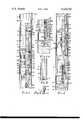
- FIG. 1is a view in elevation and partly in section of the upper and central portion of the anchor device situated within a well bore casing and attached at its upper end to the mating lower end of a whipstock downhole tool for deviating the well bore;
- FIG. 1Ais a view partly in elevation and partly in section of the remaining lower portion of the anchor device engaging the bottom or plug situated in the well bore casing;
- FIG. 2is a view partly in elevation and partly in section of the anchor device after being actuated and in gripping engagement with the well bore casing;
- FIG. 3is a sectional view through the self contained cartridge of fluid pressure generating material.
- FIG. 4is a view of the upper portion of the whipstock of FIG. 1 preconnected to a drill bit attached to the drill string for supporting the entire assembly.
- a self powered anchor device 10having an end cap or upper end portion 12 adapted for and connected by a clevis pin P to the inserted mating lower end portion of a downhole tool T.
- the tool Tis preferrably preattached as shown in FIG. 4 by a shear bolt to a drill bit D attached to the end of supporting drill string Ds in a manner similar to that shown in U.S. Pat. No. 3,908,759.
- itcould be adapted for direct preattachment to the drill string.
- the drill stringsupports the bit, downhole tool and attached anchor assembly for a single downhole trip and attachment to the well bore casing C.
- the downhole tool T of which an upper portion is shown in FIG. 4 and the lower portion is shown in FIG. 1is a whipstock W utilized in the well known manner for deviating the well bore by first drilling a window in the casing C with the pilot bit D shown guided by the oriented inclined side of the whipstock W.
- other downhole toolssuch as perforators, packers, side corers and many other devices may be adapted for attachment to the anchor device of the invention.
- the end cap 12has a central bore 14 plugged by a removable pipe plug 16 in a lower externally threaded end portion thereof sealingly attached to the upper internally threading end of an inner cylindrical or tubular mandrel 20 extending axially to a lower open end thereof.
- a resiliently biased ball type pressure relief valve RVis connected to the bore 14 in the end cap for venting pressure above a critical level from the device.
- Inner mandrel 20has an upper sidewall portion with one or more fluid passages 22 extending laterally therethrough, an intermediate portion with external ratchet engaging teeth 24, a lower externally threaded end portion and an internal chamber 28.
- a piston 30 including annular seals and grooves thereinis retained in the chamber 28, by an annular stop or snap ring 32, for sealing sliding engagement with the mandrel sidewall and seals of the lower open end of the chamber containing a fluid F above the piston.
- the fluid Fis contained in the chamber 28 between the piston 30 and plug 16 in the end cap 12 and extends through the apertures 22 to an annular sealed space around the exterior of the inner mandrel 20.
- an internally threaded and sealed lower tapered slip expander or cone 34On, attached or threaded to the lower end of the inner mandrel 20 is an internally threaded and sealed lower tapered slip expander or cone 34.
- Fixed to the lower cone 34are equally angularly spaced tapered key ways and keys 36 each adapted for mating, guiding engagement with a lower internally tapered end portion of radially expandable gripping slips 38 with mating internally tapered surfaces, keyways and external gripping teeth or serrations.
- the keys and keywayprevent relative rotation but allow axial movement between slips and cones.
- Each slip 38has upper and lower oppositely tapered internal surfaces resiliently held in mating engagement with similarly oppositely tapered mating external surfaces of axially spaced lower and upper expander cones 34 and 40.
- the upper expander cone 40maybe an integral portion of, but is preferrably attached with suitable fasteners or screws shown to the lower end portion of an outer annular tubular piston or cylindrical outer mandrel and piston 44.
- the outer mandrel 44has an internal annular piston surface area adjacent the fluid passages 22 and is slideable on, sealingly engaged with and attached to the upper end portion of the inner mandrel 20 by at least one but preferably a plurality of shear screws 46.
- a tubular slip housing or sleeve 50provided with angular spaced windows or openings in its sidewall for initial displacement of and holding the slips 38 in the angularly spaced positions is attached by one or more shear pins or screws 52 to the upper cone 40.
- the housing 50extends downwardly to a lower end portion thereof situated adjacent an exterior channel or recess in each slip 38.
- Angularly spaced pins, studs, or projections 54 attached to the housing 50extend inwardly into the channels.
- Resilient meanssuch as compression springs 56 recessed into each of the slips 38 and inserted over the pins 54 are provided between the housing 50 and slips 38 for resiliently maintaining the slips retracted and in mating contact with tapered surfaces of cones 34 and 40.
- ratchet means 60for locking and preventing retracted axial movement of the cones 30 and 40 away from the radially expanded slips 38.
- the ratchet meanscomprises cooperating external ratchet teeth on the intermediate portion of inner mandrel and mating internal ratchet teeth on a radially expandable resilient split ratchet ring or annular pawl 62.
- the resilient split ring or pawl 62is situated within an internal annular groove and between opposing shoulders of the upper cone 40 and the attached outer mandrel and piston 44. Hence, relative axial movement between the outer and inner mandrels 44 and 20 in one direction moves the pawl 62, and causes the cooperating upper tapered sides of the internal ratchet teeth to slide over the external ratchet teeth of the inner mandrel 20. Simultaneously therewith, the ring 62 expands radially sufficiently to disengage and advance its internal ratchet teeth for contraction into locking mating engagement with the straight radial bottom or lower opposite sides of other adjacent external teeth of the inner mandrel 20.
- the split annular pawl or ring 62prevents reverse relative movement between the mandrels, cones and slips 38 and thereby maintains the anchoring engagement between the expanded slips 38 and sidewall of the casing C.
- Self contained power supply means or unit 70comprising a housing 72 threadedly attached and locked to the lower internally threaded end of the lower expander cone 34 on inner mandrel 20.
- the cartridge housing 72has, adjacent the lower end of the chamber 28 in the inner mandrel 20, an elongated internal sealed chamber containing a self contained canister PS of ignitable fluid or gas pressure generating material.
- the canistercomprises as shown in FIG. 3 agenerally hollow holder or shell casing S of any suitable metal, plastic, paper or fiber material having an open exit or outlet end thereof situated opposite an integral or separate shouldered or flanged head H fixed to the opposite end of the shell casing S.
- An integral annular flange or shoulder Fextends radially outwardly from the head H for engagement with the lower opposite end of the housing 72 and adjacent cartridge retainer means in the firing mechanism 80.
- a central bore in the head Hcontains a primer or ignitor I of conventional suitable construction in the form of a center fire cartridge or capsule pressed into the central bore.
- the capsule Icontains a small charge of pyrotechnic powder ignitor material for simultaneously igniting the main outer annular charge of fluid pressure generating and propellant material M.
- the propellant material Mis preferably a type of combustible material that burns at a much slower rate than conventional explosive materials do.
- a suitable slow burning pressure generating materialis preferably a mixture of strontium nitrate, potassium percholrate and poly butadiene oxiamide. A similar but more rapid burning mixture may be used as the primer ignitor material.
- the firing meanscomprises a preloaded firing mechanism 80 preassembled within an outer firing mechanism body or housing 82 threadedly attached as a unit to the lower externally threaded end of the power supply cartridge housing 72.
- firing pin meansincluding a firing pin housing 84, and an abutting firing pin guide housing or retaining ring 86 with a central bore into which a firing pin guide 88 is inserted and retained by an internal expandable snap ring.
- An upper or forward striker end of a firing pin 90is slidably and sealably mounted in a central guide way or bore of the guide member 88 and adapted for striking the ignitor capsule I adjacent thereto.
- the firing pin 90is normally resiliently biased away from the igniter capsule I and against a stop or retainer ring by resilient means such as a light compression spring 92 extending around an intermediate portion of the firing pin 90 within a central bore of the housing 84.
- the spring 92extends axially between an internal shoulder of the housing 84 and an annular shoulder or flange at the opposite end of the firing pin 90 and only applies a light force sufficient to maintain the firing pins in the retracted position shown against the stop against the action of external pressure.
- a firing pin hammer meansAdjacent to and abutting the lower end of the firing pin housing 84 is a firing pin hammer means including a hammer means or trigger housing 96 in a central bore of which a preloaded trigger or hammer 98 is slidably mounted.
- the hammer 98is retained in a cocked position by engagement of a preloaded resilient compression spring 100 therewith and the opposing strength of one or more shear screws or pins 101 projecting through the sidwall of the housing 96 and into obstructing engagement with a side surface or recessed shoulder in the side of the hammer 98.
- a preloaded or precompressed compression spring 100is situated within the internal bore of a generally cup shape trigger sleeve and or spring housing or cup 102 mounted within the hammer housing or casing 96.
- the spring 100is compressed between and extends axially from the annular bottom or end of spring housing and or trigger sleeve 102 to a recessed annular shoulder or surface adjacent the opposite lower projecting pilot end of the hammer 98.
- the bottom of the spring housing or trigger sleeve 102is maintained in engagement with an internal annular mating beveled bottom of the hammer housing 96 by the spring 100 while its opposite upper end is adapted for engagement with the hammer 98 adapted to strike and propel the firing pin into the primer igniter capsule I.
- a mechanical trigger meansis provided and attached to the lower end of the anchor device for applying sufficient axial force against the trigger sleeve and or spring housing 102 and hammer 98 to shear screw 101 and release the spring loaded hammer 98.
- the trigger devicecomprises an end cap 106 threaded to the internally threaded lower end of the firing body or housing 82 of the firing mechanism 80.
- a trigger plunger or shaft 108threadably attached to an enlarged trigger foot or head 110, is slideably mounted in and retained by engagement of a snap or retainer ring with an annular shoulder of the cap within a central multiple step bore of the end cap 106.
- the upper end of trigger shaft 108is adapted for foreceful engagement with the bottom of trigger sleeve 102 and the foot 110 for engagement with the bottom of the bore hole or a plug P placed into the bore hole.
- FIG. 1, 1A and FIG. 2 of the drawingsThe actuation and operation of the anchor device can be more clearly understood by correlating the following description with FIG. 1, 1A and FIG. 2 of the drawings and comparing the fired, displaced and anchor position of the components of the actuated device shown in FIG. 2 with the initial preloaded, nonfired and nonanchor position shown in FIGS. 1 and 1A.
- Operation of the anchor device 10will be described in combination with the placement of a well bore tool T which, by example only, is a whipstock W usually utilized for deviating the direction of the bore hole at some point.
- the conventional whipstockis usually adapted as shown in FIG. 4 at its upper end for preattachment by a shear bolt to the lower pilot end of the drill bit D supportedly connected to a drill string DS and its lower end portion may obviously be, if necessary, modified and adapted to be precoupled to the upper end of the anchor device with a clevis pin P as shown or in any other suitable manner.
- the entire full load of weight of the assembly of the anchor device IV, whipstock bit and drill stringis not lowered upon and supported by the bottom or plug P.
- the asmuith and orientation of the inclined surface of the whipstock Wis checked by known means and if necessary, rotated to face the proper direction.
- the mechanical primer or igniter capsule of powderburns creating a flame which ignites the adjoining slower burning pressure generating material or propellant M. Burning of the propellant generates gas or fluid pressure in lower end of chamber C that acts against piston 30 which pressurizes hydraulic fluid F.
- Fluid pressure acting through passages 22 and between differential areas of inner mandrel W and internal piston of the outer mandrel and piston 44shears the screw or scres 46 to release and move the upper and lower cones 34 and 40 relative to each other and expand the slips 38 into permanent gripping engagement with the casing C.
- outer mandrel 44carries with it, the ratchet lock ring or pawl 62, attached upper cone 40, slip housing 50, and the slips 38 engaged thereby.
- Slips 38move downwardly on lower cone 34 and radially outwardly into firm gripping contact with the interior wall of casing C sufficient to cause sufficient build up of pressure to shear the shear screws 52 between the upper cone 40 and slip housing 50. Release of the upper cone 40 results in further downward movement of the outer mandrel piston 44 and locking pawl 62 and hence radial outward movement of the slips 38.
- the check valve RVis set to and will exhaust excessive fluid pressure above that necessary to actuate the device and thereby prevent damage thereto.
- the anchoring device and attached downhole tool T or whipstock Wis permanently anchored in the desired preoriented direction against axial as well as rotational movement due to the cones contacting and keyed to the anchor slips.
- the casing drill D and drill string DSis detached from the whipstock in any well known manner such as by applying sufficient weight and force to shear the attaching shear bolt.
- the casing drill Dis then lowered into guiding engagement with the tapered surface of the whipstock to drill through the casing C and eventually change the direction of the bore hole in the known manner.
- bit Dis replaced by any suitable drilling device or assembly to drill the side tracked well bore.
- the shear screws or pinsare so designed to shear under loads and in the predetermined sequence described.
Landscapes
- Geology (AREA)
- Life Sciences & Earth Sciences (AREA)
- Engineering & Computer Science (AREA)
- Mining & Mineral Resources (AREA)
- Environmental & Geological Engineering (AREA)
- Fluid Mechanics (AREA)
- Physics & Mathematics (AREA)
- General Life Sciences & Earth Sciences (AREA)
- Geochemistry & Mineralogy (AREA)
- Earth Drilling (AREA)
- Portable Nailing Machines And Staplers (AREA)
- Perforating, Stamping-Out Or Severing By Means Other Than Cutting (AREA)
- Branch Pipes, Bends, And The Like (AREA)
- Drilling Tools (AREA)
- Dowels (AREA)
Abstract
Description
Claims (10)
Priority Applications (8)
| Application Number | Priority Date | Filing Date | Title |
|---|---|---|---|
| US06/310,571US4429741A (en) | 1981-10-13 | 1981-10-13 | Self powered downhole tool anchor |
| CA000410530ACA1183772A (en) | 1981-10-13 | 1982-08-31 | Self powered downhole tool anchor |
| GB08227930AGB2107374B (en) | 1981-10-13 | 1982-09-30 | Self powered downhole tool anchor |
| DE19823237066DE3237066A1 (en) | 1981-10-13 | 1982-10-06 | SELF-DRIVEN HOLE HOLE ANCHOR |
| JP57174717AJPS5876691A (en) | 1981-10-13 | 1982-10-06 | Apparatus for fixing self-operating pit bottom tool |
| NO823365ANO823365L (en) | 1981-10-13 | 1982-10-07 | SELF-DRIVEN TOOL ANCHOR FOR USE IN DRILL. |
| BE0/209212ABE894657A (en) | 1981-10-13 | 1982-10-08 | SELF-POWERED DOWNHOLE TOOL ANCHOR AND CARTRIDGE THAT CAN BE USED AS AN ENERGY SOURCE THEREFOR |
| FR8216963AFR2514402B1 (en) | 1981-10-13 | 1982-10-11 | SELF-POWERED DOWNHOLE TOOL ANCHOR AND CARTRIDGE FOR USE AS AN ENERGY SOURCE THEREFOR |
Applications Claiming Priority (1)
| Application Number | Priority Date | Filing Date | Title |
|---|---|---|---|
| US06/310,571US4429741A (en) | 1981-10-13 | 1981-10-13 | Self powered downhole tool anchor |
Publications (1)
| Publication Number | Publication Date |
|---|---|
| US4429741Atrue US4429741A (en) | 1984-02-07 |
Family
ID=23203135
Family Applications (1)
| Application Number | Title | Priority Date | Filing Date |
|---|---|---|---|
| US06/310,571Expired - Fee RelatedUS4429741A (en) | 1981-10-13 | 1981-10-13 | Self powered downhole tool anchor |
Country Status (8)
| Country | Link |
|---|---|
| US (1) | US4429741A (en) |
| JP (1) | JPS5876691A (en) |
| BE (1) | BE894657A (en) |
| CA (1) | CA1183772A (en) |
| DE (1) | DE3237066A1 (en) |
| FR (1) | FR2514402B1 (en) |
| GB (1) | GB2107374B (en) |
| NO (1) | NO823365L (en) |
Cited By (134)
| Publication number | Priority date | Publication date | Assignee | Title |
|---|---|---|---|---|
| US4614156A (en)* | 1984-03-08 | 1986-09-30 | Halliburton Company | Pressure responsive explosion initiator with time delay and method of use |
| US4632034A (en)* | 1984-03-08 | 1986-12-30 | Halliburton Company | Redundant detonation initiators for use in wells and method of use |
| US4662450A (en)* | 1985-09-13 | 1987-05-05 | Haugen David M | Explosively set downhole apparatus |
| EP0592160A1 (en)* | 1992-10-01 | 1994-04-13 | Petroleum Engineering Services Limited | Setting tool and related method |
| US5335737A (en)* | 1992-11-19 | 1994-08-09 | Smith International, Inc. | Retrievable whipstock |
| US5361833A (en)* | 1993-11-18 | 1994-11-08 | Triumph*Lor, Inc. | Bottom set, non-retrievable whipstock assembly |
| US5409060A (en)* | 1993-09-10 | 1995-04-25 | Weatherford U.S., Inc. | Wellbore tool orientation |
| US5425417A (en)* | 1993-09-10 | 1995-06-20 | Weatherford U.S., Inc. | Wellbore tool setting system |
| US5535822A (en)* | 1994-09-08 | 1996-07-16 | Enterra Corporation | Apparatus for retrieving whipstock |
| US5727629A (en)* | 1996-01-24 | 1998-03-17 | Weatherford/Lamb, Inc. | Wellbore milling guide and method |
| US5730221A (en)* | 1996-07-15 | 1998-03-24 | Halliburton Energy Services, Inc | Methods of completing a subterranean well |
| EP0699818A3 (en)* | 1994-08-31 | 1998-05-27 | Halliburton Company | Downhole tool hanger |
| US5803176A (en)* | 1996-01-24 | 1998-09-08 | Weatherford/Lamb, Inc. | Sidetracking operations |
| US5813465A (en)* | 1996-07-15 | 1998-09-29 | Halliburton Energy Services, Inc. | Apparatus for completing a subterranean well and associated methods of using same |
| US5826651A (en)* | 1993-09-10 | 1998-10-27 | Weatherford/Lamb, Inc. | Wellbore single trip milling |
| US5829531A (en)* | 1996-01-31 | 1998-11-03 | Smith International, Inc. | Mechanical set anchor with slips pocket |
| US5833003A (en)* | 1996-07-15 | 1998-11-10 | Halliburton Energy Services, Inc. | Apparatus for completing a subterranean well and associated methods of using same |
| US5836387A (en)* | 1993-09-10 | 1998-11-17 | Weatherford/Lamb, Inc. | System for securing an item in a tubular channel in a wellbore |
| EP0701044A3 (en)* | 1994-08-26 | 1998-12-02 | Halliburton Company | Apparatus and method for hanging a downhole liner |
| US5862862A (en)* | 1996-07-15 | 1999-01-26 | Halliburton Energy Services, Inc. | Apparatus for completing a subterranean well and associated methods of using same |
| EP0685628B1 (en)* | 1994-06-02 | 1999-12-08 | Sofitech N.V. | Whipstock orientation method and system |
| US6050334A (en)* | 1995-07-07 | 2000-04-18 | Smith International | Single trip whipstock assembly |
| US6059037A (en)* | 1996-07-15 | 2000-05-09 | Halliburton Energy Services, Inc. | Apparatus for completing a subterranean well and associated methods of using same |
| US6076602A (en)* | 1996-07-15 | 2000-06-20 | Halliburton Energy Services, Inc. | Apparatus for completing a subterranean well and associated methods of using same |
| US6092601A (en)* | 1996-07-15 | 2000-07-25 | Halliburton Energy Services, Inc. | Apparatus for completing a subterranean well and associated methods of using same |
| US6116344A (en)* | 1996-07-15 | 2000-09-12 | Halliburton Energy Services, Inc. | Apparatus for completing a subterranean well and associated methods of using same |
| US6135206A (en)* | 1996-07-15 | 2000-10-24 | Halliburton Energy Services, Inc. | Apparatus for completing a subterranean well and associated methods of using same |
| US6334488B1 (en)* | 2000-01-11 | 2002-01-01 | Weatherford/Lamb, Inc. | Tubing plug |
| US20020040787A1 (en)* | 1998-12-07 | 2002-04-11 | Cook Robert Lance | Forming a wellbore casing while simultaneously drilling a wellbore |
| US20020100595A1 (en)* | 1999-02-26 | 2002-08-01 | Shell Oil Co. | Flow control system for an apparatus for radially expanding tubular members |
| GB2372768A (en)* | 2001-03-01 | 2002-09-04 | Baker Hughes Inc | Lock ring for pipe slip pick-up ring |
| US6470966B2 (en) | 1998-12-07 | 2002-10-29 | Robert Lance Cook | Apparatus for forming wellbore casing |
| US20030024708A1 (en)* | 1998-12-07 | 2003-02-06 | Shell Oil Co. | Structral support |
| GB2378723A (en)* | 2000-06-21 | 2003-02-19 | Baker Hughes Inc | Wellbore packer with unitized seal and slip assembly |
| US6557640B1 (en) | 1998-12-07 | 2003-05-06 | Shell Oil Company | Lubrication and self-cleaning system for expansion mandrel |
| US6575250B1 (en) | 1999-11-15 | 2003-06-10 | Shell Oil Company | Expanding a tubular element in a wellbore |
| US6575240B1 (en) | 1998-12-07 | 2003-06-10 | Shell Oil Company | System and method for driving pipe |
| US20030192696A1 (en)* | 2000-11-15 | 2003-10-16 | Baker Hughes Incorporated | Full bore automatic gun release module |
| US6634431B2 (en) | 1998-11-16 | 2003-10-21 | Robert Lance Cook | Isolation of subterranean zones |
| US6640903B1 (en) | 1998-12-07 | 2003-11-04 | Shell Oil Company | Forming a wellbore casing while simultaneously drilling a wellbore |
| US6651747B2 (en) | 1999-07-07 | 2003-11-25 | Schlumberger Technology Corporation | Downhole anchoring tools conveyed by non-rigid carriers |
| US20030222455A1 (en)* | 1999-04-26 | 2003-12-04 | Shell Oil Co. | Expandable connector |
| US6702014B1 (en)* | 1998-08-03 | 2004-03-09 | Smith International, Inc. | Deflector tool for deflecting items through a window in borehole casing |
| US6712154B2 (en) | 1998-11-16 | 2004-03-30 | Enventure Global Technology | Isolation of subterranean zones |
| US6745845B2 (en) | 1998-11-16 | 2004-06-08 | Shell Oil Company | Isolation of subterranean zones |
| US20040182569A1 (en)* | 1998-12-07 | 2004-09-23 | Shell Oil Co. | Apparatus for expanding a tubular member |
| US20040231858A1 (en)* | 1999-07-09 | 2004-11-25 | Kevin Waddell | System for lining a wellbore casing |
| US20040231855A1 (en)* | 2001-07-06 | 2004-11-25 | Cook Robert Lance | Liner hanger |
| US6823937B1 (en) | 1998-12-07 | 2004-11-30 | Shell Oil Company | Wellhead |
| US20040238181A1 (en)* | 2001-07-06 | 2004-12-02 | Cook Robert Lance | Liner hanger |
| US20040251034A1 (en)* | 1999-12-03 | 2004-12-16 | Larry Kendziora | Mono-diameter wellbore casing |
| US20050028988A1 (en)* | 1998-11-16 | 2005-02-10 | Cook Robert Lance | Radial expansion of tubular members |
| US20050045324A1 (en)* | 1998-11-16 | 2005-03-03 | Cook Robert Lance | Radial expansion of tubular members |
| US20050056434A1 (en)* | 2001-11-12 | 2005-03-17 | Watson Brock Wayne | Collapsible expansion cone |
| US20050087337A1 (en)* | 2000-09-18 | 2005-04-28 | Shell Oil Company | Liner hanger with sliding sleeve valve |
| US20050138790A1 (en)* | 2000-10-02 | 2005-06-30 | Cook Robert L. | Method and apparatus for forming a mono-diameter wellbore casing |
| US20050150098A1 (en)* | 2003-06-13 | 2005-07-14 | Robert Lance Cook | Method and apparatus for forming a mono-diameter wellbore casing |
| US6926087B1 (en) | 2000-10-02 | 2005-08-09 | Owen Oil Tools Lp | Electro-mechanical wireline anchoring system and method |
| US20050173108A1 (en)* | 2002-07-29 | 2005-08-11 | Cook Robert L. | Method of forming a mono diameter wellbore casing |
| US20050217865A1 (en)* | 2002-05-29 | 2005-10-06 | Lev Ring | System for radially expanding a tubular member |
| US20050217866A1 (en)* | 2002-05-06 | 2005-10-06 | Watson Brock W | Mono diameter wellbore casing |
| US20050230124A1 (en)* | 1998-12-07 | 2005-10-20 | Cook Robert L | Mono-diameter wellbore casing |
| US20050230123A1 (en)* | 2001-12-27 | 2005-10-20 | Waddell Kevin K | Seal receptacle using expandable liner hanger |
| US20050236163A1 (en)* | 2001-01-17 | 2005-10-27 | Cook Robert L | Mono-diameter wellbore casing |
| US20050236159A1 (en)* | 2002-09-20 | 2005-10-27 | Scott Costa | Threaded connection for expandable tubulars |
| US20050247453A1 (en)* | 2002-08-23 | 2005-11-10 | Mark Shuster | Magnetic impulse applied sleeve method of forming a wellbore casing |
| US20050269107A1 (en)* | 1999-12-03 | 2005-12-08 | Cook Robert L | Mono-diameter wellbore casing |
| US20060032640A1 (en)* | 2002-04-15 | 2006-02-16 | Todd Mattingly Haynes And Boone, L.L.P. | Protective sleeve for threaded connections for expandable liner hanger |
| US20060048948A1 (en)* | 1998-12-07 | 2006-03-09 | Enventure Global Technology, Llc | Anchor hangers |
| US20060054330A1 (en)* | 2002-09-20 | 2006-03-16 | Lev Ring | Mono diameter wellbore casing |
| US20060065406A1 (en)* | 2002-08-23 | 2006-03-30 | Mark Shuster | Interposed joint sealing layer method of forming a wellbore casing |
| US20060065403A1 (en)* | 2002-09-20 | 2006-03-30 | Watson Brock W | Bottom plug for forming a mono diameter wellbore casing |
| US20060090902A1 (en)* | 2002-04-12 | 2006-05-04 | Scott Costa | Protective sleeve for threaded connections for expandable liner hanger |
| US20060096762A1 (en)* | 2002-06-10 | 2006-05-11 | Brisco David P | Mono-diameter wellbore casing |
| US20060102360A1 (en)* | 1998-12-07 | 2006-05-18 | Brisco David P | System for radially expanding a tubular member |
| US7048067B1 (en) | 1999-11-01 | 2006-05-23 | Shell Oil Company | Wellbore casing repair |
| US20060108123A1 (en)* | 2002-12-05 | 2006-05-25 | Frank De Lucia | System for radially expanding tubular members |
| US20060112768A1 (en)* | 2002-09-20 | 2006-06-01 | Mark Shuster | Pipe formability evaluation for expandable tubulars |
| US20060113086A1 (en)* | 2002-09-20 | 2006-06-01 | Scott Costa | Protective sleeve for expandable tubulars |
| US20060113085A1 (en)* | 2002-07-24 | 2006-06-01 | Scott Costa | Dual well completion system |
| US7055608B2 (en) | 1999-03-11 | 2006-06-06 | Shell Oil Company | Forming a wellbore casing while simultaneously drilling a wellbore |
| US20060169460A1 (en)* | 2003-02-26 | 2006-08-03 | Brisco David P | Apparatus for radially expanding and plastically deforming a tubular member |
| US7100684B2 (en) | 2000-07-28 | 2006-09-05 | Enventure Global Technology | Liner hanger with standoffs |
| US7108071B2 (en) | 2001-04-30 | 2006-09-19 | Weatherford/Lamb, Inc. | Automatic tubing filler |
| US20060207760A1 (en)* | 2002-06-12 | 2006-09-21 | Watson Brock W | Collapsible expansion cone |
| US20060208488A1 (en)* | 2003-02-18 | 2006-09-21 | Enventure Global Technology | Protective compression and tension sleeves for threaded connections for radially expandable tubular members |
| US20060225892A1 (en)* | 2003-03-11 | 2006-10-12 | Enventure Global Technology | Apparatus for radially expanding and plastically deforming a tubular member |
| US7121352B2 (en) | 1998-11-16 | 2006-10-17 | Enventure Global Technology | Isolation of subterranean zones |
| US7172024B2 (en) | 2000-10-02 | 2007-02-06 | Shell Oil Company | Mono-diameter wellbore casing |
| US20070039742A1 (en)* | 2004-02-17 | 2007-02-22 | Enventure Global Technology, Llc | Method and apparatus for coupling expandable tubular members |
| US20070051520A1 (en)* | 1998-12-07 | 2007-03-08 | Enventure Global Technology, Llc | Expansion system |
| US20070056743A1 (en)* | 2003-09-02 | 2007-03-15 | Enventure Global Technology | Method of radially expanding and plastically deforming tubular members |
| US7195064B2 (en) | 1998-12-07 | 2007-03-27 | Enventure Global Technology | Mono-diameter wellbore casing |
| US20070143987A1 (en)* | 2000-10-02 | 2007-06-28 | Shell Oil Company | Method and Apparatus for Forming a Mono-Diameter Wellbore Casing |
| US7258168B2 (en) | 2001-07-27 | 2007-08-21 | Enventure Global Technology L.L.C. | Liner hanger with slip joint sealing members and method of use |
| US20070209802A1 (en)* | 2006-03-07 | 2007-09-13 | Yang Xu | Downhole trigger device |
| US20080083541A1 (en)* | 2003-01-22 | 2008-04-10 | Enventure Global Technology, L.L.C. | Apparatus For Radially Expanding And Plastically Deforming A Tubular Member |
| US20080135252A1 (en)* | 2001-09-07 | 2008-06-12 | Shell Oil Company | Adjustable Expansion Cone Assembly |
| US7503393B2 (en) | 2003-01-27 | 2009-03-17 | Enventure Global Technology, Inc. | Lubrication system for radially expanding tubular members |
| US7571774B2 (en) | 2002-09-20 | 2009-08-11 | Eventure Global Technology | Self-lubricating expansion mandrel for expandable tubular |
| US7603758B2 (en) | 1998-12-07 | 2009-10-20 | Shell Oil Company | Method of coupling a tubular member |
| US7712522B2 (en) | 2003-09-05 | 2010-05-11 | Enventure Global Technology, Llc | Expansion cone and system |
| US20100139911A1 (en)* | 2008-12-10 | 2010-06-10 | Stout Gregg W | Subterranean well ultra-short slip and packing element system |
| US7775290B2 (en) | 2003-04-17 | 2010-08-17 | Enventure Global Technology, Llc | Apparatus for radially expanding and plastically deforming a tubular member |
| US7819185B2 (en) | 2004-08-13 | 2010-10-26 | Enventure Global Technology, Llc | Expandable tubular |
| EP2466064A1 (en)* | 2010-12-17 | 2012-06-20 | Welltec A/S | Casing anchor |
| WO2014109748A1 (en)* | 2013-01-10 | 2014-07-17 | Halliburton Energy Services, Inc. | Boost assisted force balancing setting tool |
| US9151147B2 (en) | 2012-07-25 | 2015-10-06 | Stelford Energy, Inc. | Method and apparatus for hydraulic fracturing |
| WO2016018674A1 (en)* | 2014-07-31 | 2016-02-04 | Schlumberger Canada Limited | Hydraulically locked tool |
| WO2017146849A1 (en)* | 2016-02-25 | 2017-08-31 | Geodynamics, Inc. | Degradable material time delay system and method |
| US9759039B1 (en) | 2016-02-25 | 2017-09-12 | Geodynamics, Inc. | Degradable material time delay system and method |
| RU2722325C1 (en)* | 2019-05-30 | 2020-05-29 | Общество с ограниченной ответственностью "Газпромнефть Научно-Технический Центр" (ООО "Газпромнефть НТЦ") | Antipolar anchor |
| CN111395991A (en)* | 2020-03-17 | 2020-07-10 | 中国矿业大学 | A recyclable high-resistance high-pressure drilling sealing device and using method |
| US10781677B2 (en) | 2015-06-18 | 2020-09-22 | Halliburton Energy Services, Inc. | Pyrotechnic initiated hydrostatic/boost assisted down-hole activation device and method |
| US10871034B2 (en) | 2016-02-26 | 2020-12-22 | Halliburton Energy Services, Inc. | Whipstock assembly with a support member |
| US10927627B2 (en) | 2019-05-14 | 2021-02-23 | DynaEnergetics Europe GmbH | Single use setting tool for actuating a tool in a wellbore |
| USD922541S1 (en) | 2020-03-31 | 2021-06-15 | DynaEnergetics Europe GmbH | Alignment sub |
| US11204224B2 (en) | 2019-05-29 | 2021-12-21 | DynaEnergetics Europe GmbH | Reverse burn power charge for a wellbore tool |
| US11255147B2 (en) | 2019-05-14 | 2022-02-22 | DynaEnergetics Europe GmbH | Single use setting tool for actuating a tool in a wellbore |
| CN115506738A (en)* | 2022-11-23 | 2022-12-23 | 大庆市璞庆钻采设备制造有限公司 | Hydraulic anchor for oil field downhole operation |
| US20230003094A1 (en)* | 2021-07-01 | 2023-01-05 | Dbk Industries, Llc | Gas-Powered Downhole Tool with Annular Charge Cannister |
| US11578549B2 (en) | 2019-05-14 | 2023-02-14 | DynaEnergetics Europe GmbH | Single use setting tool for actuating a tool in a wellbore |
| US11674361B1 (en)* | 2019-05-14 | 2023-06-13 | Fortress Downhole Tools, Llc | Method and apparatus for setting downhole plugs and other objects in wellbores |
| US11753889B1 (en) | 2022-07-13 | 2023-09-12 | DynaEnergetics Europe GmbH | Gas driven wireline release tool |
| US11808093B2 (en) | 2018-07-17 | 2023-11-07 | DynaEnergetics Europe GmbH | Oriented perforating system |
| US11946728B2 (en) | 2019-12-10 | 2024-04-02 | DynaEnergetics Europe GmbH | Initiator head with circuit board |
| CN118242005A (en)* | 2024-05-28 | 2024-06-25 | 大庆辰平钻井技术服务有限公司 | Anchor-retracting hydraulic anchor and staged fracturing method for ultra-short radius horizontal wells |
| USRE50204E1 (en) | 2013-08-26 | 2024-11-12 | DynaEnergetics Europe GmbH | Perforating gun and detonator assembly |
| US12139984B2 (en) | 2022-04-15 | 2024-11-12 | Dbk Industries, Llc | Fixed-volume setting tool |
| US12241326B2 (en) | 2019-05-14 | 2025-03-04 | DynaEnergetics Europe GmbH | Single use setting tool for actuating a tool in a wellbore |
| US12312922B2 (en) | 2021-01-08 | 2025-05-27 | DynaEnergetics Europe GmbH | Perforating gun assembly and components |
| US12320238B2 (en) | 2020-12-21 | 2025-06-03 | DynaEnergetics Europe GmbH | Encapsulated shaped charge |
| WO2025158172A1 (en)* | 2024-01-22 | 2025-07-31 | Khodayar Behnam | Single-trip modular whipstock with the potential of simultaneous use in case hole wells or different open hole wells |
| US12378833B2 (en) | 2022-07-13 | 2025-08-05 | DynaEnergetics Europe GmbH | Gas driven wireline release tool |
Families Citing this family (4)
| Publication number | Priority date | Publication date | Assignee | Title |
|---|---|---|---|---|
| US6467540B1 (en) | 2000-06-21 | 2002-10-22 | Baker Hughes Incorporated | Combined sealing and gripping unit for retrievable packers |
| GB2467176B (en)* | 2009-01-27 | 2013-03-20 | Bruce Mcgarian | Apparatus and method for setting a tool in a borehole |
| US9725981B2 (en) | 2012-10-01 | 2017-08-08 | Weatherford Technology Holdings, Llc | Non-metallic slips having inserts oriented normal to cone face |
| CN115898307B (en)* | 2023-02-20 | 2023-05-16 | 四川圣诺油气工程技术服务有限公司 | Method for lifting tubular column with pressure |
Citations (11)
| Publication number | Priority date | Publication date | Assignee | Title |
|---|---|---|---|---|
| FR460262A (en) | 1913-06-07 | 1913-11-27 | Richard Percy Robinson Embury | Detonator |
| US2308004A (en) | 1941-01-10 | 1943-01-12 | Lane Wells Co | Setting tool for bridging plugs |
| US2373006A (en) | 1942-12-15 | 1945-04-03 | Baker Oil Tools Inc | Means for operating well apparatus |
| US2618343A (en) | 1948-09-20 | 1952-11-18 | Baker Oil Tools Inc | Gas pressure operated well apparatus |
| US2701614A (en) | 1949-08-19 | 1955-02-08 | Baker Oil Tools Inc | Gas pressure operated well apparatus |
| US2807325A (en) | 1954-12-27 | 1957-09-24 | Houston Engineers Inc | Gas operated well seal |
| US3002559A (en) | 1957-07-22 | 1961-10-03 | Aerojet General Co | Propellant set bridging plug |
| US3026939A (en) | 1959-07-30 | 1962-03-27 | William G Sweetman | Explosive-actuated well tool anchor |
| US3115935A (en) | 1960-03-18 | 1963-12-31 | Jefferson M Hooton | Well device |
| US3990507A (en) | 1974-11-11 | 1976-11-09 | Vann Roy Randell | High temperature perforating apparatus |
| US4250960A (en) | 1977-04-18 | 1981-02-17 | Weatherford/Dmc, Inc. | Chemical cutting apparatus |
Family Cites Families (1)
| Publication number | Priority date | Publication date | Assignee | Title |
|---|---|---|---|---|
| US2644530A (en)* | 1948-09-20 | 1953-07-07 | Baker Oil Tools Inc | Gas-operated well apparatus with expansion retarding device |
- 1981
- 1981-10-13USUS06/310,571patent/US4429741A/ennot_activeExpired - Fee Related
- 1982
- 1982-08-31CACA000410530Apatent/CA1183772A/ennot_activeExpired
- 1982-09-30GBGB08227930Apatent/GB2107374B/ennot_activeExpired
- 1982-10-06DEDE19823237066patent/DE3237066A1/ennot_activeCeased
- 1982-10-06JPJP57174717Apatent/JPS5876691A/enactiveGranted
- 1982-10-07NONO823365Apatent/NO823365L/enunknown
- 1982-10-08BEBE0/209212Apatent/BE894657A/ennot_activeIP Right Cessation
- 1982-10-11FRFR8216963Apatent/FR2514402B1/ennot_activeExpired
Patent Citations (11)
| Publication number | Priority date | Publication date | Assignee | Title |
|---|---|---|---|---|
| FR460262A (en) | 1913-06-07 | 1913-11-27 | Richard Percy Robinson Embury | Detonator |
| US2308004A (en) | 1941-01-10 | 1943-01-12 | Lane Wells Co | Setting tool for bridging plugs |
| US2373006A (en) | 1942-12-15 | 1945-04-03 | Baker Oil Tools Inc | Means for operating well apparatus |
| US2618343A (en) | 1948-09-20 | 1952-11-18 | Baker Oil Tools Inc | Gas pressure operated well apparatus |
| US2701614A (en) | 1949-08-19 | 1955-02-08 | Baker Oil Tools Inc | Gas pressure operated well apparatus |
| US2807325A (en) | 1954-12-27 | 1957-09-24 | Houston Engineers Inc | Gas operated well seal |
| US3002559A (en) | 1957-07-22 | 1961-10-03 | Aerojet General Co | Propellant set bridging plug |
| US3026939A (en) | 1959-07-30 | 1962-03-27 | William G Sweetman | Explosive-actuated well tool anchor |
| US3115935A (en) | 1960-03-18 | 1963-12-31 | Jefferson M Hooton | Well device |
| US3990507A (en) | 1974-11-11 | 1976-11-09 | Vann Roy Randell | High temperature perforating apparatus |
| US4250960A (en) | 1977-04-18 | 1981-02-17 | Weatherford/Dmc, Inc. | Chemical cutting apparatus |
Cited By (265)
| Publication number | Priority date | Publication date | Assignee | Title |
|---|---|---|---|---|
| US4632034A (en)* | 1984-03-08 | 1986-12-30 | Halliburton Company | Redundant detonation initiators for use in wells and method of use |
| US4614156A (en)* | 1984-03-08 | 1986-09-30 | Halliburton Company | Pressure responsive explosion initiator with time delay and method of use |
| US4662450A (en)* | 1985-09-13 | 1987-05-05 | Haugen David M | Explosively set downhole apparatus |
| EP0592160A1 (en)* | 1992-10-01 | 1994-04-13 | Petroleum Engineering Services Limited | Setting tool and related method |
| US5447202A (en)* | 1992-10-01 | 1995-09-05 | Petroleum Engineering Services, Ltd. | Setting tool and related method |
| US5427179A (en)* | 1992-11-19 | 1995-06-27 | Smith International, Inc. | Retrievable whipstock |
| US5335737A (en)* | 1992-11-19 | 1994-08-09 | Smith International, Inc. | Retrievable whipstock |
| US6035939A (en)* | 1993-09-10 | 2000-03-14 | Weatherford/Lamb, Inc. | Wellbore anchor system |
| US5425417A (en)* | 1993-09-10 | 1995-06-20 | Weatherford U.S., Inc. | Wellbore tool setting system |
| US5409060A (en)* | 1993-09-10 | 1995-04-25 | Weatherford U.S., Inc. | Wellbore tool orientation |
| US5452759A (en)* | 1993-09-10 | 1995-09-26 | Weatherford U.S., Inc. | Whipstock system |
| US5836387A (en)* | 1993-09-10 | 1998-11-17 | Weatherford/Lamb, Inc. | System for securing an item in a tubular channel in a wellbore |
| US5826651A (en)* | 1993-09-10 | 1998-10-27 | Weatherford/Lamb, Inc. | Wellbore single trip milling |
| US5361833A (en)* | 1993-11-18 | 1994-11-08 | Triumph*Lor, Inc. | Bottom set, non-retrievable whipstock assembly |
| EP0685628B1 (en)* | 1994-06-02 | 1999-12-08 | Sofitech N.V. | Whipstock orientation method and system |
| EP0701044A3 (en)* | 1994-08-26 | 1998-12-02 | Halliburton Company | Apparatus and method for hanging a downhole liner |
| EP0699818A3 (en)* | 1994-08-31 | 1998-05-27 | Halliburton Company | Downhole tool hanger |
| EP0882869A3 (en)* | 1994-08-31 | 1999-03-10 | Halliburton Energy Services, Inc. | Method of perforating a well casing and downhole tool hanger |
| US5535822A (en)* | 1994-09-08 | 1996-07-16 | Enterra Corporation | Apparatus for retrieving whipstock |
| US6050334A (en)* | 1995-07-07 | 2000-04-18 | Smith International | Single trip whipstock assembly |
| US5727629A (en)* | 1996-01-24 | 1998-03-17 | Weatherford/Lamb, Inc. | Wellbore milling guide and method |
| US5806600A (en)* | 1996-01-24 | 1998-09-15 | Halford, Sr.; Hubert E. | Whipstock system |
| US5769166A (en)* | 1996-01-24 | 1998-06-23 | Weatherford/Lamb, Inc. | Wellbore window milling method |
| US5803176A (en)* | 1996-01-24 | 1998-09-08 | Weatherford/Lamb, Inc. | Sidetracking operations |
| US5829531A (en)* | 1996-01-31 | 1998-11-03 | Smith International, Inc. | Mechanical set anchor with slips pocket |
| US5862862A (en)* | 1996-07-15 | 1999-01-26 | Halliburton Energy Services, Inc. | Apparatus for completing a subterranean well and associated methods of using same |
| US5833003A (en)* | 1996-07-15 | 1998-11-10 | Halliburton Energy Services, Inc. | Apparatus for completing a subterranean well and associated methods of using same |
| US5813465A (en)* | 1996-07-15 | 1998-09-29 | Halliburton Energy Services, Inc. | Apparatus for completing a subterranean well and associated methods of using same |
| US5730221A (en)* | 1996-07-15 | 1998-03-24 | Halliburton Energy Services, Inc | Methods of completing a subterranean well |
| US6059037A (en)* | 1996-07-15 | 2000-05-09 | Halliburton Energy Services, Inc. | Apparatus for completing a subterranean well and associated methods of using same |
| US6076602A (en)* | 1996-07-15 | 2000-06-20 | Halliburton Energy Services, Inc. | Apparatus for completing a subterranean well and associated methods of using same |
| US6092601A (en)* | 1996-07-15 | 2000-07-25 | Halliburton Energy Services, Inc. | Apparatus for completing a subterranean well and associated methods of using same |
| US6116344A (en)* | 1996-07-15 | 2000-09-12 | Halliburton Energy Services, Inc. | Apparatus for completing a subterranean well and associated methods of using same |
| US6135206A (en)* | 1996-07-15 | 2000-10-24 | Halliburton Energy Services, Inc. | Apparatus for completing a subterranean well and associated methods of using same |
| US6702014B1 (en)* | 1998-08-03 | 2004-03-09 | Smith International, Inc. | Deflector tool for deflecting items through a window in borehole casing |
| US7357190B2 (en) | 1998-11-16 | 2008-04-15 | Shell Oil Company | Radial expansion of tubular members |
| US20050077051A1 (en)* | 1998-11-16 | 2005-04-14 | Cook Robert Lance | Radial expansion of tubular members |
| US7275601B2 (en) | 1998-11-16 | 2007-10-02 | Shell Oil Company | Radial expansion of tubular members |
| US7270188B2 (en) | 1998-11-16 | 2007-09-18 | Shell Oil Company | Radial expansion of tubular members |
| US7246667B2 (en) | 1998-11-16 | 2007-07-24 | Shell Oil Company | Radial expansion of tubular members |
| US7231985B2 (en) | 1998-11-16 | 2007-06-19 | Shell Oil Company | Radial expansion of tubular members |
| US7168499B2 (en) | 1998-11-16 | 2007-01-30 | Shell Oil Company | Radial expansion of tubular members |
| US7121352B2 (en) | 1998-11-16 | 2006-10-17 | Enventure Global Technology | Isolation of subterranean zones |
| US7108072B2 (en) | 1998-11-16 | 2006-09-19 | Shell Oil Company | Lubrication and self-cleaning system for expansion mandrel |
| US7299881B2 (en) | 1998-11-16 | 2007-11-27 | Shell Oil Company | Radial expansion of tubular members |
| US20050045324A1 (en)* | 1998-11-16 | 2005-03-03 | Cook Robert Lance | Radial expansion of tubular members |
| US20050045341A1 (en)* | 1998-11-16 | 2005-03-03 | Cook Robert Lance | Radial expansion of tubular members |
| US20050028988A1 (en)* | 1998-11-16 | 2005-02-10 | Cook Robert Lance | Radial expansion of tubular members |
| US6745845B2 (en) | 1998-11-16 | 2004-06-08 | Shell Oil Company | Isolation of subterranean zones |
| US6712154B2 (en) | 1998-11-16 | 2004-03-30 | Enventure Global Technology | Isolation of subterranean zones |
| US20030173090A1 (en)* | 1998-11-16 | 2003-09-18 | Shell Oil Co. | Lubrication and self-cleaning system for expansion mandrel |
| US6634431B2 (en) | 1998-11-16 | 2003-10-21 | Robert Lance Cook | Isolation of subterranean zones |
| US7434618B2 (en) | 1998-12-07 | 2008-10-14 | Shell Oil Company | Apparatus for expanding a tubular member |
| US7036582B2 (en) | 1998-12-07 | 2006-05-02 | Shell Oil Company | Expansion cone for radially expanding tubular members |
| US7665532B2 (en) | 1998-12-07 | 2010-02-23 | Shell Oil Company | Pipeline |
| US7108061B2 (en) | 1998-12-07 | 2006-09-19 | Shell Oil Company | Expander for a tapered liner with a shoe |
| US6640903B1 (en) | 1998-12-07 | 2003-11-04 | Shell Oil Company | Forming a wellbore casing while simultaneously drilling a wellbore |
| US7121337B2 (en) | 1998-12-07 | 2006-10-17 | Shell Oil Company | Apparatus for expanding a tubular member |
| US7147053B2 (en) | 1998-12-07 | 2006-12-12 | Shell Oil Company | Wellhead |
| US7077213B2 (en) | 1998-12-07 | 2006-07-18 | Shell Oil Company | Expansion cone for radially expanding tubular members |
| US6631760B2 (en) | 1998-12-07 | 2003-10-14 | Shell Oil Company | Tie back liner for a well system |
| US7077211B2 (en) | 1998-12-07 | 2006-07-18 | Shell Oil Company | Method of creating a casing in a borehole |
| US7603758B2 (en) | 1998-12-07 | 2009-10-20 | Shell Oil Company | Method of coupling a tubular member |
| US6725919B2 (en) | 1998-12-07 | 2004-04-27 | Shell Oil Company | Forming a wellbore casing while simultaneously drilling a wellbore |
| US6739392B2 (en) | 1998-12-07 | 2004-05-25 | Shell Oil Company | Forming a wellbore casing while simultaneously drilling a wellbore |
| US6575240B1 (en) | 1998-12-07 | 2003-06-10 | Shell Oil Company | System and method for driving pipe |
| US6758278B2 (en) | 1998-12-07 | 2004-07-06 | Shell Oil Company | Forming a wellbore casing while simultaneously drilling a wellbore |
| US20040182569A1 (en)* | 1998-12-07 | 2004-09-23 | Shell Oil Co. | Apparatus for expanding a tubular member |
| US7159665B2 (en) | 1998-12-07 | 2007-01-09 | Shell Oil Company | Wellbore casing |
| US20070012456A1 (en)* | 1998-12-07 | 2007-01-18 | Shell Oil Company | Wellbore Casing |
| US6823937B1 (en) | 1998-12-07 | 2004-11-30 | Shell Oil Company | Wellhead |
| US7552776B2 (en) | 1998-12-07 | 2009-06-30 | Enventure Global Technology, Llc | Anchor hangers |
| US7048062B2 (en) | 1998-12-07 | 2006-05-23 | Shell Oil Company | Method of selecting tubular members |
| US20060102360A1 (en)* | 1998-12-07 | 2006-05-18 | Brisco David P | System for radially expanding a tubular member |
| US7044218B2 (en) | 1998-12-07 | 2006-05-16 | Shell Oil Company | Apparatus for radially expanding tubular members |
| US20030098154A1 (en)* | 1998-12-07 | 2003-05-29 | Shell Oil Co. | Apparatus for radially expanding tubular members |
| US7174964B2 (en) | 1998-12-07 | 2007-02-13 | Shell Oil Company | Wellhead with radially expanded tubulars |
| US20070051520A1 (en)* | 1998-12-07 | 2007-03-08 | Enventure Global Technology, Llc | Expansion system |
| US6557640B1 (en) | 1998-12-07 | 2003-05-06 | Shell Oil Company | Lubrication and self-cleaning system for expansion mandrel |
| US6561227B2 (en) | 1998-12-07 | 2003-05-13 | Shell Oil Company | Wellbore casing |
| US7195064B2 (en) | 1998-12-07 | 2007-03-27 | Enventure Global Technology | Mono-diameter wellbore casing |
| US7419009B2 (en) | 1998-12-07 | 2008-09-02 | Shell Oil Company | Apparatus for radially expanding and plastically deforming a tubular member |
| US6892819B2 (en) | 1998-12-07 | 2005-05-17 | Shell Oil Company | Forming a wellbore casing while simultaneously drilling a wellbore |
| US7363984B2 (en) | 1998-12-07 | 2008-04-29 | Enventure Global Technology, Llc | System for radially expanding a tubular member |
| US20080087418A1 (en)* | 1998-12-07 | 2008-04-17 | Shell Oil Company | Pipeline |
| US20020040787A1 (en)* | 1998-12-07 | 2002-04-11 | Cook Robert Lance | Forming a wellbore casing while simultaneously drilling a wellbore |
| US7357188B1 (en) | 1998-12-07 | 2008-04-15 | Shell Oil Company | Mono-diameter wellbore casing |
| US7350564B2 (en) | 1998-12-07 | 2008-04-01 | Enventure Global Technology, L.L.C. | Mono-diameter wellbore casing |
| US20050161228A1 (en)* | 1998-12-07 | 2005-07-28 | Cook Robert L. | Apparatus for radially expanding and plastically deforming a tubular member |
| US7195061B2 (en) | 1998-12-07 | 2007-03-27 | Shell Oil Company | Apparatus for expanding a tubular member |
| US7198100B2 (en) | 1998-12-07 | 2007-04-03 | Shell Oil Company | Apparatus for expanding a tubular member |
| US7011161B2 (en) | 1998-12-07 | 2006-03-14 | Shell Oil Company | Structural support |
| US20050205253A1 (en)* | 1998-12-07 | 2005-09-22 | Shell Oil Co. | Apparatus for expanding a tubular member |
| US6470966B2 (en) | 1998-12-07 | 2002-10-29 | Robert Lance Cook | Apparatus for forming wellbore casing |
| US6497289B1 (en) | 1998-12-07 | 2002-12-24 | Robert Lance Cook | Method of creating a casing in a borehole |
| US20050224225A1 (en)* | 1998-12-07 | 2005-10-13 | Shell Oil Co. | Apparatus for expanding a tubular member |
| US20050230124A1 (en)* | 1998-12-07 | 2005-10-20 | Cook Robert L | Mono-diameter wellbore casing |
| US20050230102A1 (en)* | 1998-12-07 | 2005-10-20 | Shell Oil Co. | Apparatus for expanding a tubular member |
| US20050230103A1 (en)* | 1998-12-07 | 2005-10-20 | Shell Oil Co. | Apparatus for expanding a tubular member |
| US7240729B2 (en) | 1998-12-07 | 2007-07-10 | Shell Oil Company | Apparatus for expanding a tubular member |
| US7240728B2 (en) | 1998-12-07 | 2007-07-10 | Shell Oil Company | Expandable tubulars with a radial passage and wall portions with different wall thicknesses |
| US20060048948A1 (en)* | 1998-12-07 | 2006-03-09 | Enventure Global Technology, Llc | Anchor hangers |
| US20030024708A1 (en)* | 1998-12-07 | 2003-02-06 | Shell Oil Co. | Structral support |
| US7216701B2 (en) | 1998-12-07 | 2007-05-15 | Shell Oil Company | Apparatus for expanding a tubular member |
| US20050183863A1 (en)* | 1999-02-25 | 2005-08-25 | Shell Oil Co. | Method of coupling a tubular member to a preexisting structure |
| US7159667B2 (en) | 1999-02-25 | 2007-01-09 | Shell Oil Company | Method of coupling a tubular member to a preexisting structure |
| US6684947B2 (en) | 1999-02-26 | 2004-02-03 | Shell Oil Company | Apparatus for radially expanding a tubular member |
| US6631759B2 (en) | 1999-02-26 | 2003-10-14 | Shell Oil Company | Apparatus for radially expanding a tubular member |
| US20060213668A1 (en)* | 1999-02-26 | 2006-09-28 | Enventure Global Technology | A Method of Coupling Tubular Member |
| US6631769B2 (en) | 1999-02-26 | 2003-10-14 | Shell Oil Company | Method of operating an apparatus for radially expanding a tubular member |
| US20020100595A1 (en)* | 1999-02-26 | 2002-08-01 | Shell Oil Co. | Flow control system for an apparatus for radially expanding tubular members |
| US7556092B2 (en) | 1999-02-26 | 2009-07-07 | Enventure Global Technology, Llc | Flow control system for an apparatus for radially expanding tubular members |
| US7063142B2 (en) | 1999-02-26 | 2006-06-20 | Shell Oil Company | Method of applying an axial force to an expansion cone |
| US6705395B2 (en) | 1999-02-26 | 2004-03-16 | Shell Oil Company | Wellbore casing |
| US6966370B2 (en) | 1999-02-26 | 2005-11-22 | Shell Oil Company | Apparatus for actuating an annular piston |
| US7040396B2 (en) | 1999-02-26 | 2006-05-09 | Shell Oil Company | Apparatus for releasably coupling two elements |
| US6568471B1 (en) | 1999-02-26 | 2003-05-27 | Shell Oil Company | Liner hanger |
| US6857473B2 (en) | 1999-02-26 | 2005-02-22 | Shell Oil Company | Method of coupling a tubular member to a preexisting structure |
| US7044221B2 (en) | 1999-02-26 | 2006-05-16 | Shell Oil Company | Apparatus for coupling a tubular member to a preexisting structure |
| US7438132B2 (en) | 1999-03-11 | 2008-10-21 | Shell Oil Company | Concentric pipes expanded at the pipe ends and method of forming |
| US7055608B2 (en) | 1999-03-11 | 2006-06-06 | Shell Oil Company | Forming a wellbore casing while simultaneously drilling a wellbore |
| US20030222455A1 (en)* | 1999-04-26 | 2003-12-04 | Shell Oil Co. | Expandable connector |
| US6968618B2 (en) | 1999-04-26 | 2005-11-29 | Shell Oil Company | Expandable connector |
| US6651747B2 (en) | 1999-07-07 | 2003-11-25 | Schlumberger Technology Corporation | Downhole anchoring tools conveyed by non-rigid carriers |
| US7350563B2 (en) | 1999-07-09 | 2008-04-01 | Enventure Global Technology, L.L.C. | System for lining a wellbore casing |
| US20040231858A1 (en)* | 1999-07-09 | 2004-11-25 | Kevin Waddell | System for lining a wellbore casing |
| US7048067B1 (en) | 1999-11-01 | 2006-05-23 | Shell Oil Company | Wellbore casing repair |
| US6575250B1 (en) | 1999-11-15 | 2003-06-10 | Shell Oil Company | Expanding a tubular element in a wellbore |
| US20040251034A1 (en)* | 1999-12-03 | 2004-12-16 | Larry Kendziora | Mono-diameter wellbore casing |
| US7516790B2 (en) | 1999-12-03 | 2009-04-14 | Enventure Global Technology, Llc | Mono-diameter wellbore casing |
| US7234531B2 (en) | 1999-12-03 | 2007-06-26 | Enventure Global Technology, Llc | Mono-diameter wellbore casing |
| US20050269107A1 (en)* | 1999-12-03 | 2005-12-08 | Cook Robert L | Mono-diameter wellbore casing |
| US6334488B1 (en)* | 2000-01-11 | 2002-01-01 | Weatherford/Lamb, Inc. | Tubing plug |
| GB2378723A (en)* | 2000-06-21 | 2003-02-19 | Baker Hughes Inc | Wellbore packer with unitized seal and slip assembly |
| US7100684B2 (en) | 2000-07-28 | 2006-09-05 | Enventure Global Technology | Liner hanger with standoffs |
| US6976541B2 (en) | 2000-09-18 | 2005-12-20 | Shell Oil Company | Liner hanger with sliding sleeve valve |
| US7172021B2 (en) | 2000-09-18 | 2007-02-06 | Shell Oil Company | Liner hanger with sliding sleeve valve |
| US20050087337A1 (en)* | 2000-09-18 | 2005-04-28 | Shell Oil Company | Liner hanger with sliding sleeve valve |
| US20050138790A1 (en)* | 2000-10-02 | 2005-06-30 | Cook Robert L. | Method and apparatus for forming a mono-diameter wellbore casing |
| US7204007B2 (en) | 2000-10-02 | 2007-04-17 | Shell Oil Company | Method and apparatus for forming a mono-diameter wellbore casing |
| US7100685B2 (en) | 2000-10-02 | 2006-09-05 | Enventure Global Technology | Mono-diameter wellbore casing |
| US20070143987A1 (en)* | 2000-10-02 | 2007-06-28 | Shell Oil Company | Method and Apparatus for Forming a Mono-Diameter Wellbore Casing |
| US20050144771A1 (en)* | 2000-10-02 | 2005-07-07 | Cook Robert L. | Method and apparatus for forming a mono-diameter wellbore casing |
| US7363691B2 (en) | 2000-10-02 | 2008-04-29 | Shell Oil Company | Method and apparatus for forming a mono-diameter wellbore casing |
| US7146702B2 (en) | 2000-10-02 | 2006-12-12 | Shell Oil Company | Method and apparatus for forming a mono-diameter wellbore casing |
| US20050144772A1 (en)* | 2000-10-02 | 2005-07-07 | Cook Robert L. | Method and apparatus for forming a mono-diameter wellbore casing |
| US7201223B2 (en) | 2000-10-02 | 2007-04-10 | Shell Oil Company | Method and apparatus for forming a mono-diameter wellbore casing |
| US7325602B2 (en) | 2000-10-02 | 2008-02-05 | Shell Oil Company | Method and apparatus for forming a mono-diameter wellbore casing |
| US7363690B2 (en) | 2000-10-02 | 2008-04-29 | Shell Oil Company | Method and apparatus for forming a mono-diameter wellbore casing |
| US6926087B1 (en) | 2000-10-02 | 2005-08-09 | Owen Oil Tools Lp | Electro-mechanical wireline anchoring system and method |
| US7172019B2 (en) | 2000-10-02 | 2007-02-06 | Shell Oil Company | Method and apparatus for forming a mono-diameter wellbore casing |
| US7172024B2 (en) | 2000-10-02 | 2007-02-06 | Shell Oil Company | Mono-diameter wellbore casing |
| US20050150660A1 (en)* | 2000-10-02 | 2005-07-14 | Cook Robert L. | Method and apparatus for forming a mono-diameter wellbore casing |
| US6880637B2 (en) | 2000-11-15 | 2005-04-19 | Baker Hughes Incorporated | Full bore automatic gun release module |
| US20030192696A1 (en)* | 2000-11-15 | 2003-10-16 | Baker Hughes Incorporated | Full bore automatic gun release module |
| US7410000B2 (en) | 2001-01-17 | 2008-08-12 | Enventure Global Technology, Llc. | Mono-diameter wellbore casing |
| US20050236163A1 (en)* | 2001-01-17 | 2005-10-27 | Cook Robert L | Mono-diameter wellbore casing |
| GB2372768A (en)* | 2001-03-01 | 2002-09-04 | Baker Hughes Inc | Lock ring for pipe slip pick-up ring |
| US6536532B2 (en) | 2001-03-01 | 2003-03-25 | Baker Hughes Incorporated | Lock ring for pipe slip pick-up ring |
| AU785197B2 (en)* | 2001-03-01 | 2006-11-02 | Baker Hughes Incorporated | Lock ring for pipe slip pick-up ring |
| GB2372768B (en)* | 2001-03-01 | 2003-07-30 | Baker Hughes Inc | Lock ring for pipe slip pick-up ring |
| US7108071B2 (en) | 2001-04-30 | 2006-09-19 | Weatherford/Lamb, Inc. | Automatic tubing filler |
| US7290616B2 (en) | 2001-07-06 | 2007-11-06 | Enventure Global Technology, L.L.C. | Liner hanger |
| US20040231855A1 (en)* | 2001-07-06 | 2004-11-25 | Cook Robert Lance | Liner hanger |
| US20040238181A1 (en)* | 2001-07-06 | 2004-12-02 | Cook Robert Lance | Liner hanger |
| US7168496B2 (en) | 2001-07-06 | 2007-01-30 | Eventure Global Technology | Liner hanger |
| US7258168B2 (en) | 2001-07-27 | 2007-08-21 | Enventure Global Technology L.L.C. | Liner hanger with slip joint sealing members and method of use |
| US7416027B2 (en) | 2001-09-07 | 2008-08-26 | Enventure Global Technology, Llc | Adjustable expansion cone assembly |
| US20080135252A1 (en)* | 2001-09-07 | 2008-06-12 | Shell Oil Company | Adjustable Expansion Cone Assembly |
| US7383889B2 (en) | 2001-11-12 | 2008-06-10 | Enventure Global Technology, Llc | Mono diameter wellbore casing |
| US20050056433A1 (en)* | 2001-11-12 | 2005-03-17 | Lev Ring | Mono diameter wellbore casing |
| US20050056434A1 (en)* | 2001-11-12 | 2005-03-17 | Watson Brock Wayne | Collapsible expansion cone |
| US7559365B2 (en) | 2001-11-12 | 2009-07-14 | Enventure Global Technology, Llc | Collapsible expansion cone |
| US20050230123A1 (en)* | 2001-12-27 | 2005-10-20 | Waddell Kevin K | Seal receptacle using expandable liner hanger |
| US7290605B2 (en) | 2001-12-27 | 2007-11-06 | Enventure Global Technology | Seal receptacle using expandable liner hanger |
| US20060090902A1 (en)* | 2002-04-12 | 2006-05-04 | Scott Costa | Protective sleeve for threaded connections for expandable liner hanger |
| US7740076B2 (en) | 2002-04-12 | 2010-06-22 | Enventure Global Technology, L.L.C. | Protective sleeve for threaded connections for expandable liner hanger |
| US20060032640A1 (en)* | 2002-04-15 | 2006-02-16 | Todd Mattingly Haynes And Boone, L.L.P. | Protective sleeve for threaded connections for expandable liner hanger |
| US7918284B2 (en) | 2002-04-15 | 2011-04-05 | Enventure Global Technology, L.L.C. | Protective sleeve for threaded connections for expandable liner hanger |
| US20050217866A1 (en)* | 2002-05-06 | 2005-10-06 | Watson Brock W | Mono diameter wellbore casing |
| US7360591B2 (en) | 2002-05-29 | 2008-04-22 | Enventure Global Technology, Llc | System for radially expanding a tubular member |
| US20050217865A1 (en)* | 2002-05-29 | 2005-10-06 | Lev Ring | System for radially expanding a tubular member |
| US20060096762A1 (en)* | 2002-06-10 | 2006-05-11 | Brisco David P | Mono-diameter wellbore casing |
| US7398832B2 (en) | 2002-06-10 | 2008-07-15 | Enventure Global Technology, Llc | Mono-diameter wellbore casing |
| US20060207760A1 (en)* | 2002-06-12 | 2006-09-21 | Watson Brock W | Collapsible expansion cone |
| US20060113085A1 (en)* | 2002-07-24 | 2006-06-01 | Scott Costa | Dual well completion system |
| US20050173108A1 (en)* | 2002-07-29 | 2005-08-11 | Cook Robert L. | Method of forming a mono diameter wellbore casing |
| US7424918B2 (en) | 2002-08-23 | 2008-09-16 | Enventure Global Technology, L.L.C. | Interposed joint sealing layer method of forming a wellbore casing |
| US20060065406A1 (en)* | 2002-08-23 | 2006-03-30 | Mark Shuster | Interposed joint sealing layer method of forming a wellbore casing |
| US20050247453A1 (en)* | 2002-08-23 | 2005-11-10 | Mark Shuster | Magnetic impulse applied sleeve method of forming a wellbore casing |
| US7377326B2 (en) | 2002-08-23 | 2008-05-27 | Enventure Global Technology, L.L.C. | Magnetic impulse applied sleeve method of forming a wellbore casing |
| US7404444B2 (en) | 2002-09-20 | 2008-07-29 | Enventure Global Technology | Protective sleeve for expandable tubulars |
| US20060054330A1 (en)* | 2002-09-20 | 2006-03-16 | Lev Ring | Mono diameter wellbore casing |
| US20050236159A1 (en)* | 2002-09-20 | 2005-10-27 | Scott Costa | Threaded connection for expandable tubulars |
| US20060112768A1 (en)* | 2002-09-20 | 2006-06-01 | Mark Shuster | Pipe formability evaluation for expandable tubulars |
| US7739917B2 (en) | 2002-09-20 | 2010-06-22 | Enventure Global Technology, Llc | Pipe formability evaluation for expandable tubulars |
| US7513313B2 (en) | 2002-09-20 | 2009-04-07 | Enventure Global Technology, Llc | Bottom plug for forming a mono diameter wellbore casing |
| US20060065403A1 (en)* | 2002-09-20 | 2006-03-30 | Watson Brock W | Bottom plug for forming a mono diameter wellbore casing |
| US7571774B2 (en) | 2002-09-20 | 2009-08-11 | Eventure Global Technology | Self-lubricating expansion mandrel for expandable tubular |
| US20060113086A1 (en)* | 2002-09-20 | 2006-06-01 | Scott Costa | Protective sleeve for expandable tubulars |
| US20060108123A1 (en)* | 2002-12-05 | 2006-05-25 | Frank De Lucia | System for radially expanding tubular members |
| US20070246934A1 (en)* | 2002-12-10 | 2007-10-25 | Enventure Global Technology | Protective compression and tension sleeves for threaded connections for radially expandable tubular members |
| US20080083541A1 (en)* | 2003-01-22 | 2008-04-10 | Enventure Global Technology, L.L.C. | Apparatus For Radially Expanding And Plastically Deforming A Tubular Member |
| US7886831B2 (en) | 2003-01-22 | 2011-02-15 | Enventure Global Technology, L.L.C. | Apparatus for radially expanding and plastically deforming a tubular member |
| US7503393B2 (en) | 2003-01-27 | 2009-03-17 | Enventure Global Technology, Inc. | Lubrication system for radially expanding tubular members |
| US20090038138A1 (en)* | 2003-02-18 | 2009-02-12 | Enventure Global Technology | Protective compression and tension sleeves for threaded connections for radially expandable tubular members |
| US20070278788A1 (en)* | 2003-02-18 | 2007-12-06 | Enventure Global Technology | Protective compression and tension sleeves for threaded connections for radially expandable tubular members |
| US20060208488A1 (en)* | 2003-02-18 | 2006-09-21 | Enventure Global Technology | Protective compression and tension sleeves for threaded connections for radially expandable tubular members |
| US7438133B2 (en) | 2003-02-26 | 2008-10-21 | Enventure Global Technology, Llc | Apparatus and method for radially expanding and plastically deforming a tubular member |
| US20060169460A1 (en)* | 2003-02-26 | 2006-08-03 | Brisco David P | Apparatus for radially expanding and plastically deforming a tubular member |
| US20060225892A1 (en)* | 2003-03-11 | 2006-10-12 | Enventure Global Technology | Apparatus for radially expanding and plastically deforming a tubular member |
| US7793721B2 (en) | 2003-03-11 | 2010-09-14 | Eventure Global Technology, Llc | Apparatus for radially expanding and plastically deforming a tubular member |
| US7775290B2 (en) | 2003-04-17 | 2010-08-17 | Enventure Global Technology, Llc | Apparatus for radially expanding and plastically deforming a tubular member |
| US7308755B2 (en) | 2003-06-13 | 2007-12-18 | Shell Oil Company | Apparatus for forming a mono-diameter wellbore casing |
| US20050150098A1 (en)* | 2003-06-13 | 2005-07-14 | Robert Lance Cook | Method and apparatus for forming a mono-diameter wellbore casing |
| US20070056743A1 (en)* | 2003-09-02 | 2007-03-15 | Enventure Global Technology | Method of radially expanding and plastically deforming tubular members |
| US7712522B2 (en) | 2003-09-05 | 2010-05-11 | Enventure Global Technology, Llc | Expansion cone and system |
| US20070039742A1 (en)* | 2004-02-17 | 2007-02-22 | Enventure Global Technology, Llc | Method and apparatus for coupling expandable tubular members |
| US7819185B2 (en) | 2004-08-13 | 2010-10-26 | Enventure Global Technology, Llc | Expandable tubular |
| US20070209802A1 (en)* | 2006-03-07 | 2007-09-13 | Yang Xu | Downhole trigger device |
| US20100139911A1 (en)* | 2008-12-10 | 2010-06-10 | Stout Gregg W | Subterranean well ultra-short slip and packing element system |
| US8459347B2 (en)* | 2008-12-10 | 2013-06-11 | Oiltool Engineering Services, Inc. | Subterranean well ultra-short slip and packing element system |
| EP2466064A1 (en)* | 2010-12-17 | 2012-06-20 | Welltec A/S | Casing anchor |
| WO2012080486A1 (en)* | 2010-12-17 | 2012-06-21 | Welltec A/S | Rock anchor |
| CN103261578A (en)* | 2010-12-17 | 2013-08-21 | 韦尔泰克有限公司 | Rock anchor |
| US9151147B2 (en) | 2012-07-25 | 2015-10-06 | Stelford Energy, Inc. | Method and apparatus for hydraulic fracturing |
| WO2014109748A1 (en)* | 2013-01-10 | 2014-07-17 | Halliburton Energy Services, Inc. | Boost assisted force balancing setting tool |
| US9995115B2 (en) | 2013-01-10 | 2018-06-12 | Halliburton Energy Services, Inc. | Boost assisted force balancing setting tool |
| USRE50204E1 (en) | 2013-08-26 | 2024-11-12 | DynaEnergetics Europe GmbH | Perforating gun and detonator assembly |
| WO2016018674A1 (en)* | 2014-07-31 | 2016-02-04 | Schlumberger Canada Limited | Hydraulically locked tool |
| US10781677B2 (en) | 2015-06-18 | 2020-09-22 | Halliburton Energy Services, Inc. | Pyrotechnic initiated hydrostatic/boost assisted down-hole activation device and method |
| US9759039B1 (en) | 2016-02-25 | 2017-09-12 | Geodynamics, Inc. | Degradable material time delay system and method |
| CN109072684A (en)* | 2016-02-25 | 2018-12-21 | 地球动力学公司 | Degradation material time delay system and method |
| US10208570B2 (en) | 2016-02-25 | 2019-02-19 | Geodynamics, Inc. | Degradable material time delay system and method |
| US10253597B2 (en) | 2016-02-25 | 2019-04-09 | Geodynamics, Inc. | Degradable material time delay system and method |
| US10156126B2 (en) | 2016-02-25 | 2018-12-18 | Geodynamics, Inc. | Degradable material time delay system and method |
| CN109072684B (en)* | 2016-02-25 | 2020-07-07 | 地球动力学公司 | Degradable material time delay system and method |
| WO2017146849A1 (en)* | 2016-02-25 | 2017-08-31 | Geodynamics, Inc. | Degradable material time delay system and method |
| US10871034B2 (en) | 2016-02-26 | 2020-12-22 | Halliburton Energy Services, Inc. | Whipstock assembly with a support member |
| US11808093B2 (en) | 2018-07-17 | 2023-11-07 | DynaEnergetics Europe GmbH | Oriented perforating system |
| US10927627B2 (en) | 2019-05-14 | 2021-02-23 | DynaEnergetics Europe GmbH | Single use setting tool for actuating a tool in a wellbore |
| US11255147B2 (en) | 2019-05-14 | 2022-02-22 | DynaEnergetics Europe GmbH | Single use setting tool for actuating a tool in a wellbore |
| US12241326B2 (en) | 2019-05-14 | 2025-03-04 | DynaEnergetics Europe GmbH | Single use setting tool for actuating a tool in a wellbore |
| US12221845B2 (en)* | 2019-05-14 | 2025-02-11 | Fortress Downhole Tools, L.L.C. | Method and apparatus for setting downhole plugs and other objects in wellbores |
| US11578549B2 (en) | 2019-05-14 | 2023-02-14 | DynaEnergetics Europe GmbH | Single use setting tool for actuating a tool in a wellbore |
| US11674361B1 (en)* | 2019-05-14 | 2023-06-13 | Fortress Downhole Tools, Llc | Method and apparatus for setting downhole plugs and other objects in wellbores |
| US20230323746A1 (en)* | 2019-05-14 | 2023-10-12 | Fortress Downhole Tools, L.L.C. | Method and Apparatus for Setting Downhole Plugs and Other Objects in Wellbores |
| US11204224B2 (en) | 2019-05-29 | 2021-12-21 | DynaEnergetics Europe GmbH | Reverse burn power charge for a wellbore tool |
| RU2722325C1 (en)* | 2019-05-30 | 2020-05-29 | Общество с ограниченной ответственностью "Газпромнефть Научно-Технический Центр" (ООО "Газпромнефть НТЦ") | Antipolar anchor |
| US12332034B2 (en) | 2019-12-10 | 2025-06-17 | DynaEnergetics Europe GmbH | Initiator head with circuit board |
| US11946728B2 (en) | 2019-12-10 | 2024-04-02 | DynaEnergetics Europe GmbH | Initiator head with circuit board |
| CN111395991A (en)* | 2020-03-17 | 2020-07-10 | 中国矿业大学 | A recyclable high-resistance high-pressure drilling sealing device and using method |
| USD922541S1 (en) | 2020-03-31 | 2021-06-15 | DynaEnergetics Europe GmbH | Alignment sub |
| US12320238B2 (en) | 2020-12-21 | 2025-06-03 | DynaEnergetics Europe GmbH | Encapsulated shaped charge |
| US12312922B2 (en) | 2021-01-08 | 2025-05-27 | DynaEnergetics Europe GmbH | Perforating gun assembly and components |
| US20230003094A1 (en)* | 2021-07-01 | 2023-01-05 | Dbk Industries, Llc | Gas-Powered Downhole Tool with Annular Charge Cannister |
| US11802456B2 (en)* | 2021-07-01 | 2023-10-31 | Dbk Industries, Llc | Gas-powered downhole tool with annular charge cannister |
| US12139984B2 (en) | 2022-04-15 | 2024-11-12 | Dbk Industries, Llc | Fixed-volume setting tool |
| US12065896B2 (en) | 2022-07-13 | 2024-08-20 | DynaEnergetics Europe GmbH | Gas driven wireline release tool |
| US11753889B1 (en) | 2022-07-13 | 2023-09-12 | DynaEnergetics Europe GmbH | Gas driven wireline release tool |
| US12378833B2 (en) | 2022-07-13 | 2025-08-05 | DynaEnergetics Europe GmbH | Gas driven wireline release tool |
| CN115506738B (en)* | 2022-11-23 | 2023-02-10 | 大庆市璞庆钻采设备制造有限公司 | Hydraulic anchor for oil field downhole operation |
| CN115506738A (en)* | 2022-11-23 | 2022-12-23 | 大庆市璞庆钻采设备制造有限公司 | Hydraulic anchor for oil field downhole operation |
| WO2025158172A1 (en)* | 2024-01-22 | 2025-07-31 | Khodayar Behnam | Single-trip modular whipstock with the potential of simultaneous use in case hole wells or different open hole wells |
| CN118242005A (en)* | 2024-05-28 | 2024-06-25 | 大庆辰平钻井技术服务有限公司 | Anchor-retracting hydraulic anchor and staged fracturing method for ultra-short radius horizontal wells |
Also Published As
| Publication number | Publication date |
|---|---|
| NO823365L (en) | 1983-04-14 |
| JPS6135354B2 (en) | 1986-08-12 |
| FR2514402B1 (en) | 1986-11-14 |
| FR2514402A1 (en) | 1983-04-15 |
| BE894657A (en) | 1983-04-08 |
| CA1183772A (en) | 1985-03-12 |
| GB2107374B (en) | 1985-06-12 |
| DE3237066A1 (en) | 1983-04-21 |
| GB2107374A (en) | 1983-04-27 |
| JPS5876691A (en) | 1983-05-09 |
Similar Documents
| Publication | Publication Date | Title |
|---|---|---|
| US4429741A (en) | Self powered downhole tool anchor | |
| US4619318A (en) | Chemical cutting method and apparatus | |
| US5346014A (en) | Heat activated ballistic blocker | |
| US2618343A (en) | Gas pressure operated well apparatus | |
| US6315043B1 (en) | Downhole anchoring tools conveyed by non-rigid carriers | |
| US6651747B2 (en) | Downhole anchoring tools conveyed by non-rigid carriers | |
| US5396951A (en) | Non-explosive power charge ignition | |
| US3024843A (en) | Setting tool-propellant operated | |
| US5046567A (en) | Adiabatically induced ignition of combustible materials | |
| US2640547A (en) | Gas-operated well apparatus | |
| AU755995B2 (en) | Full bore gun system | |
| AU654225B2 (en) | Method and apparatus for disabling detonation system for a downhole explosive assembly | |
| US4620591A (en) | Chemical cutting apparatus having selective pressure bleed-off | |
| US4694878A (en) | Disconnect sub for a tubing conveyed perforating gun | |
| EP0319321B1 (en) | Firing head for a tubing-conveyed perforating gun and method of perforating | |
| US3002559A (en) | Propellant set bridging plug | |
| CA1281277C (en) | Pressure assist detonating bar and method for a tubing conveyed perforator | |
| NO179561B (en) | Device for perforating a well | |
| US3026939A (en) | Explosive-actuated well tool anchor | |
| CA2119504A1 (en) | Apparatus for releasing perforating gun equipment from a well casing | |
| WO1994021882A1 (en) | Hydrostatic activated ballistic blocker | |
| US11802456B2 (en) | Gas-powered downhole tool with annular charge cannister | |
| US4762175A (en) | Apparatus for connecting jars to a downhole tool | |
| US3135327A (en) | Telescopic bridging plug-pressure set | |
| USRE25453E (en) | Gas pressure operated well apparatus |
Legal Events
| Date | Code | Title | Description |
|---|---|---|---|
| AS | Assignment | Owner name:CHRISTENSEN, INC.; SALT LAKE CITY, UT. A CORP. OF Free format text:ASSIGNMENT OF ASSIGNORS INTEREST.;ASSIGNOR:HYLAND, CRAIG R.;REEL/FRAME:003934/0952 Effective date:19811005 | |
| FEPP | Fee payment procedure | Free format text:MAINTENANCE FEE REMINDER MAILED (ORIGINAL EVENT CODE: REM.); ENTITY STATUS OF PATENT OWNER: LARGE ENTITY | |
| AS | Assignment | Owner name:EASTMAN CHRISTENSEN COMPANY, A JOINT VENTURE OF DE Free format text:ASSIGNMENT OF ASSIGNORS INTEREST.;ASSIGNORS:NORTON COMPANY;NORTON CHRISTENSEN, INC.;REEL/FRAME:004771/0834 Effective date:19861230 Owner name:EASTMAN CHRISTENSEN COMPANY Free format text:ASSIGNMENT OF ASSIGNORS INTEREST;ASSIGNORS:NORTON COMPANY;NORTON CHRISTENSEN, INC.;REEL/FRAME:004771/0834 Effective date:19861230 | |
| LAPS | Lapse for failure to pay maintenance fees | ||
| STCH | Information on status: patent discontinuation | Free format text:PATENT EXPIRED DUE TO NONPAYMENT OF MAINTENANCE FEES UNDER 37 CFR 1.362 | |
| FP | Lapsed due to failure to pay maintenance fee | Effective date:19880207 | |
| FEPP | Fee payment procedure | Free format text:PAYOR NUMBER ASSIGNED (ORIGINAL EVENT CODE: ASPN); ENTITY STATUS OF PATENT OWNER: LARGE ENTITY Free format text:PAYER NUMBER DE-ASSIGNED (ORIGINAL EVENT CODE: RMPN); ENTITY STATUS OF PATENT OWNER: LARGE ENTITY |