US4428492A - Gangable housing - Google Patents
Gangable housingDownload PDFInfo
- Publication number
- US4428492A US4428492AUS06/355,769US35576982AUS4428492AUS 4428492 AUS4428492 AUS 4428492AUS 35576982 AUS35576982 AUS 35576982AUS 4428492 AUS4428492 AUS 4428492A
- Authority
- US
- United States
- Prior art keywords
- wall portion
- wall
- portions
- end wall
- male
- Prior art date
- Legal status (The legal status is an assumption and is not a legal conclusion. Google has not performed a legal analysis and makes no representation as to the accuracy of the status listed.)
- Expired - Lifetime
Links
Images

Classifications
- H—ELECTRICITY
- H02—GENERATION; CONVERSION OR DISTRIBUTION OF ELECTRIC POWER
- H02G—INSTALLATION OF ELECTRIC CABLES OR LINES, OR OF COMBINED OPTICAL AND ELECTRIC CABLES OR LINES
- H02G3/00—Installations of electric cables or lines or protective tubing therefor in or on buildings, equivalent structures or vehicles
- H02G3/02—Details
- H02G3/08—Distribution boxes; Connection or junction boxes
- H02G3/086—Assembled boxes
Definitions
- This inventionrelates to a housing for electrical components and particularly to a housing which is constructed so that it can be assembled in a plurality of sizes.
- housingssuch as outlet boxes
- electrical componentssuch as electrical outlets, switches, dimmer units, etc.
- a box of one sizeis made to receive one switch and boxes of other sizes are made to receive two, three or even more switch units.
- the multiple-switch boxesare normally the same height as those made to receive one switch, but the width is approximately an integral multiple of the width of the single-switch size.
- a further objectis to provide components for a housing wherein the components have interfitting edges structures such that the edges of the components can be latched together without the need for additional fasteners in a way which prevents relative movement between the components.
- Another objectis to provide a housing which can be readily molded from a polymeric material and which requires only two differently shaped components, one being a central member and the other being a side member which can be inverted to form either a "left" or a "right” side wall.
- the inventionincludes a housing structure comprising a central body comprising a generally U-shaped member having parallel end wall portions, each of said end wall portions having male coupling means along one side edge thereof and female coupling means along the other side edge thereof, said female coupling means on said end walls opening in opposite directions from each other, and first and second identical generally planar side wall units, each of said side wall units having substantially rectangular walls and having male coupling means along one edge thereof and female coupling means along an opposite side edge thereof, each of said coupling means on each of said side wall units facing perpendicular to the plane of the side wall portion and in the same direction, the distance between said end walls being selected such that either of said side walls can be coupled to either side of central body to form a housing.
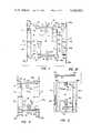
- FIG. 1is an exploded front elevation of a housing in accordance with the present invention
- FIG. 2is a front elevation of the housing of FIG. 1 with the components assembled
- FIG. 3is a bottom plan view of the assembled housing of FIG. 2;
- FIG. 4is a side elevation of the back end wall unit of the structure of FIGS. 1-3;
- FIG. 5is an end elevation of the back and end wall unit of FIG. 4;
- FIG. 6is an inside side elevation of a side wall unit of the structure of FIGS. 1-3;
- FIG. 7is an end view of the side wall unit of FIG. 6;
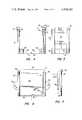
- FIG. 8is a front elevation of a housing in accordance with the invention showing the use of plural back and end wall units
- FIG. 9is an enlarged exploded partial front elevation of interlocking elements usable in the structure of FIGS. 1-8;
- FIG. 10is a partial sectional view along line 10--10 of FIG. 1.
- FIG. 1shows an exploded view of a housing constructed in accordance with the present invention, the housing illustrated being a "single" size housing.
- the housingincludes a central body, which is also shown by itself in FIGS. 4 and 5, indicated generally at 10 and two side wall bodies indicated generally at 11 and 12, one of which is separately shown in FIGS. 6 and 7.
- the central bodyincludes a back or rear wall 14 which is substantially planar and end walls 15 and 16, the major portions of which are planar, the end walls extending substantially perpendicularly from back wall 14 and in the same direction.
- this housingis primarily intended to receive a wall switch or outlet, or similar electrical device, and the front of the housing is therefore open.
- End walls 15 and 16are provided with thickened portions 17 and 18, respectively, having holes 19 and 20, respectively, to receive threaded fasteners for installation of the electrical device.
- End wall 15is provided with male and female coupling members indicated generally at 22 and 23, respectively.
- the male coupling memberincludes an elongated column 24, and the female coupling structure includes means defining an elongated recess 25 which is designed and dimensioned to receive and engage a male coupling column similar to 24.
- a stop block 26At one end of member 24 is a stop block 26 intended to inhibit longitudinal relative movement between the male member and a female coupling in one direction.
- end wall 16includes a male coupling member indicated generally at 30 extending along one edge of the wall and a female coupling member 31 along the other edge of the wall.
- male member 30is substantially identical to male member 22, and female member 31 is identical to member 23, but these members are provided at oppositely directed edges of the end members, i.e., the female members 23 and 31 open in opposite directions.
- Back wall 14although generally planar, is provided with a locking tab arrangement at opposite edges thereof.
- each side edge of wall 14is provided with a rectangular notch or recess, recess 34 being provided in the edge between coupling members 23 and 30, and recess 35 being provided between coupling members 22 and 31.
- These notchesoccupy approximately one half of the longitudinal dimension of the side edges, and the notches are covered, in the view of FIG. 1, by relatively short rectangular wall portions 36 and 37, respectively.
- These wall portionsare parallel with wall 14 and are of the same thickness as wall 14 but lie in planes slightly offset from the plane of wall 14.
- bosses 39 and 40Extending inwardly from end walls 15 and 16 and from back wall 14 are bosses 39 and 40 which have openings to receive mounting screws for mounting cable clamps.
- the outline of one such clamp 32 with its retaining screw 32ais shown in dash-dot lines in FIGS. 2 and 3, but it will be recognized that the clamp itself does not constitute part of the present invention.
- central body 10which have been described are integrally and unitarily formed as a single body, the body conveniently being molded as a single unit from a polymeric material such as polyvinyl chloride or the like.
- Side walls 11 and 12are identical to each other, and this identity will be recognized by realizing that rotation of either wall about a central axis 42, extending perpendicular to the plane of the drawing, through an angle of 180° will place one in the orientation of the other, and the components thereof will be the same. This is a particularly important factor, because it permits the entire housing, and housings of a number of different widths, to be produced using only two differently shaped components, one or more components shaped like central body 10 and two or more components shaped like side walls 11 and 12. Side wall 11 will be discussed in some detail, and the same components of side wall 12 will be identified by the same reference numerals followed by the letter "a".
- Wall 11includes a generally planar wall portion 44 having end tabs 45 and 46 centrally located at the upper end lower ends thereof with holes therethrough for mounting the assembled housing.
- a male coupling member 47Adjacent the rear edge of portion 44 is a relatively short wall 50 which extends almost to the mid-point of portion 44, the rear surface of wall 50 being in the same plane as the rear edge of portion 44.
- a similar wall 51occupies the remainder of the rear portion of the side wall, but wall 51 is offset toward the front edge of the side wall by a distance equal to the thickness of wall 50.
- walls 50 and 51form locking tabs which are capable of cooperating with tab 37 and the adjacent edge portion of wall 14 to prevent relative movement of the components, when assembled, in a direction perpendicular to the plane of the drawing.
- FIG. 6shows axis 42 about which the side member is rotated to reverse its position from a "left" side orientation to a “right” side orientation.
- block-like members 54formed on the inner surface of wall 51 and as part of tabs 36 and 37. These are support blocks which may be hollow and which are provided to strengthen the walls, and provide supports for the cable clamps.
- FIG. 2shows the elements of FIG. 1 fully assembled into a housing.
- the same reference numeralsare used, and it will be readily apparent that the components interlock to form a five-sided housing, the only openings other than the open front, as seen in FIG. 3, being openings 38 which can be formed by the punch-outs, as described in end wall 16 and, as seen in FIG. 5, openings 38 in end wall 15 to permit wires to be inserted for connection to the electrical device within the housing.
- FIG. 8illustrates the manner in which a housing can be formed having a greater volume and using exactly the same components as initially discussed in connection with FIG. 1.
- the assembly of FIG. 8includes central body 10 and side walls 11 and 12, and also includes a second central body 60 which is identical in every respect to body 10.
- the components of body 60are identified by the same reference numerals used in connection with body 10 but with the addition of the letter "b".
- housingscapable, for example, of receiving one, two, three or more switch units, outlet units or other electrical devices.
- FIG. 9illustrates in somewhat greater detail the configuration of the male and female coupling members, this diagram being applicable to any such pair of members on central or wall units.
- a female coupling member indicated generally at 65is attached to a wall 66 which can, for example, be the wall of a side member analogous to wall 44.
- the female coupling memberis elongated in a direction perpendicular to the plane of the drawing and has two parallel arms 67 and 68 extending perpendicular to wall 66.
- At the distal end of arms 67 and 68are inwardly directed hook members 69 and 70, respectively, forming a somewhat rectangular C-shaped opening.
- Arms 67 and 68are formed from a polymeric material, as is the rest of the structure, such as polyvinyl chloride which is relatively stiff but has sufficient resilence to permit the arms to be temporarily bent outwardly away from each other.
- the male coupling member 71which is used in conjunction therewith, and which can be, for example, along the edge of an end wall 72 analogous to walls 15 or 16, has a rounded end portion 73 which is substantially semi-circular in cross section. This portion merges smoothly into straight, parallel side portions 74 and 75 which terminate at shoulders 76 and 77 extending inwardly to wall 72.
- arms 67 and 68bend outwardly to permit the rounded end portion to pass between hooks 69 and 70, and after full insertion the hooks snap back to engage shoulders 76 and 77 to prevent withdrawal except upon the application of sufficient force to again bend the legs outwardly and overcome the hooking retention.
- these memberscan be disassembled and reassembled, they are not intended for repeated removal and insertion. Thus, they are intentionally formed so that significant force is required to disassemble a box once it has been fully assembled and put into use.
Landscapes
- Engineering & Computer Science (AREA)
- Architecture (AREA)
- Civil Engineering (AREA)
- Structural Engineering (AREA)
- Connector Housings Or Holding Contact Members (AREA)
Abstract
Description
Claims (16)
Priority Applications (1)
| Application Number | Priority Date | Filing Date | Title |
|---|---|---|---|
| US06/355,769US4428492A (en) | 1982-03-08 | 1982-03-08 | Gangable housing |
Applications Claiming Priority (1)
| Application Number | Priority Date | Filing Date | Title |
|---|---|---|---|
| US06/355,769US4428492A (en) | 1982-03-08 | 1982-03-08 | Gangable housing |
Publications (1)
| Publication Number | Publication Date |
|---|---|
| US4428492Atrue US4428492A (en) | 1984-01-31 |
Family
ID=23398769
Family Applications (1)
| Application Number | Title | Priority Date | Filing Date |
|---|---|---|---|
| US06/355,769Expired - LifetimeUS4428492A (en) | 1982-03-08 | 1982-03-08 | Gangable housing |
Country Status (1)
| Country | Link |
|---|---|
| US (1) | US4428492A (en) |
Cited By (46)
| Publication number | Priority date | Publication date | Assignee | Title |
|---|---|---|---|---|
| US5347088A (en)* | 1992-09-22 | 1994-09-13 | Tenn-Tex Plastics, Inc. | Electrical junction box |
| US5378854A (en)* | 1993-04-12 | 1995-01-03 | Hoover; Daniel M. | Electrical outlet box assembly |
| EP0654880A1 (en)* | 1993-11-19 | 1995-05-24 | Johnson Service Company | Modular wall-mounted equipment enclosure |
| US5471012A (en)* | 1994-07-28 | 1995-11-28 | Geo Ventures | Electrical wire box apparatus |
| US5509560A (en)* | 1995-06-01 | 1996-04-23 | Nash; William L. | Gangable plastic box for electrical outlets |
| US5574255A (en)* | 1993-06-14 | 1996-11-12 | Simmons; Micheal L. | Laterally expandable modular electrical box |
| FR2737055A1 (en)* | 1995-07-19 | 1997-01-24 | Legrand Sa | Housing for attaching electrical equipment to surface - has base moulded with flat bottom and two opposite side walls, with other two walls sliding into place between these walls, and has hollow square fitting in top to hold electrical equipment |
| US5619013A (en)* | 1993-12-17 | 1997-04-08 | Hubbell Incorporated | Gangable electrical box |
| US5679924A (en)* | 1995-06-07 | 1997-10-21 | Walker Systems, Inc. | Non-metallic floor box |
| US5700978A (en)* | 1996-01-25 | 1997-12-23 | Pass & Seymour, Inc. | Snap-together wall plates for ganged electrical device installations |
| US5783774A (en)* | 1996-10-21 | 1998-07-21 | Walker Systems, Inc. | Non-metallic floor box |
| US5866845A (en)* | 1997-06-02 | 1999-02-02 | The Lamson & Sessions Co. | Electrical box |
| AT405994B (en)* | 1994-11-11 | 2000-01-25 | Kontavill Kontakta Villamossze | Electrical service apparatus for flush mounting |
| FR2781616A1 (en)* | 1998-07-24 | 2000-01-28 | Legrand Sa | Electrical equipment box that can be placed in tandem with another box, with removable panels of different widths |
| US6057509A (en)* | 1993-06-14 | 2000-05-02 | Simmons; Michael L. | Modularized electrical box systems |
| US6229087B1 (en) | 1999-08-17 | 2001-05-08 | Thomas & Betts International, Inc. | Gangable electrical box |
| US6259023B1 (en) | 1999-06-28 | 2001-07-10 | Reiker Electric, L.L.C. | Electrical outlet box |
| US6278058B1 (en)* | 1998-03-11 | 2001-08-21 | Rebecca J. Anderson | Electrical box and box assembly |
| EP1209785A1 (en)* | 2000-11-24 | 2002-05-29 | Ensto Busch-Jaeger Oy | Mounting box for wiring accessories |
| US20020162680A1 (en)* | 1999-06-28 | 2002-11-07 | Reiker Kenneth H. | Dual-purpose wiring device and method of wiring |
| US6585486B2 (en) | 2001-07-12 | 2003-07-01 | Honeywell International Inc. | Electrical appliance enclosure with removable side wall |
| EP1365492A1 (en)* | 2002-05-24 | 2003-11-26 | JVK Plastics, naamloze vennootschap | Built-in housing for electrical equipment |
| US20040074659A1 (en)* | 2001-09-05 | 2004-04-22 | Roesch Mark A. | Gangable electrical unit |
| US20050056450A1 (en)* | 2003-09-15 | 2005-03-17 | Hull Eric G. | Electrical bracket |
| US20050092509A1 (en)* | 2003-11-05 | 2005-05-05 | Thomas & Betts International, Inc. | Gangable electrical box |
| US20060076348A1 (en)* | 2004-10-12 | 2006-04-13 | Thomas & Betts International, Inc. | Electrical outlet box having attachable walls |
| US20070120029A1 (en)* | 2005-11-29 | 2007-05-31 | Rgb Systems, Inc. | A Modular Wall Mounting Apparatus |
| US20080083551A1 (en)* | 2006-10-05 | 2008-04-10 | Drue Schlachter | Electrical switch box |
| US7357541B2 (en) | 2004-04-05 | 2008-04-15 | Genlyte Thomas Group, Llc | Enclosure for socket cup for snap-in electrical quick connectors |
| US20100025064A1 (en)* | 2008-08-04 | 2010-02-04 | James M. Nelson, III | Sectional Electrical Boxes |
| US20100319986A1 (en)* | 2009-06-17 | 2010-12-23 | Bleau Charles A | Modular vented circuit board enclosure |
| FR2952478A1 (en)* | 2009-11-12 | 2011-05-13 | Ensto Ind | Plug block, has plug block sub assemblies connected with respect to each other by insulated connection wall that is equipped with connecting projections for covering ending of electric cables in positioning groove |
| US20110188254A1 (en)* | 2010-01-30 | 2011-08-04 | Koninklijke Philips Electronics N.V. | Recessed Fixture Housing Having Removable Ballast Box |
| US7993037B1 (en) | 2008-08-27 | 2011-08-09 | Koninklijke Philips Electronics N.V. | Recessed light fixture with a movable junction box |
| US20110259635A1 (en)* | 2010-04-27 | 2011-10-27 | Leviton Manufacturing Co., Inc. | Electrical device alignment system |
| US8212144B1 (en)* | 2010-01-27 | 2012-07-03 | Arlington Industries, Inc. | Gangable modular electrical box assembly with interlocking modules |
| US8420956B2 (en) | 2010-04-27 | 2013-04-16 | Leviton Manufacturing Co., Inc. | Electrical device mounting adapter |
| US8669471B2 (en) | 2010-09-14 | 2014-03-11 | Southwire Company | Electrical accessories and associated methods of use and manufacture |
| US8680407B1 (en)* | 2012-10-04 | 2014-03-25 | Vpl Enterprises Ltd. | Modular enclosure assembly for terminals wiring and distribution |
| US8789256B2 (en) | 2010-09-14 | 2014-07-29 | Southwire Company, Llc | Folded electrical junction boxes and associated methods of use and manufacture |
| US9553433B2 (en)* | 2014-04-29 | 2017-01-24 | Thomas & Betts International Llc | Snap-in gangable electrical box |
| US9819167B2 (en) | 2009-09-04 | 2017-11-14 | Cantex, Inc. | Electrical accessories and associated methods of use and manufacture |
| US20190289741A1 (en)* | 2018-03-16 | 2019-09-19 | Yazaki Corporation | Electrical junction box |
| US10683645B2 (en) | 2017-03-23 | 2020-06-16 | Oatey Co. | Modular plumbing box system and methods of mounting the same |
| US11271380B2 (en)* | 2018-11-07 | 2022-03-08 | Patrick Michael LLOYD | Temporary electrical box covers |
| US20230290585A1 (en)* | 2018-01-19 | 2023-09-14 | Lutron Technology Company Llc | Wall Box Providing Adjustable Support for a Control Device |
Citations (23)
| Publication number | Priority date | Publication date | Assignee | Title |
|---|---|---|---|---|
| US1326498A (en) | 1917-01-12 | 1919-12-30 | Don H Hayden | Switch-box or outlet-box. |
| US1531542A (en) | 1924-02-21 | 1925-03-31 | Morry L Cogshall | Toy block |
| US1817307A (en) | 1930-01-02 | 1931-08-04 | Art Concrete Works | Extensible meter box |
| US2552400A (en) | 1948-08-02 | 1951-05-08 | William F Brunia | Sectional metal box |
| US2751105A (en) | 1954-03-22 | 1956-06-19 | Robert B Eipper | Outlet box for wiring circuits |
| DE965155C (en) | 1954-02-12 | 1957-06-06 | Georges Livas | Suppository holder made of plastic material, formed from detachable elements connected to a chain and usable for forming suppositories |
| US2867349A (en) | 1953-10-01 | 1959-01-06 | Union Insulating Co Inc | Molded plastic articles such as outlet boxes |
| GB808492A (en) | 1954-08-09 | 1959-02-04 | Mac Echern & Company Ltd | Improvements in or relating to collapsible cases or boxes |
| US3168613A (en) | 1963-05-08 | 1965-02-02 | Union Insulating Co | Insulated wiring box made of selectively useable molded sections of thermoplastic material united by solvent welding to form a unitary box |
| NL6516181A (en) | 1965-02-17 | 1966-08-18 | ||
| US3283062A (en) | 1965-08-31 | 1966-11-01 | Gen Electric | Terminal enclosure |
| US3299199A (en) | 1964-02-20 | 1967-01-17 | Cadre Ind Corp | Terminal box |
| US3317073A (en) | 1965-01-06 | 1967-05-02 | Schick Electric Inc | Plastic molded case halves with concealed interlock |
| US3622029A (en) | 1969-05-12 | 1971-11-23 | Ware Fuse Corp | Electrical outlet box |
| US3728470A (en) | 1971-09-27 | 1973-04-17 | W Maier | Electrical outlet box with cable connectors |
| US3840140A (en) | 1972-08-31 | 1974-10-08 | C Tisbo | Cable closure |
| US3863037A (en) | 1970-09-03 | 1975-01-28 | Nelco Corp | Electrical box hanger structure |
| US3873759A (en) | 1972-06-22 | 1975-03-25 | Nelco Corp | Electrical enclosure knockout structure |
| US3999676A (en) | 1975-02-28 | 1976-12-28 | Litco Plastics Co. | Collapsible container |
| US4062470A (en) | 1976-08-04 | 1977-12-13 | Slater Electric Inc. | Electrical outlet box mounting assembly |
| US4202457A (en) | 1978-08-25 | 1980-05-13 | Eagle Electric Mgf. Co., Inc. | Foldable electrical outlet box |
| US4214668A (en) | 1979-02-21 | 1980-07-29 | Indian Head Inc. | Electrical box and mounting bracket assembly |
| US4265365A (en) | 1978-04-28 | 1981-05-05 | Slater Electric Inc. | Moisture resistant electrical outlet box |
- 1982
- 1982-03-08USUS06/355,769patent/US4428492A/ennot_activeExpired - Lifetime
Patent Citations (23)
| Publication number | Priority date | Publication date | Assignee | Title |
|---|---|---|---|---|
| US1326498A (en) | 1917-01-12 | 1919-12-30 | Don H Hayden | Switch-box or outlet-box. |
| US1531542A (en) | 1924-02-21 | 1925-03-31 | Morry L Cogshall | Toy block |
| US1817307A (en) | 1930-01-02 | 1931-08-04 | Art Concrete Works | Extensible meter box |
| US2552400A (en) | 1948-08-02 | 1951-05-08 | William F Brunia | Sectional metal box |
| US2867349A (en) | 1953-10-01 | 1959-01-06 | Union Insulating Co Inc | Molded plastic articles such as outlet boxes |
| DE965155C (en) | 1954-02-12 | 1957-06-06 | Georges Livas | Suppository holder made of plastic material, formed from detachable elements connected to a chain and usable for forming suppositories |
| US2751105A (en) | 1954-03-22 | 1956-06-19 | Robert B Eipper | Outlet box for wiring circuits |
| GB808492A (en) | 1954-08-09 | 1959-02-04 | Mac Echern & Company Ltd | Improvements in or relating to collapsible cases or boxes |
| US3168613A (en) | 1963-05-08 | 1965-02-02 | Union Insulating Co | Insulated wiring box made of selectively useable molded sections of thermoplastic material united by solvent welding to form a unitary box |
| US3299199A (en) | 1964-02-20 | 1967-01-17 | Cadre Ind Corp | Terminal box |
| US3317073A (en) | 1965-01-06 | 1967-05-02 | Schick Electric Inc | Plastic molded case halves with concealed interlock |
| NL6516181A (en) | 1965-02-17 | 1966-08-18 | ||
| US3283062A (en) | 1965-08-31 | 1966-11-01 | Gen Electric | Terminal enclosure |
| US3622029A (en) | 1969-05-12 | 1971-11-23 | Ware Fuse Corp | Electrical outlet box |
| US3863037A (en) | 1970-09-03 | 1975-01-28 | Nelco Corp | Electrical box hanger structure |
| US3728470A (en) | 1971-09-27 | 1973-04-17 | W Maier | Electrical outlet box with cable connectors |
| US3873759A (en) | 1972-06-22 | 1975-03-25 | Nelco Corp | Electrical enclosure knockout structure |
| US3840140A (en) | 1972-08-31 | 1974-10-08 | C Tisbo | Cable closure |
| US3999676A (en) | 1975-02-28 | 1976-12-28 | Litco Plastics Co. | Collapsible container |
| US4062470A (en) | 1976-08-04 | 1977-12-13 | Slater Electric Inc. | Electrical outlet box mounting assembly |
| US4265365A (en) | 1978-04-28 | 1981-05-05 | Slater Electric Inc. | Moisture resistant electrical outlet box |
| US4202457A (en) | 1978-08-25 | 1980-05-13 | Eagle Electric Mgf. Co., Inc. | Foldable electrical outlet box |
| US4214668A (en) | 1979-02-21 | 1980-07-29 | Indian Head Inc. | Electrical box and mounting bracket assembly |
Cited By (67)
| Publication number | Priority date | Publication date | Assignee | Title |
|---|---|---|---|---|
| US5347088A (en)* | 1992-09-22 | 1994-09-13 | Tenn-Tex Plastics, Inc. | Electrical junction box |
| US5378854A (en)* | 1993-04-12 | 1995-01-03 | Hoover; Daniel M. | Electrical outlet box assembly |
| US5574255A (en)* | 1993-06-14 | 1996-11-12 | Simmons; Micheal L. | Laterally expandable modular electrical box |
| US6057509A (en)* | 1993-06-14 | 2000-05-02 | Simmons; Michael L. | Modularized electrical box systems |
| US5874692A (en)* | 1993-06-14 | 1999-02-23 | Jeffrey S. Houk | Laterally expandable modular electrical box and method of reducing wiring time and mounting wall disfiguration |
| EP0654880A1 (en)* | 1993-11-19 | 1995-05-24 | Johnson Service Company | Modular wall-mounted equipment enclosure |
| US5703327A (en)* | 1993-12-17 | 1997-12-30 | Hubbell Incorporated | Electrical boxes |
| US5619013A (en)* | 1993-12-17 | 1997-04-08 | Hubbell Incorporated | Gangable electrical box |
| US5471012A (en)* | 1994-07-28 | 1995-11-28 | Geo Ventures | Electrical wire box apparatus |
| AT405994B (en)* | 1994-11-11 | 2000-01-25 | Kontavill Kontakta Villamossze | Electrical service apparatus for flush mounting |
| US5509560A (en)* | 1995-06-01 | 1996-04-23 | Nash; William L. | Gangable plastic box for electrical outlets |
| US5679924A (en)* | 1995-06-07 | 1997-10-21 | Walker Systems, Inc. | Non-metallic floor box |
| US6096972A (en)* | 1995-06-07 | 2000-08-01 | Walker Systems, Inc. | Non-metallic floor box |
| FR2737055A1 (en)* | 1995-07-19 | 1997-01-24 | Legrand Sa | Housing for attaching electrical equipment to surface - has base moulded with flat bottom and two opposite side walls, with other two walls sliding into place between these walls, and has hollow square fitting in top to hold electrical equipment |
| US5700978A (en)* | 1996-01-25 | 1997-12-23 | Pass & Seymour, Inc. | Snap-together wall plates for ganged electrical device installations |
| US5783774A (en)* | 1996-10-21 | 1998-07-21 | Walker Systems, Inc. | Non-metallic floor box |
| US5866845A (en)* | 1997-06-02 | 1999-02-02 | The Lamson & Sessions Co. | Electrical box |
| US6278058B1 (en)* | 1998-03-11 | 2001-08-21 | Rebecca J. Anderson | Electrical box and box assembly |
| FR2781616A1 (en)* | 1998-07-24 | 2000-01-28 | Legrand Sa | Electrical equipment box that can be placed in tandem with another box, with removable panels of different widths |
| BE1013053A3 (en)* | 1998-07-24 | 2001-08-07 | Legrand Sa | Box built may be detached with another, particularly for electrical equipment. |
| US6730844B2 (en) | 1999-06-28 | 2004-05-04 | Kenneth H Reiker | Dual-purpose wiring device and method of wiring |
| US6259023B1 (en) | 1999-06-28 | 2001-07-10 | Reiker Electric, L.L.C. | Electrical outlet box |
| US20020162680A1 (en)* | 1999-06-28 | 2002-11-07 | Reiker Kenneth H. | Dual-purpose wiring device and method of wiring |
| US6229087B1 (en) | 1999-08-17 | 2001-05-08 | Thomas & Betts International, Inc. | Gangable electrical box |
| EP1209785A1 (en)* | 2000-11-24 | 2002-05-29 | Ensto Busch-Jaeger Oy | Mounting box for wiring accessories |
| US6585486B2 (en) | 2001-07-12 | 2003-07-01 | Honeywell International Inc. | Electrical appliance enclosure with removable side wall |
| US20040074659A1 (en)* | 2001-09-05 | 2004-04-22 | Roesch Mark A. | Gangable electrical unit |
| US6872884B2 (en)* | 2001-09-05 | 2005-03-29 | The Lamson & Sessions Co. | Gangable electrical unit |
| BE1015451A3 (en)* | 2002-05-24 | 2005-04-05 | Jvk Plastics Nv | Installation box for electrical components. |
| EP1365492A1 (en)* | 2002-05-24 | 2003-11-26 | JVK Plastics, naamloze vennootschap | Built-in housing for electrical equipment |
| US6870101B1 (en) | 2003-09-15 | 2005-03-22 | The Lamson & Sessions Co. | Electrical bracket |
| US20050056450A1 (en)* | 2003-09-15 | 2005-03-17 | Hull Eric G. | Electrical bracket |
| US20050144891A1 (en)* | 2003-09-15 | 2005-07-07 | Hull Eric G. | Electrical bracket |
| US6940017B2 (en) | 2003-09-15 | 2005-09-06 | The Lamson & Sessions Co. | Breakaway member |
| US7112743B2 (en) | 2003-09-15 | 2006-09-26 | The Lamson & Sessions Co. | Electrical bracket |
| US20050056449A1 (en)* | 2003-09-15 | 2005-03-17 | Roesch Mark A. | Breakaway member |
| US20050092509A1 (en)* | 2003-11-05 | 2005-05-05 | Thomas & Betts International, Inc. | Gangable electrical box |
| US6903272B2 (en) | 2003-11-05 | 2005-06-07 | Thomas & Betts International, Inc. | Gangable electrical box |
| US7357541B2 (en) | 2004-04-05 | 2008-04-15 | Genlyte Thomas Group, Llc | Enclosure for socket cup for snap-in electrical quick connectors |
| US20060076348A1 (en)* | 2004-10-12 | 2006-04-13 | Thomas & Betts International, Inc. | Electrical outlet box having attachable walls |
| US20070120029A1 (en)* | 2005-11-29 | 2007-05-31 | Rgb Systems, Inc. | A Modular Wall Mounting Apparatus |
| US20080083551A1 (en)* | 2006-10-05 | 2008-04-10 | Drue Schlachter | Electrical switch box |
| US7659478B2 (en)* | 2006-10-05 | 2010-02-09 | Drue Schlachter | Electrical switch box |
| US20100132971A1 (en)* | 2006-10-05 | 2010-06-03 | Drue Schlachter | Electrical switch box |
| US20100025064A1 (en)* | 2008-08-04 | 2010-02-04 | James M. Nelson, III | Sectional Electrical Boxes |
| US8088998B2 (en) | 2008-08-04 | 2012-01-03 | Nelson James M | Sectional electrical boxes |
| US7993037B1 (en) | 2008-08-27 | 2011-08-09 | Koninklijke Philips Electronics N.V. | Recessed light fixture with a movable junction box |
| US20100319986A1 (en)* | 2009-06-17 | 2010-12-23 | Bleau Charles A | Modular vented circuit board enclosure |
| US9819167B2 (en) | 2009-09-04 | 2017-11-14 | Cantex, Inc. | Electrical accessories and associated methods of use and manufacture |
| FR2952478A1 (en)* | 2009-11-12 | 2011-05-13 | Ensto Ind | Plug block, has plug block sub assemblies connected with respect to each other by insulated connection wall that is equipped with connecting projections for covering ending of electric cables in positioning groove |
| US8212144B1 (en)* | 2010-01-27 | 2012-07-03 | Arlington Industries, Inc. | Gangable modular electrical box assembly with interlocking modules |
| US20110188254A1 (en)* | 2010-01-30 | 2011-08-04 | Koninklijke Philips Electronics N.V. | Recessed Fixture Housing Having Removable Ballast Box |
| US8465181B2 (en) | 2010-01-30 | 2013-06-18 | Koninklijke Philips Electronics N.V. | Recessed fixture housing having removable ballast box |
| US20110259635A1 (en)* | 2010-04-27 | 2011-10-27 | Leviton Manufacturing Co., Inc. | Electrical device alignment system |
| US8420956B2 (en) | 2010-04-27 | 2013-04-16 | Leviton Manufacturing Co., Inc. | Electrical device mounting adapter |
| US8669471B2 (en) | 2010-09-14 | 2014-03-11 | Southwire Company | Electrical accessories and associated methods of use and manufacture |
| US8789256B2 (en) | 2010-09-14 | 2014-07-29 | Southwire Company, Llc | Folded electrical junction boxes and associated methods of use and manufacture |
| US8680407B1 (en)* | 2012-10-04 | 2014-03-25 | Vpl Enterprises Ltd. | Modular enclosure assembly for terminals wiring and distribution |
| US9553433B2 (en)* | 2014-04-29 | 2017-01-24 | Thomas & Betts International Llc | Snap-in gangable electrical box |
| US10683645B2 (en) | 2017-03-23 | 2020-06-16 | Oatey Co. | Modular plumbing box system and methods of mounting the same |
| US11674292B2 (en) | 2017-03-23 | 2023-06-13 | Oatey Co. | Modular plumbing box system and methods of mounting the same |
| US12180691B2 (en) | 2017-03-23 | 2024-12-31 | Oatey Co. | Modular plumbing box system and methods of mounting the same |
| US20230290585A1 (en)* | 2018-01-19 | 2023-09-14 | Lutron Technology Company Llc | Wall Box Providing Adjustable Support for a Control Device |
| US12062507B2 (en)* | 2018-01-19 | 2024-08-13 | Lutron Technology Company Llc | Wall box providing adjustable support for a control device |
| US20190289741A1 (en)* | 2018-03-16 | 2019-09-19 | Yazaki Corporation | Electrical junction box |
| US10701827B2 (en)* | 2018-03-16 | 2020-06-30 | Yazaki Corporation | Electrical junction box with divided portions |
| US11271380B2 (en)* | 2018-11-07 | 2022-03-08 | Patrick Michael LLOYD | Temporary electrical box covers |
Similar Documents
| Publication | Publication Date | Title |
|---|---|---|
| US4428492A (en) | Gangable housing | |
| US4688747A (en) | Low voltage computer cable wall aperture molding | |
| US4210379A (en) | Modular barrier block | |
| US4293172A (en) | Case for electrical multiple outlet | |
| US4659162A (en) | Multiple contact connector casing and device for locking contact carrier in casing | |
| CA1301875C (en) | Floating panel mount for electrical connector | |
| US6118075A (en) | Stackable universal pitch cable trough system | |
| US5696350A (en) | Interchangeable sectional wallplates | |
| US4907767A (en) | Stackable modular duct assemblies | |
| USRE35344E (en) | Panel mountable electrical connector | |
| US5031083A (en) | Arrangement for open profile lengths | |
| US4952172A (en) | Electrical connector stiffener device | |
| AU710335B2 (en) | Connector mounting receptacles | |
| US7481406B2 (en) | Plastic pegboard assembly | |
| CA2013501C (en) | Stiffening arrangement for ducting for electrical conductors and the like and corresponding clamp | |
| US4012580A (en) | Electrical wiring box | |
| KR20190132681A (en) | Modular system for plug connector modules, plug connector units and modular housing frames for them | |
| US5055057A (en) | Electric plug lock | |
| US3273103A (en) | Polarizing means for busway plug | |
| US5035645A (en) | Bracket for terminal block | |
| CA2174393C (en) | Snap-together wall plates for ganged electrical device installations | |
| US4934962A (en) | Plug-in electrical outlet | |
| WO1980002587A1 (en) | Improvements in clamp members | |
| US5663527A (en) | Stackable conduits with hook and hole clip means | |
| US5839922A (en) | 110 wiring block interlock and interlocked blocks utilizing such |
Legal Events
| Date | Code | Title | Description |
|---|---|---|---|
| AS | Assignment | Owner name:HARVEY HUBBELL, INCORPORATED, NEW HAVEN, CT A CORP Free format text:ASSIGNMENT OF ASSIGNORS INTEREST.;ASSIGNOR:JORGENSEN, ROBERT W.;REEL/FRAME:003980/0813 Effective date:19820219 | |
| STCF | Information on status: patent grant | Free format text:PATENTED CASE | |
| MAFP | Maintenance fee payment | Free format text:PAYMENT OF MAINTENANCE FEE, 4TH YEAR, PL 96-517 (ORIGINAL EVENT CODE: M170); ENTITY STATUS OF PATENT OWNER: LARGE ENTITY Year of fee payment:4 | |
| AS | Assignment | Owner name:HUBBELL INCORPORATED Free format text:CHANGE OF NAME;ASSIGNOR:HARVEY HUBBELL, INCORPORATED;REEL/FRAME:004765/0634 Effective date:19870401 | |
| MAFP | Maintenance fee payment | Free format text:PAYMENT OF MAINTENANCE FEE, 8TH YEAR, PL 96-517 (ORIGINAL EVENT CODE: M171); ENTITY STATUS OF PATENT OWNER: LARGE ENTITY Year of fee payment:8 | |
| MAFP | Maintenance fee payment | Free format text:PAYMENT OF MAINTENANCE FEE, 12TH YEAR, LARGE ENTITY (ORIGINAL EVENT CODE: M185); ENTITY STATUS OF PATENT OWNER: LARGE ENTITY Year of fee payment:12 |