US4427378A - Closure and seal construction for high-pressure oxidation furnace and the like - Google Patents
Closure and seal construction for high-pressure oxidation furnace and the likeDownload PDFInfo
- Publication number
- US4427378A US4427378AUS06/363,062US36306282AUS4427378AUS 4427378 AUS4427378 AUS 4427378AUS 36306282 AUS36306282 AUS 36306282AUS 4427378 AUS4427378 AUS 4427378A
- Authority
- US
- United States
- Prior art keywords
- closure
- wall
- tube
- recess
- opening
- Prior art date
- Legal status (The legal status is an assumption and is not a legal conclusion. Google has not performed a legal analysis and makes no representation as to the accuracy of the status listed.)
- Expired - Lifetime
Links
- 230000003647oxidationEffects0.000titleclaimsabstractdescription9
- 238000007254oxidation reactionMethods0.000titleclaimsabstractdescription9
- 238000010276constructionMethods0.000titleclaimsabstractdescription6
- VYPSYNLAJGMNEJ-UHFFFAOYSA-Nsilicon dioxideInorganic materialsO=[Si]=OVYPSYNLAJGMNEJ-UHFFFAOYSA-N0.000claimsabstractdescription16
- 239000010453quartzSubstances0.000claimsabstractdescription15
- 238000007789sealingMethods0.000claimsabstractdescription7
- 239000000463materialSubstances0.000claimsabstractdescription5
- 239000011248coating agentSubstances0.000claimsdescription9
- 238000000576coating methodMethods0.000claimsdescription9
- 239000002826coolantSubstances0.000claimsdescription6
- 230000000694effectsEffects0.000claimsdescription3
- 238000001816coolingMethods0.000abstractdescription5
- 229910001220stainless steelInorganic materials0.000description10
- 239000010935stainless steelSubstances0.000description10
- XLYOFNOQVPJJNP-UHFFFAOYSA-NwaterSubstancesOXLYOFNOQVPJJNP-UHFFFAOYSA-N0.000description5
- 238000000034methodMethods0.000description4
- 235000012431wafersNutrition0.000description4
- 238000006243chemical reactionMethods0.000description3
- 230000006835compressionEffects0.000description3
- 238000007906compressionMethods0.000description3
- 238000011109contaminationMethods0.000description3
- 239000007789gasSubstances0.000description3
- 239000002184metalSubstances0.000description3
- 238000010943off-gassingMethods0.000description3
- 229920001296polysiloxanePolymers0.000description3
- 229920002379silicone rubberPolymers0.000description2
- XUIMIQQOPSSXEZ-UHFFFAOYSA-NSiliconChemical compound[Si]XUIMIQQOPSSXEZ-UHFFFAOYSA-N0.000description1
- 230000015556catabolic processEffects0.000description1
- 238000005229chemical vapour depositionMethods0.000description1
- 239000002131composite materialSubstances0.000description1
- 238000006731degradation reactionMethods0.000description1
- 230000009977dual effectEffects0.000description1
- 230000008030eliminationEffects0.000description1
- 238000003379elimination reactionMethods0.000description1
- 230000007717exclusionEffects0.000description1
- 239000005350fused silica glassSubstances0.000description1
- 238000010438heat treatmentMethods0.000description1
- 238000004519manufacturing processMethods0.000description1
- 230000036316preloadEffects0.000description1
- 238000005096rolling processMethods0.000description1
- 229910052710siliconInorganic materials0.000description1
- 239000010703siliconSubstances0.000description1
- 239000004945silicone rubberSubstances0.000description1
- 239000000126substanceSubstances0.000description1
- 238000003466weldingMethods0.000description1
Images

Classifications
- F—MECHANICAL ENGINEERING; LIGHTING; HEATING; WEAPONS; BLASTING
- F26—DRYING
- F26B—DRYING SOLID MATERIALS OR OBJECTS BY REMOVING LIQUID THEREFROM
- F26B25/00—Details of general application not covered by group F26B21/00 or F26B23/00
- F26B25/06—Chambers, containers, or receptacles
- F26B25/08—Parts thereof
- F26B25/12—Walls or sides; Doors
- F—MECHANICAL ENGINEERING; LIGHTING; HEATING; WEAPONS; BLASTING
- F27—FURNACES; KILNS; OVENS; RETORTS
- F27B—FURNACES, KILNS, OVENS OR RETORTS IN GENERAL; OPEN SINTERING OR LIKE APPARATUS
- F27B17/00—Furnaces of a kind not covered by any of groups F27B1/00 - F27B15/00
- F—MECHANICAL ENGINEERING; LIGHTING; HEATING; WEAPONS; BLASTING
- F27—FURNACES; KILNS; OVENS; RETORTS
- F27D—DETAILS OR ACCESSORIES OF FURNACES, KILNS, OVENS OR RETORTS, IN SO FAR AS THEY ARE OF KINDS OCCURRING IN MORE THAN ONE KIND OF FURNACE
- F27D1/00—Casings; Linings; Walls; Roofs
- F27D1/18—Door frames; Doors, lids or removable covers
Definitions
- the inventionrelates to apparatus used for the processing of silicon wafers, such as high pressure oxidation and chemical vapor deposition furnaces, and the like, for example see U.S. Pat. No. 4,167,915.
- furnaces of the character describedusually perform their processing activities within a quartz chamber, typically an open ended quartz cylinder. These furnaces also typically use a stainless steel end cap arrangement to provide for inserting and removing the wafer load into and from the furnace chamber and to provide the necessary gas tight seal required for exclusion of air and containment of process gases. Sealing of the end caps is normally accomplished by means of an elastomeric seal, such as an O-ring or gasket, to seal a stainless steel assembly to a quartz flange fused to the end of a furnace tube. A further O-ring is commonly used to obtain a seal between a stainless steel door plate and a stainless steel flange, with the door plate being moveable to provide the necessary access to the interior of the furnace chamber.
- an elastomeric sealsuch as an O-ring or gasket
- An object of the present inventionis to provide in a furnace of the character described a closure and seal construction which may be simply and readily manufactured at modest cost; which will provide a highly effective seal; and will at the same time fully protect the work being processed against contaminating out-gassing of elastomeric and structural members forming the closure and seal.
- Another feature of the present inventionis the elimination of all exposed metal parts in areas where their heating and out-gassing will produce contamination.
- Still another and important feature of the present inventionis the obtaining of water cooling of critical, engaged, quartz parts, which has heretofore been most difficult to obtain although a much sought after objective.
- FIG. 1is a fragmentary prospective view of a closure and seal construction for a high pressure oxidation furnace and the like, constructed in accordance with the present invention.
- FIG. 2is a view similar to FIG. 1 but showing the parts in a different position.
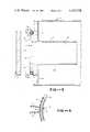
- FIG. 3is an enlarged fragmentary cross-sectional view of a portion of the structure with parts of the closing mechanism removed.
- FIG. 4is a front elevation of a portion of the structure taken substantially on the plane of line 4--4 of FIG. 3.
- FIG. 5is a fragmentary cross-sectional view on a further enlarged scale of a portion of the device indicated by line 5--5 of FIG. 4.
- the closure and seal construction of the present inventionis particularly adapted for use on a high pressure oxidation furnace 11 of the type generally illustrated and described in U.S. Pat. No. 4,167,915 and which has as one of its principal components a cylinderical quartz tube 12 providing a quartz chamber 13 within which silicone wafers are processed by well-known techniques in the production of integrated circuits on silicone chips. Quartz tube 12 is mounted within a pressure chamber 15 permitting equalization, or at least reduction to an acceptable amount, of a pressure differential across the rather fragile wall of the tube. Typically the external pressure chamber 15 is maintained at a pressure of about one atmosphere greater than the interior pressure in chamber 13. For other structural and functional details of the furnace, reference is made to U.S. Pat. No. 4,167,915.
- Opening 14must be closed for carrying out the high pressure oxidation process, and the present invention is concerned with the structure for effecting such closure.
- quartz tube 12is formed with an integral end wall or flange 16 providing a flat annular surface 17 surrounding opening 14, and surface 17 is formed with an annular recess 18.
- a coolant and sealing tube 19is mounted in recess 18 and has a diameter causing the tube to protrude slightly from surface 17 by a small distance noted by dimension d in FIG. 3.
- Tube 19is provided with inlet and outlet connections 36 and 37 adapted for connection to a source of coolant and for conduction of coolant through the tube.
- closure plate 21Mounted for movement to and from surface 17 and tube 19 is closure plate 21 which in its closed position effects a covering and closing of opening 14.
- a closing pressureis applied to plate 21 which cofunctions with the elasticity of tube 19 causing the latter to resiliently retract and provide simultaneous sealing engagement of the interior surface 22 of the closure with surface 17 and tube 19.
- An operating pressuremay be obtained in part from the mounting means 23 for the closure and in part by the pressure differential across the closure applied by the relatively higher pressure in the surrounding pressure chamber.
- tube 19is formed as a composite or laiminated structure with an interior metal tube 26, such as stainless steel to provide thermal conductivity, and an elastomeric coating 27 such as silicone rubber.
- the finished cross-section diameter of the O-ring thus formedis chosen to be about 0.012 inches to 0.018 inches larger than the depth of recess 18, measured axially of tube 12.
- surface 17 and wall 16are provided by a quartz flange welded or fused to the end of quartz tube 12; the flange being formed around its periphery and at surface 17 with recess 18; and the annular surface 17 interiorally of the recess is ground flat and optically polished.
- door plate 21is made of clear fused quartz and also has its interior surface 22 ground flat and optically polished so as to provide a sealed contact with surface 17.
- the O-ring tube 19may be conveniently formed by rolling the metal tube 26 in a circle and welding the opposite ends 31 and 32 of the tube to a divider disc 33, see FIG. 5.
- Inlet an outlet tubes 36 and 37are here welded on each side of divider 33 to provide water coolant circulation as above noted.
- any suitable mounting and actuation structuremay be used for juxtaposing closure 21 to annular surface 17 and tube 19 in covering relation to opening 14 and to apply at least an initial closing pressure urging closure 21 toward surface 17 and tube 19.
- an end plate 41 adjacent flange 16carries a hinged joint 42 for one end of an arm 43 having its opposite end connected a hinged joint 44 which is secured to a plate 46 fastened, as by fingers 48, to the exterior side 47 of closure 21, the hinged structure thus formed providing for the swinging of closure plate 21 from an open position as illustrated in FIG. 2 to a closed position across the end of the tube as illustrated in FIG. 1.
- Opening and closing of the closure plateis preferably effected by automated means 51 which is at the same time capable of supplying a requisite closing force.
- motorized actuationis obtained by a hydraulic or pneumatic cylinder 51 secured at one end 52 to mounting plate 41 and having a piston driven shaft 53 at its opposite end connected to a bracket 54 having a swivel mounting on arm 43. Accordingly extension of shaft 53, as seen in FIG. 2 will cause closure plate 21 to open, and retraction of shaft 53 into cylinder 51 will cause the closure plate to swing into abutment with the flange surface 17 and ring 19.
- the closure mechanismis capable of producing a closing force on closure plate 21 in the order of about 25 to 75 pounds.
- the exterior pressure chamberwill maintain a pressure differential across the closure door of approximately one atmosphere which, in a typical size furnace having a 135 mm furnace tube, will place an end thrust of approxmately 325 pounds on the door plate 21.
- the combination of 25 to 75 pounds preload and the 325 pounds end thrustsqueezes the elastomeric O-ring, compressing it so that the ground and polished faces 17 and 22 meet.
- the basic sealis effected by the fit between these surfaces, and the water cooled elastomeric O-ring serves as a back-up.
- the furnace tube and surrounding pressure shellare pressurized to operating pressure with the one atmosphere pressure differential being maintained.
- the reaction chamber and surrounding pressure chamberare simultaneously vented and allowed to equalize to room pressure.
- the door plate 21may then be opened by actuator 51.
- the reaction chamber 13is of cylinderical form and sealing surface 17 comprises a flat annulus substantially concentric to the longitudinal axis of chamber 13 and is disposed in a plane substantially perpendicular to such axis.
- recess 18is formed to open in an axial direction and is preferably positioned at the outer periphery of the annulus confronting closure plate 21.
- the protrusion of O-ring tube 19 from the recessis a fraction of the thickness of the surrounding elastomeric coating 27 so that the ensuing compression of the O-ring will be effected by the compression of the elastomeric coating.
- a high temperature resisting silicone elastomeris suggested for this coating.
- the structure as disclosedminimizes the exposure of materials other than quartz to the gas stream and furnace interior and especially eliminates the exposure of problem causing materials such as stainless steel.
- stainless steelis the material of choice for the interior of tube 19; and the water cooling of this part effectively cools the elastomeric seal and adjacent parts in a simple, direct and trouble-free manner.
Landscapes
- Engineering & Computer Science (AREA)
- Mechanical Engineering (AREA)
- General Engineering & Computer Science (AREA)
- Chemical Vapour Deposition (AREA)
Abstract
Description
Claims (3)
Priority Applications (1)
| Application Number | Priority Date | Filing Date | Title |
|---|---|---|---|
| US06/363,062US4427378A (en) | 1982-03-29 | 1982-03-29 | Closure and seal construction for high-pressure oxidation furnace and the like |
Applications Claiming Priority (1)
| Application Number | Priority Date | Filing Date | Title |
|---|---|---|---|
| US06/363,062US4427378A (en) | 1982-03-29 | 1982-03-29 | Closure and seal construction for high-pressure oxidation furnace and the like |
Publications (1)
| Publication Number | Publication Date |
|---|---|
| US4427378Atrue US4427378A (en) | 1984-01-24 |
Family
ID=23428629
Family Applications (1)
| Application Number | Title | Priority Date | Filing Date |
|---|---|---|---|
| US06/363,062Expired - LifetimeUS4427378A (en) | 1982-03-29 | 1982-03-29 | Closure and seal construction for high-pressure oxidation furnace and the like |
Country Status (1)
| Country | Link |
|---|---|
| US (1) | US4427378A (en) |
Cited By (30)
| Publication number | Priority date | Publication date | Assignee | Title |
|---|---|---|---|---|
| US4687439A (en)* | 1986-02-28 | 1987-08-18 | Aluminum Company Of America & Delta Refractories, Inc. | Furnaces for baking anodes |
| US4692115A (en)* | 1985-04-03 | 1987-09-08 | Thermco Systems, Inc. | Semiconductor wafer furnace door |
| USH439H (en) | 1986-06-02 | 1988-03-01 | The United States Of America As Represented By The Secretary Of The Navy | Ultrahigh vacuum mounting |
| US4787844A (en)* | 1987-12-02 | 1988-11-29 | Gas Research Institute | Seal arrangement for high temperature furnace applications |
| US4789333A (en)* | 1987-12-02 | 1988-12-06 | Gas Research Institute | Convective heat transfer within an industrial heat treating furnace |
| US4820384A (en)* | 1987-05-18 | 1989-04-11 | Pechacek Raymond E | Remotely operable vessel cover positioner |
| US4840559A (en)* | 1987-12-02 | 1989-06-20 | Gas Research Institute | Seal arrangement for high temperature furnace applications |
| US4854860A (en)* | 1987-12-02 | 1989-08-08 | Gas Research Institute | Convective heat transfer within an industrial heat treating furnace |
| US4854863A (en)* | 1987-12-02 | 1989-08-08 | Gas Research Institute | Convective heat transfer within an industrial heat treating furnace |
| US4859178A (en)* | 1988-08-15 | 1989-08-22 | Seco/Warwick Corporation | Ingot pusher furnace with means for reducing heat loss |
| US4938690A (en)* | 1989-06-12 | 1990-07-03 | Seco/Warwick Corporation | Ingot pusher furnace with rail drawbridges |
| US5221019A (en)* | 1991-11-07 | 1993-06-22 | Hahn & Clay | Remotely operable vessel cover positioner |
| US5256061A (en)* | 1992-03-02 | 1993-10-26 | Cress Steven B | Method and apparatus for vacuum furnace with self sealing expansion door members |
| US5290072A (en)* | 1991-11-07 | 1994-03-01 | Pechacek Raymond E | Quick-acting pipe connector assembly |
| US5302120A (en)* | 1992-06-15 | 1994-04-12 | Semitool, Inc. | Door assembly for semiconductor processor |
| US5449289A (en)* | 1992-06-15 | 1995-09-12 | Semitool, Inc. | Semiconductor processor opening and closure construction |
| US6302684B1 (en)* | 1997-01-09 | 2001-10-16 | Samsung Electronics Co., Ltd. | Apparatus for opening/closing a process chamber door of ovens used for manufacturing semiconductor devices |
| EP1167071A1 (en) | 2000-06-19 | 2002-01-02 | Jeux Ravensburger S.A. | Image reproducing apparatus |
| US6455815B1 (en) | 2001-11-08 | 2002-09-24 | Despatch Industries, L.L.P. | Magnetic annealing oven and method |
| US6559424B2 (en) | 2001-01-02 | 2003-05-06 | Mattson Technology, Inc. | Windows used in thermal processing chambers |
| US20040123953A1 (en)* | 2001-06-25 | 2004-07-01 | Emanuel Beer | Apparatus and method for thermally isolating a heat chamber |
| US20040218913A1 (en)* | 2003-04-30 | 2004-11-04 | Melgaard Hans L. | Annealing oven with heat transfer plate |
| EP1520476A1 (en)* | 2003-10-02 | 2005-04-06 | Jac s.a. | Apparatus for automatic cutting of dough into dough pieces |
| US20060112733A1 (en)* | 2004-11-26 | 2006-06-01 | Sumitomo Electric Industries, Ltd. | Equipment and method for manufacturing a glass preform |
| US20070187386A1 (en)* | 2006-02-10 | 2007-08-16 | Poongsan Microtec Corporation | Methods and apparatuses for high pressure gas annealing |
| US20080088097A1 (en)* | 2005-06-08 | 2008-04-17 | Tokyo Electon Limited | Sealing structure of vacuum device |
| US20100114200A1 (en)* | 2008-10-31 | 2010-05-06 | Medtronic, Inc. | Implantable medical device crosstalk evaluation and mitigation |
| US20130029282A1 (en)* | 2011-07-29 | 2013-01-31 | Semes Co., Ltd. | Apparatus and method for treating substrate |
| US20180371829A1 (en)* | 2017-06-22 | 2018-12-27 | Sejong Pharmatech Co., Ltd. | Sealing door and method of forming channel |
| CN111663118A (en)* | 2020-05-29 | 2020-09-15 | 苏州拓升智能装备有限公司 | Furnace tube modularization mechanism suitable for PECVD equipment |
Citations (5)
| Publication number | Priority date | Publication date | Assignee | Title |
|---|---|---|---|---|
| US3144035A (en) | 1963-02-01 | 1964-08-11 | Nat Res Corp | High vacuum system |
| US3751219A (en) | 1971-10-28 | 1973-08-07 | Steel Corp | Annealing furnace seal |
| US3825409A (en) | 1973-08-02 | 1974-07-23 | L Longenecker | Panelized suspended furnace roof and improved feed hole |
| US4167915A (en) | 1977-03-09 | 1979-09-18 | Atomel Corporation | High-pressure, high-temperature gaseous chemical apparatus |
| US4278422A (en) | 1979-12-31 | 1981-07-14 | David M. Volz | Diffusion tube support collar |
- 1982
- 1982-03-29USUS06/363,062patent/US4427378A/ennot_activeExpired - Lifetime
Patent Citations (5)
| Publication number | Priority date | Publication date | Assignee | Title |
|---|---|---|---|---|
| US3144035A (en) | 1963-02-01 | 1964-08-11 | Nat Res Corp | High vacuum system |
| US3751219A (en) | 1971-10-28 | 1973-08-07 | Steel Corp | Annealing furnace seal |
| US3825409A (en) | 1973-08-02 | 1974-07-23 | L Longenecker | Panelized suspended furnace roof and improved feed hole |
| US4167915A (en) | 1977-03-09 | 1979-09-18 | Atomel Corporation | High-pressure, high-temperature gaseous chemical apparatus |
| US4278422A (en) | 1979-12-31 | 1981-07-14 | David M. Volz | Diffusion tube support collar |
Cited By (41)
| Publication number | Priority date | Publication date | Assignee | Title |
|---|---|---|---|---|
| US4692115A (en)* | 1985-04-03 | 1987-09-08 | Thermco Systems, Inc. | Semiconductor wafer furnace door |
| US4687439A (en)* | 1986-02-28 | 1987-08-18 | Aluminum Company Of America & Delta Refractories, Inc. | Furnaces for baking anodes |
| USH439H (en) | 1986-06-02 | 1988-03-01 | The United States Of America As Represented By The Secretary Of The Navy | Ultrahigh vacuum mounting |
| US4820384A (en)* | 1987-05-18 | 1989-04-11 | Pechacek Raymond E | Remotely operable vessel cover positioner |
| US4787844A (en)* | 1987-12-02 | 1988-11-29 | Gas Research Institute | Seal arrangement for high temperature furnace applications |
| US4789333A (en)* | 1987-12-02 | 1988-12-06 | Gas Research Institute | Convective heat transfer within an industrial heat treating furnace |
| US4840559A (en)* | 1987-12-02 | 1989-06-20 | Gas Research Institute | Seal arrangement for high temperature furnace applications |
| US4854860A (en)* | 1987-12-02 | 1989-08-08 | Gas Research Institute | Convective heat transfer within an industrial heat treating furnace |
| US4854863A (en)* | 1987-12-02 | 1989-08-08 | Gas Research Institute | Convective heat transfer within an industrial heat treating furnace |
| US4859178A (en)* | 1988-08-15 | 1989-08-22 | Seco/Warwick Corporation | Ingot pusher furnace with means for reducing heat loss |
| US4938690A (en)* | 1989-06-12 | 1990-07-03 | Seco/Warwick Corporation | Ingot pusher furnace with rail drawbridges |
| US5221019A (en)* | 1991-11-07 | 1993-06-22 | Hahn & Clay | Remotely operable vessel cover positioner |
| US5290072A (en)* | 1991-11-07 | 1994-03-01 | Pechacek Raymond E | Quick-acting pipe connector assembly |
| US5256061A (en)* | 1992-03-02 | 1993-10-26 | Cress Steven B | Method and apparatus for vacuum furnace with self sealing expansion door members |
| US5416967A (en)* | 1992-03-02 | 1995-05-23 | Cress; Steven B. | Method of forming a vacuum furnace having heat transfer arresting means |
| US5302120A (en)* | 1992-06-15 | 1994-04-12 | Semitool, Inc. | Door assembly for semiconductor processor |
| US5449289A (en)* | 1992-06-15 | 1995-09-12 | Semitool, Inc. | Semiconductor processor opening and closure construction |
| US5575641A (en)* | 1992-06-15 | 1996-11-19 | Semitool, Inc. | Semiconductor processor opening and closure construction |
| US6302684B1 (en)* | 1997-01-09 | 2001-10-16 | Samsung Electronics Co., Ltd. | Apparatus for opening/closing a process chamber door of ovens used for manufacturing semiconductor devices |
| EP1167071A1 (en) | 2000-06-19 | 2002-01-02 | Jeux Ravensburger S.A. | Image reproducing apparatus |
| US6559424B2 (en) | 2001-01-02 | 2003-05-06 | Mattson Technology, Inc. | Windows used in thermal processing chambers |
| US7208047B2 (en) | 2001-06-25 | 2007-04-24 | Applied Materials, Inc. | Apparatus and method for thermally isolating a heat chamber |
| US20040123953A1 (en)* | 2001-06-25 | 2004-07-01 | Emanuel Beer | Apparatus and method for thermally isolating a heat chamber |
| US6455815B1 (en) | 2001-11-08 | 2002-09-24 | Despatch Industries, L.L.P. | Magnetic annealing oven and method |
| US6879779B2 (en) | 2003-04-30 | 2005-04-12 | Despatch Industries Limited Partnership | Annealing oven with heat transfer plate |
| US20040218913A1 (en)* | 2003-04-30 | 2004-11-04 | Melgaard Hans L. | Annealing oven with heat transfer plate |
| BE1015699A3 (en)* | 2003-10-02 | 2005-07-05 | Jac N V Sa | Automatic cutting device in dough patons. |
| EP1520476A1 (en)* | 2003-10-02 | 2005-04-06 | Jac s.a. | Apparatus for automatic cutting of dough into dough pieces |
| US20060112733A1 (en)* | 2004-11-26 | 2006-06-01 | Sumitomo Electric Industries, Ltd. | Equipment and method for manufacturing a glass preform |
| US8021488B2 (en)* | 2005-06-08 | 2011-09-20 | Tokyo Electron Limited | Sealing structure of vacuum device |
| US20080088097A1 (en)* | 2005-06-08 | 2008-04-17 | Tokyo Electon Limited | Sealing structure of vacuum device |
| US8936834B2 (en) | 2006-02-10 | 2015-01-20 | Poongsan Microtec Corporation | Computer readable medium for high pressure gas annealing |
| US20090148965A1 (en)* | 2006-02-10 | 2009-06-11 | Poongsan Microtec Corporation | Method and apparatuses for high pressure gas annealing |
| US8481123B2 (en) | 2006-02-10 | 2013-07-09 | Poongsan Microtec Corporation | Method for high pressure gas annealing |
| US20070187386A1 (en)* | 2006-02-10 | 2007-08-16 | Poongsan Microtec Corporation | Methods and apparatuses for high pressure gas annealing |
| US20100114200A1 (en)* | 2008-10-31 | 2010-05-06 | Medtronic, Inc. | Implantable medical device crosstalk evaluation and mitigation |
| US20130029282A1 (en)* | 2011-07-29 | 2013-01-31 | Semes Co., Ltd. | Apparatus and method for treating substrate |
| US9136147B2 (en)* | 2011-07-29 | 2015-09-15 | Semes Co., Ltd. | Apparatus and method for treating substrate |
| US20180371829A1 (en)* | 2017-06-22 | 2018-12-27 | Sejong Pharmatech Co., Ltd. | Sealing door and method of forming channel |
| US10604995B2 (en)* | 2017-06-22 | 2020-03-31 | Sejong Pharmatech Co., Ltd. | Sealing door and method of forming channel |
| CN111663118A (en)* | 2020-05-29 | 2020-09-15 | 苏州拓升智能装备有限公司 | Furnace tube modularization mechanism suitable for PECVD equipment |
Similar Documents
| Publication | Publication Date | Title |
|---|---|---|
| US4427378A (en) | Closure and seal construction for high-pressure oxidation furnace and the like | |
| KR0171600B1 (en) | Sealing device | |
| KR100210693B1 (en) | Slit valve device and method | |
| US5798126A (en) | Sealing device for high pressure vessel | |
| KR101204160B1 (en) | Vacuum processing apparatus | |
| US4889319A (en) | Bakeable vacuum systems | |
| US3397862A (en) | Wedge gate vacuum valve mechanism with coated seat seal | |
| US5497727A (en) | Cooling element for a semiconductor fabrication chamber | |
| US5983438A (en) | Sputter load lock O-ring cleaner | |
| US4212317A (en) | Vacuum interlock | |
| US20030026677A1 (en) | High-pressure process apparatus | |
| US3229957A (en) | Force multiplying device | |
| JPS6096752A (en) | Closing body and seal mechanism for high pressure oxydation furnace | |
| RU2023050C1 (en) | Peephole for vacuum chamber | |
| JP2893588B2 (en) | How to fix the vacuum furnace lid | |
| JP2883178B2 (en) | Sealing device | |
| JPH11101356A (en) | Sealed structure with O-ring | |
| JPH0370800B2 (en) | ||
| EP2719930B1 (en) | Shaft seal device | |
| JP2905607B2 (en) | Sealing device | |
| JPS63285926A (en) | semiconductor diffusion furnace | |
| CN217654970U (en) | Experimental device for irradiation under many atmosphere conditions can be used to | |
| RU2005938C1 (en) | Sealing unit for apparatuses operating under pressure | |
| JP3615380B2 (en) | Sealed container | |
| JPH0642330Y2 (en) | Drive |
Legal Events
| Date | Code | Title | Description |
|---|---|---|---|
| AS | Assignment | Owner name:ATOMEL CORPORATION, A CORP. OF CA Free format text:ASSIGNMENT OF ASSIGNORS INTEREST.;ASSIGNOR:BOWERS, GERALD M.;REEL/FRAME:003986/0318 Effective date:19820318 Owner name:ATOMEL CORPORATION, CALIFORNIA Free format text:ASSIGNMENT OF ASSIGNORS INTEREST;ASSIGNOR:BOWERS, GERALD M.;REEL/FRAME:003986/0318 Effective date:19820318 | |
| STCF | Information on status: patent grant | Free format text:PATENTED CASE | |
| FEPP | Fee payment procedure | Free format text:MAINTENANCE FEE REMINDER MAILED (ORIGINAL EVENT CODE: REM.); ENTITY STATUS OF PATENT OWNER: LARGE ENTITY | |
| FEPP | Fee payment procedure | Free format text:SURCHARGE FOR LATE PAYMENT, PL 96-517 (ORIGINAL EVENT CODE: M176); ENTITY STATUS OF PATENT OWNER: LARGE ENTITY | |
| MAFP | Maintenance fee payment | Free format text:PAYMENT OF MAINTENANCE FEE, 4TH YEAR, PL 96-517 (ORIGINAL EVENT CODE: M170); ENTITY STATUS OF PATENT OWNER: LARGE ENTITY Year of fee payment:4 | |
| FEPP | Fee payment procedure | Free format text:PAYOR NUMBER ASSIGNED (ORIGINAL EVENT CODE: ASPN); ENTITY STATUS OF PATENT OWNER: LARGE ENTITY | |
| AS | Assignment | Owner name:GASONICS, INC. Free format text:CHANGE OF NAME;ASSIGNOR:ATOMEL PRODUCTS CORPORATION;REEL/FRAME:005270/0006 Effective date:19890320 | |
| MAFP | Maintenance fee payment | Free format text:PAYMENT OF MAINTENANCE FEE, 8TH YEAR, PL 96-517 (ORIGINAL EVENT CODE: M171); ENTITY STATUS OF PATENT OWNER: LARGE ENTITY Year of fee payment:8 | |
| MAFP | Maintenance fee payment | Free format text:PAYMENT OF MAINTENANCE FEE, 12TH YEAR, LARGE ENTITY (ORIGINAL EVENT CODE: M185); ENTITY STATUS OF PATENT OWNER: LARGE ENTITY Year of fee payment:12 | |
| FEPP | Fee payment procedure | Free format text:PAT HLDR NO LONGER CLAIMS SMALL ENT STAT AS SMALL BUSINESS (ORIGINAL EVENT CODE: LSM2); ENTITY STATUS OF PATENT OWNER: LARGE ENTITY |