US4427333A - Loader for a vehicle body - Google Patents
Loader for a vehicle bodyDownload PDFInfo
- Publication number
- US4427333A US4427333AUS06/296,007US29600781AUS4427333AUS 4427333 AUS4427333 AUS 4427333AUS 29600781 AUS29600781 AUS 29600781AUS 4427333 AUS4427333 AUS 4427333A
- Authority
- US
- United States
- Prior art keywords
- container
- vehicle
- assembly
- engaging means
- shaft
- Prior art date
- Legal status (The legal status is an assumption and is not a legal conclusion. Google has not performed a legal analysis and makes no representation as to the accuracy of the status listed.)
- Expired - Lifetime
Links
- 230000000694effectsEffects0.000claimsdescription3
- 239000010813municipal solid wasteSubstances0.000abstractdescription5
- 239000000463materialSubstances0.000abstractdescription2
- 230000000712assemblyEffects0.000description4
- 238000000429assemblyMethods0.000description4
- 238000013459approachMethods0.000description1
- 230000000295complement effectEffects0.000description1
- 238000003780insertionMethods0.000description1
- 230000037431insertionEffects0.000description1
- 230000003993interactionEffects0.000description1
- 230000003014reinforcing effectEffects0.000description1
- 230000000153supplemental effectEffects0.000description1
Images

Classifications
- B—PERFORMING OPERATIONS; TRANSPORTING
- B65—CONVEYING; PACKING; STORING; HANDLING THIN OR FILAMENTARY MATERIAL
- B65F—GATHERING OR REMOVAL OF DOMESTIC OR LIKE REFUSE
- B65F3/00—Vehicles particularly adapted for collecting refuse
- B65F3/02—Vehicles particularly adapted for collecting refuse with means for discharging refuse receptacles thereinto
- B65F3/08—Platform elevators or hoists with guides or runways for raising or tipping receptacles
- B—PERFORMING OPERATIONS; TRANSPORTING
- B65—CONVEYING; PACKING; STORING; HANDLING THIN OR FILAMENTARY MATERIAL
- B65F—GATHERING OR REMOVAL OF DOMESTIC OR LIKE REFUSE
- B65F3/00—Vehicles particularly adapted for collecting refuse
- B65F3/02—Vehicles particularly adapted for collecting refuse with means for discharging refuse receptacles thereinto
- B65F2003/0263—Constructional features relating to discharging means
- B65F2003/0276—Constructional features relating to discharging means capable of moving towards or away from the vehicle
Definitions
- This inventionrelates to loading apparatus, adapted to be carried by a vehicle, for engaging a container of trash, garbage or other material, raising the container to a dumping position, tipping the container to dump its contents into the vehicle body and returning the container to a desired level where it is released from the apparatus.
- the present inventionrepresents an improvement in the drive portion of the type of loading equipment described in U.S. Pat. No. 3,910,434, the subject matter of which is incorporated herein by reference.
- the loading equipment disclosed in the above-identified patentincludes an upright mast assembly which is carried on one side of the vehicle and a container engaging device mounted on the mast assembly for guided vertical movement therealong.
- the drive system for raising and lowering the container engaging deviceincludes an endless chain and sprocket arrangement powered by a hydraulic rotary motor.
- the mast assemblycomprises two upright channel members which are spaced apart along the axis of the vehicle and which face toward each other so as to provide two tracks for guiding the container engaging device. The latter extends between the two channel members and is fitted with rollers which engage the tracks.
- the chain and sprocket arrangementincludes two spaced-apart chains which together with the sprockets are mounted between the channel members, and the engaging device is attached to the chains.
- the upper ends of the tracksare curved towrd the vehicle body so that after the engaging device and the container carried thereby reach their maximum elevation continued movement of the chains over the upper sprocket causes the engaging device and the container to tip toward the vehicle body.
- the present inventionprovides an improved raising and lowering mechanism which replaces the chain and sprocket system summarized above.
- the new mechanismdoes not employ sprockets or chains and is thus free of the problems of wear and breakage associated with those elements. Rather, the new mechanism employs an articulated arm arrangement which is relatively free of wear and breakage problems.
- the articulated arm arrangementis powered by a hydraulic cylinder and piston connected to swing the upper arm by means of a special linkage which operates in conjunction with the articulated arm assembly and the guide tracks to tip or swing the engaging device and the container along a path and at a rate such that centrifugal and inertial forces do not create any substantial wear and impact problems.
- the container engaging deviceis moved along the arcuate upper end portions of the channel members at a constant speed, then the container which extends outwardly from the engaging device will increase in speed as the path of travel changes from linear to arcuate.
- the arm and linkage arrangement of the present inventioncoact to automatically reduce the speed of the engaging device in the radius portion of its travel, compared to the speed when moving along a more linear path. More specifically, the speed of the attachment gradually increases as it is raised along the straight portions of the channel members. The engaging device then gradually slows down along the radius portion of the tracks until it moves past the swing axis of the upper end of the articulated arm assembly. A substantially constant speed is attained until the linkage reaches its maximum travel, causing the engaging device to stop and complete the dumping of the container contents.
- a supplemental stop meansmay be provided if desired.
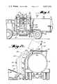
- FIG. 1is a fragmentary schematic elevational view of a vehicle to the side of which the loading assembly of the present invention has been attached;
- FIG. 2is a schematic rear view of the vehicle of FIG. 1;
- FIG. 3is a fragmentary perspective view of the lower end portion of the raising and lowering mechanism for the container
- FIG. 4is a fragmentary view of the raising and lowering mechanism taken generally on the line 4--4 of FIG. 1;
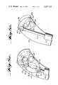
- FIG. 5ais a fragmentary view illustrating the linkage between the power source and the raising and lowering mechanism when in the lowered position
- FIG. 5bis a view corresponding to FIG. 5a with the linkage in the raised position
- FIG. 6is a fragmentary view illustrating the upper end portion of the raising and lowering mechanism at the beginning of a container-tipping operation.
- FIGS. 1 and 2illustrate a vehicle 10 having a frame 12 on which a body 14 is mounted.
- the body 14has a top opening 15 near the front end thereof for receiving trash, garbage or the like and an end gate 16 for removal of the body contents.
- the containerincludes a lid 18' hinged for swinging movement about an axis 19.
- the loaderincludes an upright mast assembly which includes two spaced-apart channel members 20 each rigidly connected at its lower end to a horizontal frame member 22 which extends transversely of the vehicle 10.
- the frame members 22are telescopically received into fixed tubular support members 24 (see FIG. 4) which are carried by the vehicle frame 12, as by means of mounting plates or the like (not shown) welded to both the support members 24 and to the frame 12.
- the frame members 22are longitudinally movable in the tubular support members 24 by means of a drive mechanism illustrated schematically at 26 (FIG. 4).
- the two upright channel members 20, which are rigidly interconnected by horizontal members 28,can therefore be moved transversely of the vehicle 10 during a container-handling operation.
- the limit positions of the channel members 20are shown in FIG. 2.
- the mast assemblyi.e.
- the two interconnected channel members 20can be mounted at or near its upper end for limited swinging movement in a vertical plane which is transverse to the axis of the vehicle 10; the important function to be attained is that of bringing the lower end of the mast assembly into engagement with the stationary container 18, as illustrated in FIG. 2.
- a container engaging or pick-up device 30is located between the two channel members 20 of the mast assembly and is arranged for guided vertical movement relative to the channel members 20.
- the engaging device 30is adapted to engage and interlock with complementary fittings on the container 18 in any convenient way. The details of the engaging device 30 therefore are not critical.
- the device 30includes a rigid horizontal support member 32 which carries two spaced-apart engaging fittings 34.
- Each fitting 34includes two vertically spaced-apart horizontal rollers 36 disposed parallel to the vehicle axis.
- the rollers 36are adapted to engage in downwardly-open, hook-shaped slots 38 formed in brackets 40 (FIGS. 2 and 6) which are rigidly secured to the ends of the container 18.
- a lock assemblyfor example as described in the aforesaid U.S. Pat. No. 3,910,434, is provided for locking the rollers 36 in the slots 38 during a container-handling operation.
- the container engaging device 30is mounted for movement along the length of the mast assembly by means of a roller connection to each of the channel members 20.
- the channel member 20(which is the right-hand channel member seen in FIG. 1) provides a slot or runway 42 which receives a pair of rollers 44 carried by a bracket 46 welded to the member 32 of the engaging device 30.
- the other channel member 20is a mirror image of the illustrated channel member and similarly cooperates with another set of rollers carried by the member 32.
- FIG. 2illustrates the container 18 in its initial position on the ground and in phantom line in its final tipped position.
- the new drive arrangementincludes a pair of identical articulated arm assemblies 50 connected between the container engaging device 30 and a rotatable horizontal shaft 52 located between and journalled near each end in the two channel members 20.
- Each assembly 50includes an upper arm 54 rigidly secured at its upper end to the rotatable shaft 52.
- the lower end of each arm 54is pivotally attached at 56 to the upper end of a lower arm 58 for rotation about a horizontal axis which is parallel to the axis of the shaft 52.
- the lower end of each lower arm 58is pivotally attached at 60 to one end of the container engaging device 30 for rotation about an axis parallel to the axis of the shaft 52.
- FIG. 4shows the sequential positions A, B, C and D of the arms 54 and 58 during the raising operation
- FIG. 2shows the position of the container on the ground and when the arm assemblies 50 have reached their limit positions.
- a preferred drive device for rotating the shaft 52includes a generally upright hydraulic piston and cylinder unit inclined slightly toward the vehicle body 10 and connected between the mast assembly and the shaft 52.
- the cylinder 62 of the unitis connected at its lower end at 64 to one of the reinforcing members 28 for pivotal movement about an axis parallel to the axis of the shaft 52.
- the piston rod 66 of the unitis connected to the shaft 52 by means of a linkage 68 which is shown schematically in FIG. 1 and in detail in FIGS. 5a and 5b. It will be seen that the path of travel of the piston rod 66 is offset from the axis of the shaft 52.
- the linkage 68includes two parts.
- the first partcomprises two parallel identical arcuate links 70 each pivotally connected at 72 at one end to the piston rod 66 and at its other end to a fixed shaft 74 which is rigidly connected at its ends to the channel members 20.
- the second part of the linkage 68includes a pair of identical two-link assemblies each having an arcuate link 76 and a shorter straight link 78.
- Each of the arcuate links 76is pivotally connected at one end at 80 to the piston rod 66 and pivotally connected at its other end at 82 to one end of the straight link 78.
- the remaining end of the straight link 78is rigidly secured to the shaft 52.
- the axis of all of the pivotal connections 72, 74, 80 and 82are parallel to the shaft 52.
- the piston and cylinder unitis operated by hydraulic circuitry which may be conventional and which is therefore not described here. Conveniently the control portion of the circuitry is located in the cab of the vehicle 10.
- the maast assemblyi.e. the two upright channel members 20 and their associated parts, is extended laterally so as to engage the container engaging assembly 30 with the container 18.
- the engaging operationmay be effected with any suitable mechanism, and in addition the actual lateral movement of the engaging device can be effected by pivotal movement of the lower end of the mast assembly rather than linear movement.
- the mast assemblyis extended by the drive device 26, and engagement with the container is accomplished by insertion of the rollers 36 into the slots 38. Subsequent retraction of the mast assembly toward the vehicle is effected in order to bring the container 18 into a correct final dumping position. If the mast assembly is pivotally attached at its upper end to the vehicle, rather than being slidably attached at its lower end, then retracting movement is not necessary.
- Elevation of the container gripping device 30is initiated by pressurizing the piston and cylinder unit so as to extend the piston rod 66 from the cylinder 62.
- This upward movement of the piston rod 66is transmitted by the linkage 68 as torque to the shaft 52 which starts to rotate clockwise as viewed in FIG. 4.
- the clockwise rotation of the lattercauses the arm 54 to begin to swing upwardly in a plane transverse to the vehicle axis.
- the lower arm 58is thereby pulled upwardly, and begins to fold toward the upper arm 54, causing the container engaging device 30 and the attached container 18 to begin moving upwardly along the channel members 20.
- Positions A and Dare the limit positions.
- the engaging device 30moves along the channel members 20, guided by the rollers 44 in the runways 42, its speed gradually increases until it reaches the curved portions of the channel members 20.
- the speed of the engaging device 30then gradually reduces until it begins to move past the axis of the shaft 52.
- a substantially constant speedis then attained and maintained until the drive system approaches maximum travel, at which time the engaging device 30 tips to effect dumping of the contents of the container 18 into the vehicle body 14.
- the dumping operationis completed when the drive system comes to a stop.
- FIGS. 5a and 5billustrate in detail the operation of the linkage 68 between the piston rod 66 and the shaft 52 during movement of the piston rod 66.
- the solid line position in FIG. 5ais the position when the piston rod 66 is fully retracted.
- the phantom line position in FIG. 5a and the solid line position in FIG. 5brepresent the position of the linkage 68 when the piston rod 66 is fully extended.
- the link 70rotates clockwise about the fixed shaft 74 through an arc.
- the articulated linkage 76, 78acts generally as a simple crank during the first portion of movement of the piston rod 66, thereby causing the shaft 52 (which is rigidly connected to the link 78) to rotate clockwise and causes the arms 54 and 58 to begin moving from position A toward positions B and C (FIG. 4), thereby moving the engaging device 30 upwardly along the straight portions of the channel members 20 at an increasing speed. That is, as the arms 54 swing upwardly, movement of the engaging device accelerates because the arms 54 are swinging with a maximum arc or radius. When the engaging device 30 begins to enter its more pronounced curved path near and at the upper ends of the channel members 20, the articulated linkage 76, 78 begins to fold about the pivot axis 82.
- the length of the radius armshortens. This in turn decelerates the engaging device 30 to a substantially constant lower speed, following which the engaging device 30 causes the container to tip toward the vehicle in a dumping operation.
- the piston rod 66is then at its fully extended position.
Landscapes
- Engineering & Computer Science (AREA)
- Mechanical Engineering (AREA)
- Forklifts And Lifting Vehicles (AREA)
Abstract
Description
Claims (7)
Priority Applications (1)
| Application Number | Priority Date | Filing Date | Title |
|---|---|---|---|
| US06/296,007US4427333A (en) | 1981-03-02 | 1981-08-25 | Loader for a vehicle body |
Applications Claiming Priority (2)
| Application Number | Priority Date | Filing Date | Title |
|---|---|---|---|
| US23958181A | 1981-03-02 | 1981-03-02 | |
| US06/296,007US4427333A (en) | 1981-03-02 | 1981-08-25 | Loader for a vehicle body |
Related Parent Applications (1)
| Application Number | Title | Priority Date | Filing Date |
|---|---|---|---|
| US23958181AContinuation-In-Part | 1981-03-02 | 1981-03-02 |
Publications (1)
| Publication Number | Publication Date |
|---|---|
| US4427333Atrue US4427333A (en) | 1984-01-24 |
Family
ID=26932687
Family Applications (1)
| Application Number | Title | Priority Date | Filing Date |
|---|---|---|---|
| US06/296,007Expired - LifetimeUS4427333A (en) | 1981-03-02 | 1981-08-25 | Loader for a vehicle body |
Country Status (1)
| Country | Link |
|---|---|
| US (1) | US4427333A (en) |
Cited By (35)
| Publication number | Priority date | Publication date | Assignee | Title |
|---|---|---|---|---|
| US4538951A (en)* | 1983-09-06 | 1985-09-03 | Crane Carrier Company | Chassiless vehicle and front refuse loader |
| GB2168316A (en)* | 1984-12-18 | 1986-06-18 | Cristina Longaretti | Device for overturning refuse bins into the body of a collection vehicle |
| US4597710A (en)* | 1984-11-28 | 1986-07-01 | Athey Products Corporation | Trash collection vehicle side-loading apparatus |
| US4669940A (en)* | 1984-05-22 | 1987-06-02 | Emco Industries, Inc. | Apparatus for handling refuse containers and the like |
| GB2191461A (en)* | 1986-06-05 | 1987-12-16 | Mackrill David Eng Ltd | Container lifting/tipping mechanism |
| GB2211166A (en)* | 1987-10-17 | 1989-06-28 | Allen Jack | Tipping bins into a refuse collection vehicle |
| US4844282A (en)* | 1987-01-13 | 1989-07-04 | Soba (Uk) Limited | Container for compacted material |
| GB2222813A (en)* | 1988-07-29 | 1990-03-21 | * Jack Allen | Refuse collection vehicle |
| US4981411A (en)* | 1989-03-06 | 1991-01-01 | Rogers Manufacturing Co., Inc. | Self-loading transport body for recyclable waste |
| US5044863A (en)* | 1990-06-06 | 1991-09-03 | Crane Carrier Company | Side refuse loader for vehicles |
| US5092731A (en)* | 1989-10-30 | 1992-03-03 | Rand Automated Compaction System, Inc. | Container handling apparatus for a refuse collection vehicle |
| US5505576A (en)* | 1995-03-09 | 1996-04-09 | Crane Carrier Company | Side loader for curbside refuse container |
| US5651654A (en)* | 1995-03-28 | 1997-07-29 | Mcneilus Truck And Manufacturing, Inc. | Tilting bin handler |
| US5775867A (en)* | 1995-12-28 | 1998-07-07 | Mcneilus Truck And Manufacturing, Inc. | Clamshell basket loader |
| US5813818A (en)* | 1995-07-31 | 1998-09-29 | Mcneilus Truck And Manufacturing, Inc. | Multi-compartment side bucket refuse collection system |
| US5931628A (en)* | 1995-03-28 | 1999-08-03 | Mcneilus Truck And Manufacturing, Inc. | Manual/automated side loader |
| US6210094B1 (en) | 1995-07-31 | 2001-04-03 | Mcneilus Truck And Manufacturing, Inc. | Refuse collection system |
| US20020119034A1 (en)* | 1999-12-10 | 2002-08-29 | Ramiro Arrez | Retractable lifter for refuse container |
| US20020141855A1 (en)* | 2001-04-02 | 2002-10-03 | Ramiro Arrez | Refuse receptacle lifter |
| US20030099529A1 (en)* | 1999-12-10 | 2003-05-29 | Ramiro Arrez | Refuse container lifter |
| US20050111942A1 (en)* | 2003-11-20 | 2005-05-26 | James Rimsa | Front mounted lifter for front load vehicle and refuse collection method |
| US6921239B2 (en) | 2001-03-30 | 2005-07-26 | Perkins Manufacturing Company | Damage-resistant refuse receptacle lifter |
| US20050169734A1 (en)* | 2004-01-29 | 2005-08-04 | Ramiro Arrez | Heavy duty cart lifter |
| US20070183872A1 (en)* | 2006-02-09 | 2007-08-09 | Ramiro Arrez | Adaptable cart lifter |
| US20070243050A1 (en)* | 2006-04-17 | 2007-10-18 | Carlos Arrez | Front load container lifter |
| US20080035176A1 (en)* | 2004-08-25 | 2008-02-14 | Byers Ernest F | Automated Cart and Container Cleaning System |
| US20080105761A1 (en)* | 2004-08-25 | 2008-05-08 | Blast N Clean Llc | Interior and exterior cleaning of waste carts and containers |
| US20080105474A1 (en)* | 2004-08-25 | 2008-05-08 | Blast N Clean Llc | Cart and container cleaning system with heated fluid |
| US20080110476A1 (en)* | 2004-08-25 | 2008-05-15 | Blast N Clean Llc | Container cleaning system using nozzles |
| US20090067965A1 (en)* | 2003-08-11 | 2009-03-12 | Collectech Designs, L.L.C. | Side-loading refuse collection apparatus and method |
| US20110038697A1 (en)* | 2009-08-17 | 2011-02-17 | Carlos Arrez | Side loading refuse collection system |
| US20110188978A1 (en)* | 2010-02-02 | 2011-08-04 | Romacly Glenn A | Articulated lift arm |
| US8827559B2 (en) | 2012-08-23 | 2014-09-09 | The Heil Co. | Telescopic arm for a refuse vehicle |
| US10144584B2 (en) | 2013-10-01 | 2018-12-04 | The Curotto-Can, Llc | Intermediate container for a front loading refuse container |
| US10661986B2 (en) | 2011-08-11 | 2020-05-26 | The Heil Co. | Refuse collection vehicle with telescoping arm |
Citations (2)
| Publication number | Priority date | Publication date | Assignee | Title |
|---|---|---|---|---|
| US3844434A (en) | 1972-11-20 | 1974-10-29 | Fabit Corp | Refuse container loading and transport assembly |
| US3910434A (en) | 1973-10-29 | 1975-10-07 | Franklin D Ebeling | Mechanically actuated side loading arrangement for a vehicle body |
- 1981
- 1981-08-25USUS06/296,007patent/US4427333A/ennot_activeExpired - Lifetime
Patent Citations (2)
| Publication number | Priority date | Publication date | Assignee | Title |
|---|---|---|---|---|
| US3844434A (en) | 1972-11-20 | 1974-10-29 | Fabit Corp | Refuse container loading and transport assembly |
| US3910434A (en) | 1973-10-29 | 1975-10-07 | Franklin D Ebeling | Mechanically actuated side loading arrangement for a vehicle body |
Cited By (57)
| Publication number | Priority date | Publication date | Assignee | Title |
|---|---|---|---|---|
| US4538951A (en)* | 1983-09-06 | 1985-09-03 | Crane Carrier Company | Chassiless vehicle and front refuse loader |
| US4669940A (en)* | 1984-05-22 | 1987-06-02 | Emco Industries, Inc. | Apparatus for handling refuse containers and the like |
| US4597710A (en)* | 1984-11-28 | 1986-07-01 | Athey Products Corporation | Trash collection vehicle side-loading apparatus |
| GB2168316A (en)* | 1984-12-18 | 1986-06-18 | Cristina Longaretti | Device for overturning refuse bins into the body of a collection vehicle |
| FR2574765A1 (en)* | 1984-12-18 | 1986-06-20 | Longaretti Cristina | DEVICE FOR TILTING A GARBAGE CONTAINER INTO THE INTERIOR OF A GARBAGE COLLECTOR |
| GB2191461B (en)* | 1986-06-05 | 1990-07-11 | Mackrill David Eng Ltd | Container lifting/tipping mechanism |
| GB2191461A (en)* | 1986-06-05 | 1987-12-16 | Mackrill David Eng Ltd | Container lifting/tipping mechanism |
| US4844282A (en)* | 1987-01-13 | 1989-07-04 | Soba (Uk) Limited | Container for compacted material |
| GB2211166A (en)* | 1987-10-17 | 1989-06-28 | Allen Jack | Tipping bins into a refuse collection vehicle |
| GB2222813A (en)* | 1988-07-29 | 1990-03-21 | * Jack Allen | Refuse collection vehicle |
| US4981411A (en)* | 1989-03-06 | 1991-01-01 | Rogers Manufacturing Co., Inc. | Self-loading transport body for recyclable waste |
| US5092731A (en)* | 1989-10-30 | 1992-03-03 | Rand Automated Compaction System, Inc. | Container handling apparatus for a refuse collection vehicle |
| US5360310A (en)* | 1989-10-30 | 1994-11-01 | Rand Automated Compaction System, Inc. | Container handling apparatus for a refuse collection vehicle |
| US5044863A (en)* | 1990-06-06 | 1991-09-03 | Crane Carrier Company | Side refuse loader for vehicles |
| US5505576A (en)* | 1995-03-09 | 1996-04-09 | Crane Carrier Company | Side loader for curbside refuse container |
| US5651654A (en)* | 1995-03-28 | 1997-07-29 | Mcneilus Truck And Manufacturing, Inc. | Tilting bin handler |
| US5931628A (en)* | 1995-03-28 | 1999-08-03 | Mcneilus Truck And Manufacturing, Inc. | Manual/automated side loader |
| US6210094B1 (en) | 1995-07-31 | 2001-04-03 | Mcneilus Truck And Manufacturing, Inc. | Refuse collection system |
| US6390758B1 (en) | 1995-07-31 | 2002-05-21 | Mcneilus Truck And Manufacturing, Inc. | Refuse collection system |
| US5813818A (en)* | 1995-07-31 | 1998-09-29 | Mcneilus Truck And Manufacturing, Inc. | Multi-compartment side bucket refuse collection system |
| US5919027A (en)* | 1995-12-28 | 1999-07-06 | Mcneilus Truck And Manufacturing, Inc. | Clamshell basket loader |
| US5934858A (en)* | 1995-12-28 | 1999-08-10 | Mcneilus Truck And Manufacturing, Inc. | Clamshell basket loader |
| US6213706B1 (en) | 1995-12-28 | 2001-04-10 | Mcneilus Truck And Manufacturing, Inc. | Clamshell basket loader |
| US5775867A (en)* | 1995-12-28 | 1998-07-07 | Mcneilus Truck And Manufacturing, Inc. | Clamshell basket loader |
| US20020119034A1 (en)* | 1999-12-10 | 2002-08-29 | Ramiro Arrez | Retractable lifter for refuse container |
| US6929441B2 (en) | 1999-12-10 | 2005-08-16 | Perkins Manufacturing Company | Refuse container lifter |
| US20030099529A1 (en)* | 1999-12-10 | 2003-05-29 | Ramiro Arrez | Refuse container lifter |
| US6884017B2 (en) | 1999-12-10 | 2005-04-26 | Perkins Manufacturing Company | Retractable lifter for refuse container |
| US6921239B2 (en) | 2001-03-30 | 2005-07-26 | Perkins Manufacturing Company | Damage-resistant refuse receptacle lifter |
| US20020141855A1 (en)* | 2001-04-02 | 2002-10-03 | Ramiro Arrez | Refuse receptacle lifter |
| US20060072991A1 (en)* | 2001-04-02 | 2006-04-06 | Ramiro Arrez | Refuse receptacle lifter |
| US7128515B2 (en) | 2001-04-02 | 2006-10-31 | Perkins Manufacturing Company | Refuse receptacle lifter |
| US20090067965A1 (en)* | 2003-08-11 | 2009-03-12 | Collectech Designs, L.L.C. | Side-loading refuse collection apparatus and method |
| US20050111942A1 (en)* | 2003-11-20 | 2005-05-26 | James Rimsa | Front mounted lifter for front load vehicle and refuse collection method |
| US7390159B2 (en) | 2003-11-20 | 2008-06-24 | Perkins Manufacturing Company | Front mounted lifter for front load vehicle |
| US7273340B2 (en) | 2004-01-29 | 2007-09-25 | Perkins Manufacturing Company | Heavy duty cart lifter |
| US20050169734A1 (en)* | 2004-01-29 | 2005-08-04 | Ramiro Arrez | Heavy duty cart lifter |
| US20080035176A1 (en)* | 2004-08-25 | 2008-02-14 | Byers Ernest F | Automated Cart and Container Cleaning System |
| US20080105761A1 (en)* | 2004-08-25 | 2008-05-08 | Blast N Clean Llc | Interior and exterior cleaning of waste carts and containers |
| US20080105474A1 (en)* | 2004-08-25 | 2008-05-08 | Blast N Clean Llc | Cart and container cleaning system with heated fluid |
| US20080110476A1 (en)* | 2004-08-25 | 2008-05-15 | Blast N Clean Llc | Container cleaning system using nozzles |
| US7806645B2 (en) | 2006-02-09 | 2010-10-05 | Perkins Manufacturing Company | Adaptable cart lifter |
| US20070183872A1 (en)* | 2006-02-09 | 2007-08-09 | Ramiro Arrez | Adaptable cart lifter |
| US20070243050A1 (en)* | 2006-04-17 | 2007-10-18 | Carlos Arrez | Front load container lifter |
| US7871233B2 (en) | 2006-04-17 | 2011-01-18 | Perkins Manufacturing Company | Front load container lifter |
| US20110038697A1 (en)* | 2009-08-17 | 2011-02-17 | Carlos Arrez | Side loading refuse collection system |
| US20110188978A1 (en)* | 2010-02-02 | 2011-08-04 | Romacly Glenn A | Articulated lift arm |
| US8100622B2 (en) | 2010-02-02 | 2012-01-24 | Rainbow Conversion Technologies, Llc | Articulated lift arm |
| US10661986B2 (en) | 2011-08-11 | 2020-05-26 | The Heil Co. | Refuse collection vehicle with telescoping arm |
| US11319148B2 (en) | 2011-08-11 | 2022-05-03 | The Heil Co. | Refuse collection vehicle with telescoping arm |
| US10865827B2 (en) | 2012-08-23 | 2020-12-15 | The Heil Co. | Telescopic arm for a refuse vehicle |
| US10274006B2 (en) | 2012-08-23 | 2019-04-30 | The Heil Company | Telescopic arm for a refuse vehicle |
| US9556898B2 (en) | 2012-08-23 | 2017-01-31 | The Heil Co. | Telescopic arm for a refuse vehicle |
| US11280368B2 (en) | 2012-08-23 | 2022-03-22 | The Heil Company | Telescopic arm for a refuse vehicle |
| US8827559B2 (en) | 2012-08-23 | 2014-09-09 | The Heil Co. | Telescopic arm for a refuse vehicle |
| US11933352B2 (en) | 2012-08-23 | 2024-03-19 | The Heil Company | Telescopic arm for a refuse vehicle |
| US10144584B2 (en) | 2013-10-01 | 2018-12-04 | The Curotto-Can, Llc | Intermediate container for a front loading refuse container |
Similar Documents
| Publication | Publication Date | Title |
|---|---|---|
| US4427333A (en) | Loader for a vehicle body | |
| US4872801A (en) | Side refuse loader for vehicles | |
| US4313707A (en) | Side loading apparatus for trash collection system | |
| US4219298A (en) | Rapid rail | |
| US5702225A (en) | Boomless automated side loader for refuse collection vehicle having lift arm with non-extendable upper end | |
| US4382591A (en) | Clamping means for trough of pipe handling apparatus | |
| US7559735B2 (en) | Automated loader | |
| US3910434A (en) | Mechanically actuated side loading arrangement for a vehicle body | |
| US20220315329A1 (en) | Mechanical arm system for collecting garbage from a garbage container | |
| US3499558A (en) | Loading device | |
| US3143230A (en) | Refuse vehicle | |
| US2988832A (en) | Positive ejection mechanism for earth moving apparatus | |
| US4245732A (en) | Compactly foldable radial luffing stacker | |
| US5474413A (en) | Vehicle for collecting and transporting waste materials | |
| US3773197A (en) | Refuse container loading and transport system and apparatuses therefor | |
| US5044863A (en) | Side refuse loader for vehicles | |
| US3837512A (en) | Refuse truck container handling mechanism | |
| US2538505A (en) | Power-operated shovel | |
| GB2191461A (en) | Container lifting/tipping mechanism | |
| US4373856A (en) | Tie butt handler | |
| US3174636A (en) | Container handling equipment | |
| US5059081A (en) | Refuse truck container handling apparatus | |
| US3115736A (en) | Bag closing apparatus | |
| US2652163A (en) | Garbage disposal unit | |
| US3130846A (en) | Front end loader equipment |
Legal Events
| Date | Code | Title | Description |
|---|---|---|---|
| STCF | Information on status: patent grant | Free format text:PATENTED CASE | |
| AS | Assignment | Owner name:EBELING MANUFACTURING CORPORATION, PLAINVIEW, TEXA Free format text:ASSIGNMENT OF ASSIGNORS INTEREST.;ASSIGNOR:EBELING, FRANKLIN D.;REEL/FRAME:004497/0036 Effective date:19820606 Owner name:EMCO MANUFACTURING CORPORATION, A CORP. OF TEXAS Free format text:ASSIGNMENT OF ASSIGNORS INTEREST.;ASSIGNOR:EBELING MANUFACTURING CORPORATION, A CORP. OF TX;REEL/FRAME:004497/0038 Effective date:19820727 | |
| AS | Assignment | Owner name:EMCO INDUSTRIES, INC., PLAINVIEW, TEXAS, A CORP OF Free format text:ASSIGNMENT OF ASSIGNORS INTEREST.;ASSIGNOR:EMCO MANUFACTURING CORPORATION, A CORP OF TX.;REEL/FRAME:004548/0844 Effective date:19860418 Owner name:EMCO INDUSTRIES, INC., TEXAS Free format text:ASSIGNMENT OF ASSIGNORS INTEREST;ASSIGNOR:EMCO MANUFACTURING CORPORATION, A CORP OF TX.;REEL/FRAME:004548/0844 Effective date:19860418 | |
| MAFP | Maintenance fee payment | Free format text:PAYMENT OF MAINTENANCE FEE, 4TH YEAR, PL 96-517 (ORIGINAL EVENT CODE: M170); ENTITY STATUS OF PATENT OWNER: LARGE ENTITY Year of fee payment:4 | |
| FEPP | Fee payment procedure | Free format text:PAYOR NUMBER ASSIGNED (ORIGINAL EVENT CODE: ASPN); ENTITY STATUS OF PATENT OWNER: LARGE ENTITY | |
| MAFP | Maintenance fee payment | Free format text:PAYMENT OF MAINTENANCE FEE, 8TH YEAR, PL 96-517 (ORIGINAL EVENT CODE: M171); ENTITY STATUS OF PATENT OWNER: LARGE ENTITY Year of fee payment:8 | |
| MAFP | Maintenance fee payment | Free format text:PAYMENT OF MAINTENANCE FEE, 12TH YEAR, LARGE ENTITY (ORIGINAL EVENT CODE: M185); ENTITY STATUS OF PATENT OWNER: LARGE ENTITY Year of fee payment:12 | |
| FEPP | Fee payment procedure | Free format text:PAYOR NUMBER ASSIGNED (ORIGINAL EVENT CODE: ASPN); ENTITY STATUS OF PATENT OWNER: LARGE ENTITY Free format text:PAYER NUMBER DE-ASSIGNED (ORIGINAL EVENT CODE: RMPN); ENTITY STATUS OF PATENT OWNER: LARGE ENTITY | |
| AS | Assignment | Owner name:CENTRAL TANK OF OKLAHOMA, INC., OKLAHOMA Free format text:ASSIGNMENT OF ASSIGNORS INTEREST;ASSIGNOR:EMCO INDUSTRIES, INC.;REEL/FRAME:008153/0098 Effective date:19940520 |