US4426741A - Intraocular lens with rotatable appendage - Google Patents
Intraocular lens with rotatable appendageDownload PDFInfo
- Publication number
- US4426741A US4426741AUS06/366,583US36658382AUS4426741AUS 4426741 AUS4426741 AUS 4426741AUS 36658382 AUS36658382 AUS 36658382AUS 4426741 AUS4426741 AUS 4426741A
- Authority
- US
- United States
- Prior art keywords
- appendage
- intraocular lens
- optical
- enclosure
- appendages
- Prior art date
- Legal status (The legal status is an assumption and is not a legal conclusion. Google has not performed a legal analysis and makes no representation as to the accuracy of the status listed.)
- Expired - Fee Related
Links
- 230000003287optical effectEffects0.000claimsabstractdescription74
- 238000000034methodMethods0.000claimsdescription5
- 210000002159anterior chamberAnatomy0.000description8
- 230000007246mechanismEffects0.000description5
- 238000010276constructionMethods0.000description3
- 230000008602contractionEffects0.000description3
- 239000000463materialSubstances0.000description3
- 229920003229poly(methyl methacrylate)Polymers0.000description3
- 239000004926polymethyl methacrylateSubstances0.000description3
- 238000001356surgical procedureMethods0.000description3
- 230000001886ciliary effectEffects0.000description2
- 210000004087corneaAnatomy0.000description2
- 230000006378damageEffects0.000description2
- 210000003038endotheliumAnatomy0.000description2
- 238000003780insertionMethods0.000description2
- 230000037431insertionEffects0.000description2
- 210000001747pupilAnatomy0.000description2
- 210000001519tissueAnatomy0.000description2
- 206010007772Cataract conditionsDiseases0.000description1
- 239000004743PolypropyleneSubstances0.000description1
- 206010036346Posterior capsule opacificationDiseases0.000description1
- 238000010521absorption reactionMethods0.000description1
- 230000007423decreaseEffects0.000description1
- 230000003247decreasing effectEffects0.000description1
- 210000002889endothelial cellAnatomy0.000description1
- 208000030533eye diseaseDiseases0.000description1
- 230000001771impaired effectEffects0.000description1
- 238000004519manufacturing processMethods0.000description1
- 239000005304optical glassSubstances0.000description1
- 230000002085persistent effectEffects0.000description1
- -1polypropylenePolymers0.000description1
- 229920001155polypropylenePolymers0.000description1
- 238000010008shearingMethods0.000description1
- 210000004127vitreous bodyAnatomy0.000description1
Images

Classifications
- A—HUMAN NECESSITIES
- A61—MEDICAL OR VETERINARY SCIENCE; HYGIENE
- A61F—FILTERS IMPLANTABLE INTO BLOOD VESSELS; PROSTHESES; DEVICES PROVIDING PATENCY TO, OR PREVENTING COLLAPSING OF, TUBULAR STRUCTURES OF THE BODY, e.g. STENTS; ORTHOPAEDIC, NURSING OR CONTRACEPTIVE DEVICES; FOMENTATION; TREATMENT OR PROTECTION OF EYES OR EARS; BANDAGES, DRESSINGS OR ABSORBENT PADS; FIRST-AID KITS
- A61F2/00—Filters implantable into blood vessels; Prostheses, i.e. artificial substitutes or replacements for parts of the body; Appliances for connecting them with the body; Devices providing patency to, or preventing collapsing of, tubular structures of the body, e.g. stents
- A61F2/02—Prostheses implantable into the body
- A61F2/14—Eye parts, e.g. lenses or corneal implants; Artificial eyes
- A61F2/16—Intraocular lenses
- A61F2002/1681—Intraocular lenses having supporting structure for lens, e.g. haptics
- A61F2002/1683—Intraocular lenses having supporting structure for lens, e.g. haptics having filiform haptics
- A61F2002/1686—Securing a filiform haptic to a lens body
Definitions
- the present inventionrelates to an intraocular lens which may be implanted in the anterior or posterior chamber of the eye after removal of the natural lens of an eye as a result of a cataract condition.
- Intraocular lenseshave been successfully used to correct impaired vision after cataract surgery.
- a persistent problemhas been the proper fitting of intraocular lenses, thus obviating the necessity of reentry into the eye and replacement of the lens.
- dislocation of the intraocular lens after placementhas caused problems in destruction of endothelial cells, infliction of pain, resulting in reentry into the eye to relocate the errant lens.
- anterior chamber lensis a fairly common procedure. It is believed that placement of an intraocular lens in the anterior chamber of the eye may be accomplished by a less demanding surgical effort. Also, the optical results from an intraocular lens placed in the anterior chamber has been found to be satisfactory. However, there is a distinct danger of destruction of the endothelium layer of the cornea as a result of touching of the same. This touching may occur during the surgical insertion of the intraocular lens or if the intraocular lens in the anterior chamber dislocates or moves forward with changes in the shape of the eye. It has recently been found that it is best for an intraocular lens to not touch the iris portion of the eye in the vicinity of the pupil.
- U.S. Pat. No. 3,994,027 to Jensen, et aldescribed a vaulted intraocular lens. Vaulting and adjustability of the fixation mechanism of an intraocular lens has also been found to be useful in the posterior chamber of the eye to avoid touching the iris and to insure that dislocation of the intraocular lens does not occur when the lens is being supported by the ciliary sulcus.
- An intraocular lenswhich may be placed either in the anterior or posterior chamber of the eye that is adjustable in its overall dimension without thrusting generally at right angles to the deformation force applied would be a very useful advance in the art of manufacture of intraocular lenses and treatment of eye diseases.
- the intraocular lens of the present inventionutilizes an optical portion with or without a haptic with the proper optical correction determined by prior art methods.
- At least one appendageis associated with the optical portion by a rotatable connection.
- the appendageincludes at least a first portion and a connected second portion.
- Meansis also provided for permitting rotation in one direction of the first portion of the appendage in relation to the optical portion upon the application of an actuating force on the second portion of the appendage. Rotation in the opposite direction of the first portion of the appendage occurs upon removal of the actuating force.
- the appendagemay be constructed of flexible material which is nonreactive to biological tissue.
- the intraocular lens of the present inventionmay also embrace the addition of a third portion of the appendage which is connected to the second portion and means for permitting rotation of the third portion in relation to the optical portion of the lens. Rotation of the third portion would occur again with application of an actuating force upon the second portion of the appendage which extends away from the optical portion to a distance further than the first or third portions of the appendage.
- a closed loopwould be formed in this aspect of the invention such that the second portion of the appendage includes a proximal part connected to the first and third portions of the appendage, and a distal part extending from the optical portion to receive the actuating force.
- the actuating forcemay be applied by the periphery of the eye during initial placement or upon contraction postoperatively.
- the distal part of the second portionmay be offset from the connection of the first and third portions to the optical portion of the lens to cause rotation of the first and third portions in the same direction relative to the optical portion upon the application of the actuating force.
- the distal part of the second portionmay be placed such that the actuating force causes rotation of the first and third portions in the opposite direction relative to the optical portion when the actuating force is applied. It should be noted that the relative rotation may actually cause rotation of the optical portion about its axis without a thrust along the optical axis.
- the means for permitting rotation of the first or third portions of the appendagemay include an enclosure connected to the optical portion or a hole or opening in the optical portion.
- the first portion of the appendagemay freely rotate within the enclosure or opening.
- a confining meansmay include an enlarged portion of the opening as well as an enlargement on the first portion of the appendage.
- the second portion of the appendagemay be angularly disposed in relation to the first appendage immediately adjacent the lens portion. Such angular connection may include a vaulting configuration described in the prior art.
- the intraocular lens herein describedmay also be constructed with a plurality of appendages to provide multiple point fixation within the chosen chamber of the eye.
- the invention provided hereinmay also be considered to include a method of fixing an appendage to an intraocular lens using the steps of creating an opening in the optical portion with enlargement.
- the first portion of an appendageis placed in the opening such that the second portion of the appendage remains outside the same.
- An enlargementis made in the first portion of the appendage within the enlargement portion of the opening such that the enlarged part of the first portion of the appendage cannot pass to the unenlarged portion of the opening.
- the second portionis angularly disposed in relation to the first portion immediately adjacent the lens portion. Of course, this angular disposition may provide a vaulting of the lens.
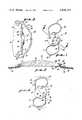
- FIG. 1is a top plan view of an embodiment of the present invention.
- FIG. 2is a slightly broken sectional view taken along line 2--2 of FIG. 1.
- FIG. 3is a sectional view showing the lens of FIG. 1 within the anterior chamber of an eye.
- FIG. 4is a top plan view of the lens of the FIG. 1 showing the exertion of forces thereupon schematically.
- FIG. 5is a top plan view of another embodiment of the present invention.
- FIG. 6is a broken sectional view of another embodiment of the appendage fixation mechanism of the present invention.
- FIG. 7is a top plan view of another embodiment of the present invention.
- FIG. 8is a side elevational view of the embodiment of the present invention depicted in FIG. 7.
- optical portion 12may be constructed of any known materials which provides the optical correction desired. Optical portion 12 must be nonreactive with human tissue, such as polymethylmethacrylate (PMMA), optical glass, and the like. Although not depicted in the drawings, optical portion 12 may include a haptic to aid in the handling of lens 10.
- PMMApolymethylmethacrylate
- optical portion 12may include a haptic to aid in the handling of lens 10.
- an appendage 14Connected to optical portion 12 is an appendage 14 which may be constructed of flexible material, such as PMMA, polypropylene, and the like.
- Appendage 14includes a first portion 16 angularly connected to second portion 18.
- a second appendage 20is depicted which is constructed similarly to first appendage 14.
- means 22is also included for permitting rotation of first portion 16 in relation to optical portion 12 upon the application of an actuating force, arrow 24, on second portion 18, FIG. 1.
- a comparable force, arrow 26may be placed on second appendage 20 and will be hereinafter described with reference to FIG. 4. As shown in FIG.
- means 22rotates first portion 16 in a clockwise direction upon the application of force 24 and in the opposite counterclockwise direction upon the removal of force 24.
- Second portion 18may gain purchase from a portion of the eye or optical portion 12 at a place beyond the point of the application of force 24. As depicted in FIG. 1, it may be seen that second portion 18 connects to a third portion 28 which also includes means for permitting rotation similar to means 22.
- Means 22includes a cavity or enclosure 30 having an enlarged portion 32.
- Enclosure 30is formed by creating an opening through optical portion 12, but may be formed in other ways such as attaching a bushing or the like to optical portion 12.
- the first portion 16also possesses an enlargement 34 which fits within an enlarged opening 32 of cavity 30.
- Second portion 18is angularly connected to first portion 16 immediately adjacent the under surface 36 of optical portion 12.
- means 38is provided for confining enlargement 34 to enlarged portion 32 of cavity 30.
- a second enclosure 40, FIG. 1,is similarly constructed to cavity or enclosure 30.
- enclosures 42 and 44provide means for rotation of appendage 20 relative to optical portion 12.
- lens 10is placed in the anterior chamber 46 of eye 48. Lens 10 may also be placed in posterior chamber 50.
- First appendage 14 and second appendage 20extend to and contact angle 54 formed by the meeting of cornea 56 and iris 58. It should be noted that appendages 14 and 20 are vaulted or angled away from the portion of the iris adjacent pupil 60 forming gaps 62 and 64 thereby.
- optical axis 66is illustrated.
- Second portion 18 of first appendage 14may be deemed to include a proximal part 68 and a distal part 70 extending from the optical portion 12.
- Proximal part 68connects to first portion 16 and third portion 28 of first appendage 14. It may be apparent that the proximal part 68 of second portion 14 angularly connects to the first and third portions 16 and 28 of first appendage 14.
- Distal part 70is also angularly disposed in relation to proximal part 68 of second portion of first appendage 14. This provision decreases the vaulting angle and the span of gaps 62 and 64 between iris 58 and optical portion 12.
- distal part 70 of second portion 18 of first appendage 14contacts the periphery of eye 48, namely angle 54.
- the comparable part of second appendage 20also initally contacts angle 54.
- the position of appendages 14 and 20 in relation to angle 54are shown in phantom on FIG. 4.
- lens 10takes the configuration shown in solid line format in FIG. 4.
- arrows 72 and 74show the relative rotation of appendages 14 and 20 in relation to optical portion 12. In actuality, it has been found that optical portion 12 appears to rotate about optical axis 66.
- distal part 70 of second portion 18 of first appendage 14is offset from a line 76 between cavities 30 and 40 and cavities 42 and 78 of optical portion 12.
- third portion 28 and first portion 16 of appendage 14rotate in the same direction upon the application of an actuating force on distal part 70 of appendage 14. The complete operation of lens 10 will be described as the specification continues.
- Lens 10Aincludes appendages 80, 82, and 84 rotatably connected to optical portion 12. Again, the distal parts of appendages 80, 82, and 84 offset to produce rotation within cavities or enclosures 86, 88, 90, 92, 94, and 96. Appendages 80, 82, and 84, may be considered identical in construction to appendage 14 hereinabove described. Lens 10A obtains three point fixation in either in the anterior or posterior chamber of the eye. It should also be noted that any plurality of appendages may be affixed to optical portion 12 to obtain more than three point fixation within the limitations of size and the shape of the optical portion and/or the appendages.
- FIG. 6demonstrates a variation of appendage 14 wherein appendage 14A is shown having a first portion 98 having an enlargement 100.
- a cavity 102includes an enlarged portion 104 adjacent the under surface 106 of optical portion 12.
- Second portion 106is also depicted as being vaulted to remove optical portion 12 and the bulk of second portion 106 from contact with the pupiliary portion of iris 58.
- FIG. 7depicts another embodiment, lens 10B, of the present invention where a first appendage 108 and a second appendage 110 rotatably connect to optical portion 12.
- First portion 112 and third portion 114 of appendage 108are constructed to rotate within cavities 116 and 118.
- first portion 120 and third portion 122rotate within cavities 124 and 126.
- the means for permitting rotation of first and third portions 112 and 114 and 124 and 126 of appendages 108 and 110 respectively,would be similar to the construction of first and third portions 16 and 28 of appendage 14, hereinbefore described.
- force arrows 128 and 130show second portions 132 and 138 of appendages 108 and 110 rotate the respective first and third portions 16 and 28 in opposite directions.
- FIG. 8illustrates the vaulting construction used for the same purposes as the prior embodiments.
- lens 10, 10A, or 10Bhaving the proper optical correction in optical portion 12.
- the intraocular lenswould be sized slightly larger than the overall dimension of the anterior or posterior chambers 46 or 50 of eye 48.
- the overall dimension of the lenswould be manually compressed and then permitted to expand slightly such that the lens 10 would wedge into the angle 52, 54, or the ciliary sulcus 136 (posterior chamber).
- the compressing, manually or by contraction of the overall dimension of the eyewould cause rotation of the appendages in relation to the optical portion 12.
- lens portion 12rotates about optical axis 66 when force is applied at force arrows 24 and 26, FIG. 1.
- the flexibility of the appendages associated with lens 10, 10A, and/or 10Bwould aid in the absorption of forces exerted on the appendages. Release of the force would permit the appendages to return or spring back to their original position.
- the inventionmay also be deemed to include a method of fixing an appendage such as appendage 14 to an intraocular lens utilizing the steps of creating an opening 30 within optical portion 12.
- the opening 30would include an enlargement 32.
- a first portion 16 of appendage 14will be placed into opening 30 such that the second portion 18 remains outside of opening 30.
- Enlargement 34would then be created on the first portion 16 of appendage 14 such that the enlargement fit within the enlarged portion 32 of opening 30.
- enlargement 34would be unable to pass through the remaining unenlarged portion of opening 30.
- the second portion 18would be angularly disposed in relation to first portion 16 of appendage 14 immediately adjacent the undersurface 36 of lens portion 12.
Landscapes
- Health & Medical Sciences (AREA)
- Ophthalmology & Optometry (AREA)
- Cardiology (AREA)
- Oral & Maxillofacial Surgery (AREA)
- Transplantation (AREA)
- Engineering & Computer Science (AREA)
- Biomedical Technology (AREA)
- Heart & Thoracic Surgery (AREA)
- Vascular Medicine (AREA)
- Life Sciences & Earth Sciences (AREA)
- Animal Behavior & Ethology (AREA)
- General Health & Medical Sciences (AREA)
- Public Health (AREA)
- Veterinary Medicine (AREA)
- Prostheses (AREA)
Abstract
Description
Claims (20)
Priority Applications (1)
| Application Number | Priority Date | Filing Date | Title |
|---|---|---|---|
| US06/366,583US4426741A (en) | 1982-04-08 | 1982-04-08 | Intraocular lens with rotatable appendage |
Applications Claiming Priority (1)
| Application Number | Priority Date | Filing Date | Title |
|---|---|---|---|
| US06/366,583US4426741A (en) | 1982-04-08 | 1982-04-08 | Intraocular lens with rotatable appendage |
Publications (1)
| Publication Number | Publication Date |
|---|---|
| US4426741Atrue US4426741A (en) | 1984-01-24 |
Family
ID=23443624
Family Applications (1)
| Application Number | Title | Priority Date | Filing Date |
|---|---|---|---|
| US06/366,583Expired - Fee RelatedUS4426741A (en) | 1982-04-08 | 1982-04-08 | Intraocular lens with rotatable appendage |
Country Status (1)
| Country | Link |
|---|---|
| US (1) | US4426741A (en) |
Cited By (41)
| Publication number | Priority date | Publication date | Assignee | Title |
|---|---|---|---|---|
| WO1985002995A1 (en)* | 1984-01-05 | 1985-07-18 | V T P "Maimex" | Artificial intraocular lens |
| US4543673A (en)* | 1983-06-03 | 1985-10-01 | Surgidev Corporation | Vaulted intraocular lens |
| US4580299A (en)* | 1983-10-19 | 1986-04-08 | Surgidev Corp. | Intraocular lens |
| US4610689A (en)* | 1983-07-29 | 1986-09-09 | Graether John M | Intraocular lens |
| US4629460A (en)* | 1984-06-25 | 1986-12-16 | Dyer Robert L | Intraocular lens |
| US4655770A (en)* | 1985-06-06 | 1987-04-07 | Ioptex, Inc. | Surface passivated intraocular lens |
| US4666445A (en)* | 1985-10-01 | 1987-05-19 | Tillay Michael J | Intraocular lens with shape memory alloy haptic/optic and method of use |
| US4666444A (en)* | 1985-09-13 | 1987-05-19 | Pannu Jaswant S | Easily insertable intraocular lens |
| EP0215468A3 (en)* | 1985-09-14 | 1987-09-30 | Fromberg, Gunther, Dr. | Artificial lens for implantation in the eye |
| US5047052A (en)* | 1987-11-06 | 1991-09-10 | Seymour Dubroff | Anterior chamber intraocular lens with four point fixation |
| WO1996015734A3 (en)* | 1994-11-21 | 1996-09-12 | Acuity Israel Limited | Accommodating intraocular lens implant |
| US6013101A (en)* | 1994-11-21 | 2000-01-11 | Acuity (Israel) Limited | Accommodating intraocular lens implant |
| US6136026A (en)* | 1997-07-28 | 2000-10-24 | Israel; Henry M. | Intraocular ring |
| US6488708B2 (en) | 1999-04-09 | 2002-12-03 | Faezeh Sarfarazi | Open chamber, elliptical, accommodative intraocular lens system |
| US20040015236A1 (en)* | 1991-11-18 | 2004-01-22 | Sarfarazi Faezeh M. | Sarfarazi elliptical accommodative intraocular lens for small incision surgery |
| US20050165409A1 (en)* | 2000-12-01 | 2005-07-28 | Rolf Eckmiller | Removable implant fixing device |
| US20050267575A1 (en)* | 2001-01-25 | 2005-12-01 | Nguyen Tuan A | Accommodating intraocular lens system with aberration-enhanced performance |
| US20060100703A1 (en)* | 2004-11-10 | 2006-05-11 | Scott Evans | Method of implanting an intraocular lens |
| US20060184244A1 (en)* | 2005-02-14 | 2006-08-17 | Nguyen Tuan A | Biasing system for intraocular lens |
| US20070050025A1 (en)* | 2001-01-25 | 2007-03-01 | Nguyen Tuan A | Hydraulic configuration for intraocular lens system |
| US20070108643A1 (en)* | 2001-01-25 | 2007-05-17 | Gholam-Reza Zadno-Azizi | Single-piece accommodating intraocular lens system |
| US20070213816A1 (en)* | 1999-04-09 | 2007-09-13 | Mona Sarfarazi | Interior bag for a capsular bag and injector |
| US20070260309A1 (en)* | 2006-05-08 | 2007-11-08 | Richardson Gary A | Accommodating intraocular lens having a recessed anterior optic |
| US20070260310A1 (en)* | 2006-05-08 | 2007-11-08 | Richardson Gary A | Accommodative Intraocular Lens Having Defined Axial Compression Characteristics |
| US20080154364A1 (en)* | 2006-12-22 | 2008-06-26 | Richardson Gary A | Multi-Element Accommodative Intraocular Lens |
| US7591849B2 (en) | 2005-07-01 | 2009-09-22 | Bausch & Lomb Incorpoted | Multi-component accommodative intraocular lens with compressible haptic |
| US7662179B2 (en) | 1999-04-09 | 2010-02-16 | Sarfarazi Faezeh M | Haptics for accommodative intraocular lens system |
| US20100152846A1 (en)* | 2008-12-11 | 2010-06-17 | Yann Vaillant | Intraocular Lens and Method of Making an Intraocular Lens |
| US7780729B2 (en) | 2004-04-16 | 2010-08-24 | Visiogen, Inc. | Intraocular lens |
| US7871437B2 (en) | 2006-12-22 | 2011-01-18 | Amo Groningen B.V. | Accommodating intraocular lenses and associated systems, frames, and methods |
| US8187325B2 (en) | 2001-01-25 | 2012-05-29 | Visiogen, Inc. | Materials for use in accommodating intraocular lens system |
| US9011532B2 (en) | 2009-06-26 | 2015-04-21 | Abbott Medical Optics Inc. | Accommodating intraocular lenses |
| US9039760B2 (en) | 2006-12-29 | 2015-05-26 | Abbott Medical Optics Inc. | Pre-stressed haptic for accommodating intraocular lens |
| US9198752B2 (en) | 2003-12-15 | 2015-12-01 | Abbott Medical Optics Inc. | Intraocular lens implant having posterior bendable optic |
| US9271830B2 (en) | 2002-12-05 | 2016-03-01 | Abbott Medical Optics Inc. | Accommodating intraocular lens and method of manufacture thereof |
| US9504560B2 (en) | 2002-01-14 | 2016-11-29 | Abbott Medical Optics Inc. | Accommodating intraocular lens with outer support structure |
| US9603703B2 (en) | 2009-08-03 | 2017-03-28 | Abbott Medical Optics Inc. | Intraocular lens and methods for providing accommodative vision |
| US9814570B2 (en) | 1999-04-30 | 2017-11-14 | Abbott Medical Optics Inc. | Ophthalmic lens combinations |
| US9968441B2 (en) | 2008-03-28 | 2018-05-15 | Johnson & Johnson Surgical Vision, Inc. | Intraocular lens having a haptic that includes a cap |
| JP2019510616A (en)* | 2016-04-05 | 2019-04-18 | スリ, ガネーシュSri, Ganesh | Posterior atrium intraocular lens with swivel haptic for capsulotomy fixation |
| US11707354B2 (en) | 2017-09-11 | 2023-07-25 | Amo Groningen B.V. | Methods and apparatuses to increase intraocular lenses positional stability |
Citations (4)
| Publication number | Priority date | Publication date | Assignee | Title |
|---|---|---|---|---|
| US3913148A (en) | 1974-12-26 | 1975-10-21 | Ernst W Potthast | Intraocular lens apparatus |
| US3975779A (en) | 1975-04-09 | 1976-08-24 | American Optical Corporation | Artificial intraocular lens and supporting system therefor |
| US4257130A (en) | 1979-08-27 | 1981-03-24 | Bayers Jon Herbert | Intraocular lens mechanism |
| US4262370A (en) | 1976-08-04 | 1981-04-21 | Bausch & Lomb Incorporated | Sutureless intraocular lens |
- 1982
- 1982-04-08USUS06/366,583patent/US4426741A/ennot_activeExpired - Fee Related
Patent Citations (4)
| Publication number | Priority date | Publication date | Assignee | Title |
|---|---|---|---|---|
| US3913148A (en) | 1974-12-26 | 1975-10-21 | Ernst W Potthast | Intraocular lens apparatus |
| US3975779A (en) | 1975-04-09 | 1976-08-24 | American Optical Corporation | Artificial intraocular lens and supporting system therefor |
| US4262370A (en) | 1976-08-04 | 1981-04-21 | Bausch & Lomb Incorporated | Sutureless intraocular lens |
| US4257130A (en) | 1979-08-27 | 1981-03-24 | Bayers Jon Herbert | Intraocular lens mechanism |
Non-Patent Citations (1)
| Title |
|---|
| The Lindstrom Centrex Style 20 Posterior Chamber Lens, (Advertisement), Surgidev Corporation, Santa Barbara, Calif., 4 pp., Jan. 4, 1981. |
Cited By (59)
| Publication number | Priority date | Publication date | Assignee | Title |
|---|---|---|---|---|
| US4543673A (en)* | 1983-06-03 | 1985-10-01 | Surgidev Corporation | Vaulted intraocular lens |
| US4610689A (en)* | 1983-07-29 | 1986-09-09 | Graether John M | Intraocular lens |
| US4580299A (en)* | 1983-10-19 | 1986-04-08 | Surgidev Corp. | Intraocular lens |
| WO1985002995A1 (en)* | 1984-01-05 | 1985-07-18 | V T P "Maimex" | Artificial intraocular lens |
| GB2171910A (en)* | 1984-01-05 | 1986-09-10 | V T P Maimex | Artificial intraocular lens |
| US4629460A (en)* | 1984-06-25 | 1986-12-16 | Dyer Robert L | Intraocular lens |
| US4655770A (en)* | 1985-06-06 | 1987-04-07 | Ioptex, Inc. | Surface passivated intraocular lens |
| US4666444A (en)* | 1985-09-13 | 1987-05-19 | Pannu Jaswant S | Easily insertable intraocular lens |
| EP0215468A3 (en)* | 1985-09-14 | 1987-09-30 | Fromberg, Gunther, Dr. | Artificial lens for implantation in the eye |
| US4666445A (en)* | 1985-10-01 | 1987-05-19 | Tillay Michael J | Intraocular lens with shape memory alloy haptic/optic and method of use |
| US5047052A (en)* | 1987-11-06 | 1991-09-10 | Seymour Dubroff | Anterior chamber intraocular lens with four point fixation |
| US20040015236A1 (en)* | 1991-11-18 | 2004-01-22 | Sarfarazi Faezeh M. | Sarfarazi elliptical accommodative intraocular lens for small incision surgery |
| WO1996015734A3 (en)* | 1994-11-21 | 1996-09-12 | Acuity Israel Limited | Accommodating intraocular lens implant |
| US6013101A (en)* | 1994-11-21 | 2000-01-11 | Acuity (Israel) Limited | Accommodating intraocular lens implant |
| US6136026A (en)* | 1997-07-28 | 2000-10-24 | Israel; Henry M. | Intraocular ring |
| US20100211171A1 (en)* | 1999-04-09 | 2010-08-19 | Sarfarazi Faezeh M | Haptics for accommodative intraocular lens system |
| US7662179B2 (en) | 1999-04-09 | 2010-02-16 | Sarfarazi Faezeh M | Haptics for accommodative intraocular lens system |
| US9149356B2 (en) | 1999-04-09 | 2015-10-06 | Faezeh Mona Sarfarazi | Interior bag for a capsular bag and injector |
| US8556967B2 (en) | 1999-04-09 | 2013-10-15 | Faezeh Mona Sarfarazi | Interior bag for a capsular bag and injector |
| US6488708B2 (en) | 1999-04-09 | 2002-12-03 | Faezeh Sarfarazi | Open chamber, elliptical, accommodative intraocular lens system |
| US20070213816A1 (en)* | 1999-04-09 | 2007-09-13 | Mona Sarfarazi | Interior bag for a capsular bag and injector |
| US9814570B2 (en) | 1999-04-30 | 2017-11-14 | Abbott Medical Optics Inc. | Ophthalmic lens combinations |
| US20050165409A1 (en)* | 2000-12-01 | 2005-07-28 | Rolf Eckmiller | Removable implant fixing device |
| US8062361B2 (en) | 2001-01-25 | 2011-11-22 | Visiogen, Inc. | Accommodating intraocular lens system with aberration-enhanced performance |
| US20070108643A1 (en)* | 2001-01-25 | 2007-05-17 | Gholam-Reza Zadno-Azizi | Single-piece accommodating intraocular lens system |
| US8187325B2 (en) | 2001-01-25 | 2012-05-29 | Visiogen, Inc. | Materials for use in accommodating intraocular lens system |
| US7452378B2 (en) | 2001-01-25 | 2008-11-18 | Visiogen, Inc. | Distending portion for intraocular lens system |
| US8025823B2 (en) | 2001-01-25 | 2011-09-27 | Visiogen, Inc. | Single-piece accommodating intraocular lens system |
| US20070050025A1 (en)* | 2001-01-25 | 2007-03-01 | Nguyen Tuan A | Hydraulic configuration for intraocular lens system |
| US20050267575A1 (en)* | 2001-01-25 | 2005-12-01 | Nguyen Tuan A | Accommodating intraocular lens system with aberration-enhanced performance |
| US9504560B2 (en) | 2002-01-14 | 2016-11-29 | Abbott Medical Optics Inc. | Accommodating intraocular lens with outer support structure |
| US9271830B2 (en) | 2002-12-05 | 2016-03-01 | Abbott Medical Optics Inc. | Accommodating intraocular lens and method of manufacture thereof |
| US10206773B2 (en) | 2002-12-05 | 2019-02-19 | Johnson & Johnson Surgical Vision, Inc. | Accommodating intraocular lens and method of manufacture thereof |
| US9198752B2 (en) | 2003-12-15 | 2015-12-01 | Abbott Medical Optics Inc. | Intraocular lens implant having posterior bendable optic |
| US7780729B2 (en) | 2004-04-16 | 2010-08-24 | Visiogen, Inc. | Intraocular lens |
| US20100324673A1 (en)* | 2004-04-16 | 2010-12-23 | Visiogen, Inc. | Intraocular lens |
| US9005283B2 (en) | 2004-04-16 | 2015-04-14 | Visiogen Inc. | Intraocular lens |
| US8246679B2 (en) | 2004-04-16 | 2012-08-21 | Visiogen, Inc. | Intraocular lens |
| US20060100703A1 (en)* | 2004-11-10 | 2006-05-11 | Scott Evans | Method of implanting an intraocular lens |
| US8377123B2 (en) | 2004-11-10 | 2013-02-19 | Visiogen, Inc. | Method of implanting an intraocular lens |
| US20060184244A1 (en)* | 2005-02-14 | 2006-08-17 | Nguyen Tuan A | Biasing system for intraocular lens |
| US7591849B2 (en) | 2005-07-01 | 2009-09-22 | Bausch & Lomb Incorpoted | Multi-component accommodative intraocular lens with compressible haptic |
| US20070260310A1 (en)* | 2006-05-08 | 2007-11-08 | Richardson Gary A | Accommodative Intraocular Lens Having Defined Axial Compression Characteristics |
| US20070260309A1 (en)* | 2006-05-08 | 2007-11-08 | Richardson Gary A | Accommodating intraocular lens having a recessed anterior optic |
| US8613766B2 (en) | 2006-12-22 | 2013-12-24 | Bausch-Lomb Incorporated | Multi-element accommodative intraocular lens |
| US8182531B2 (en) | 2006-12-22 | 2012-05-22 | Amo Groningen B.V. | Accommodating intraocular lenses and associated systems, frames, and methods |
| US20110112638A1 (en)* | 2006-12-22 | 2011-05-12 | Amo Groningen Bv | Accommodating intraocular lenses and associated systems, frames, and methods |
| US7871437B2 (en) | 2006-12-22 | 2011-01-18 | Amo Groningen B.V. | Accommodating intraocular lenses and associated systems, frames, and methods |
| US8496701B2 (en) | 2006-12-22 | 2013-07-30 | Amo Groningen B.V. | Accommodating intraocular lenses and associated systems, frames, and methods |
| US20080154364A1 (en)* | 2006-12-22 | 2008-06-26 | Richardson Gary A | Multi-Element Accommodative Intraocular Lens |
| US9039760B2 (en) | 2006-12-29 | 2015-05-26 | Abbott Medical Optics Inc. | Pre-stressed haptic for accommodating intraocular lens |
| US9968441B2 (en) | 2008-03-28 | 2018-05-15 | Johnson & Johnson Surgical Vision, Inc. | Intraocular lens having a haptic that includes a cap |
| US20100152846A1 (en)* | 2008-12-11 | 2010-06-17 | Yann Vaillant | Intraocular Lens and Method of Making an Intraocular Lens |
| US8685087B2 (en) | 2008-12-11 | 2014-04-01 | Bausch & Lomb Incorporated | Intraocular lens and method of making an intraocular lens |
| US9011532B2 (en) | 2009-06-26 | 2015-04-21 | Abbott Medical Optics Inc. | Accommodating intraocular lenses |
| US10052194B2 (en) | 2009-06-26 | 2018-08-21 | Johnson & Johnson Surgical Vision, Inc. | Accommodating intraocular lenses |
| US9603703B2 (en) | 2009-08-03 | 2017-03-28 | Abbott Medical Optics Inc. | Intraocular lens and methods for providing accommodative vision |
| JP2019510616A (en)* | 2016-04-05 | 2019-04-18 | スリ, ガネーシュSri, Ganesh | Posterior atrium intraocular lens with swivel haptic for capsulotomy fixation |
| US11707354B2 (en) | 2017-09-11 | 2023-07-25 | Amo Groningen B.V. | Methods and apparatuses to increase intraocular lenses positional stability |
Similar Documents
| Publication | Publication Date | Title |
|---|---|---|
| US4426741A (en) | Intraocular lens with rotatable appendage | |
| US4463458A (en) | Intraocular lens and implantation method | |
| US6524340B2 (en) | Accommodating intraocular lens assembly | |
| US4254509A (en) | Accommodating intraocular implant | |
| US4361913A (en) | Intraocular lens | |
| US4242760A (en) | Intraocular lens structure | |
| US7553327B2 (en) | Accommodating 360 degree sharp edge optic plate haptic lens | |
| CN1184935C (en) | accommodative intraocular lens | |
| US4504981A (en) | Intraocular lens | |
| JP4596492B2 (en) | Hydraulic adjustment intraocular lens | |
| US7806930B2 (en) | Device for attachment to a capsule in an eye | |
| US4842601A (en) | Accommodating intraocular lens and method of implanting and using same | |
| US4316293A (en) | Flexible intraocular lens | |
| JP5379152B2 (en) | Adjustable intraocular lens system | |
| US5258025A (en) | Corrective intraocular lens | |
| US4547914A (en) | Intraocular posterior chamber lens | |
| US4261065A (en) | Artificial intraocular lens with forward-positioned optics | |
| US4718906A (en) | Intraocular lens | |
| US4338687A (en) | Intraocular lens with spring mechanism | |
| WO1984000883A1 (en) | Intraocular posterior chamber lens | |
| US4536895A (en) | Vaulted intraocular lens | |
| WO2003092553A1 (en) | Intraocular lens | |
| US9681945B2 (en) | Double accommodating intraocular accordion lens | |
| US4589147A (en) | Intraocular lens | |
| JP2003533234A (en) | Movable intraocular lens |
Legal Events
| Date | Code | Title | Description |
|---|---|---|---|
| AS | Assignment | Owner name:IOPTEX, INC., 1301 OPTICAL DRIVE, AZUSA, CA. 91702 Free format text:ASSIGNMENT OF ASSIGNORS INTEREST.;ASSIGNOR:BITTNER, TIMOTHY;REEL/FRAME:003987/0864 Effective date:19820331 | |
| FEPP | Fee payment procedure | Free format text:MAINTENANCE FEE REMINDER MAILED (ORIGINAL EVENT CODE: REM.); ENTITY STATUS OF PATENT OWNER: SMALL ENTITY | |
| LAPS | Lapse for failure to pay maintenance fees | ||
| STCH | Information on status: patent discontinuation | Free format text:PATENT EXPIRED DUE TO NONPAYMENT OF MAINTENANCE FEES UNDER 37 CFR 1.362 | |
| FP | Lapsed due to failure to pay maintenance fee | Effective date:19880124 | |
| FEPP | Fee payment procedure | Free format text:PAYOR NUMBER ASSIGNED (ORIGINAL EVENT CODE: ASPN); ENTITY STATUS OF PATENT OWNER: SMALL ENTITY | |
| REFU | Refund | Free format text:REFUND OF EXCESS PAYMENTS PROCESSED (ORIGINAL EVENT CODE: R169); ENTITY STATUS OF PATENT OWNER: SMALL ENTITY | |
| AS | Assignment | Owner name:BANK OF AMERICA, N.A., NEW YORK Free format text:SECURITY AGREEMENT;ASSIGNORS:ADVANCED MEDICAL OPTICS, INC.;AMO HOLDINGS, LLC;REEL/FRAME:013203/0039 Effective date:20020621 | |
| AS | Assignment | Owner name:AMO HOLDINGS, INC. (FORMERLY KNOWN AS AMO HOLDINGS Free format text:RELEASE OF SECURITY INTEREST AT REEL/FRAME NO. 13203/0039;ASSIGNOR:BANK OF AMERICA, N.A.;REEL/FRAME:019111/0348 Effective date:20070402 Owner name:ADVANCED MEDICAL OPTICS, INC., CALIFORNIA Free format text:RELEASE OF SECURITY INTEREST AT REEL/FRAME NO. 13203/0039;ASSIGNOR:BANK OF AMERICA, N.A.;REEL/FRAME:019111/0348 Effective date:20070402 |