US4426128A - Brush contacts - Google Patents
Brush contactsDownload PDFInfo
- Publication number
- US4426128A US4426128AUS06/319,496US31949681AUS4426128AUS 4426128 AUS4426128 AUS 4426128AUS 31949681 AUS31949681 AUS 31949681AUS 4426128 AUS4426128 AUS 4426128A
- Authority
- US
- United States
- Prior art keywords
- contact
- holder
- wires
- contact wires
- brush
- Prior art date
- Legal status (The legal status is an assumption and is not a legal conclusion. Google has not performed a legal analysis and makes no representation as to the accuracy of the status listed.)
- Expired - Lifetime
Links
Images


Classifications
- H—ELECTRICITY
- H01—ELECTRIC ELEMENTS
- H01R—ELECTRICALLY-CONDUCTIVE CONNECTIONS; STRUCTURAL ASSOCIATIONS OF A PLURALITY OF MUTUALLY-INSULATED ELECTRICAL CONNECTING ELEMENTS; COUPLING DEVICES; CURRENT COLLECTORS
- H01R43/00—Apparatus or processes specially adapted for manufacturing, assembling, maintaining, or repairing of line connectors or current collectors or for joining electric conductors
- H01R43/16—Apparatus or processes specially adapted for manufacturing, assembling, maintaining, or repairing of line connectors or current collectors or for joining electric conductors for manufacturing contact members, e.g. by punching and by bending
- H—ELECTRICITY
- H01—ELECTRIC ELEMENTS
- H01R—ELECTRICALLY-CONDUCTIVE CONNECTIONS; STRUCTURAL ASSOCIATIONS OF A PLURALITY OF MUTUALLY-INSULATED ELECTRICAL CONNECTING ELEMENTS; COUPLING DEVICES; CURRENT COLLECTORS
- H01R13/00—Details of coupling devices of the kinds covered by groups H01R12/70 or H01R24/00 - H01R33/00
- H01R13/02—Contact members
- H01R13/33—Contact members made of resilient wire
- H—ELECTRICITY
- H01—ELECTRIC ELEMENTS
- H01R—ELECTRICALLY-CONDUCTIVE CONNECTIONS; STRUCTURAL ASSOCIATIONS OF A PLURALITY OF MUTUALLY-INSULATED ELECTRICAL CONNECTING ELEMENTS; COUPLING DEVICES; CURRENT COLLECTORS
- H01R43/00—Apparatus or processes specially adapted for manufacturing, assembling, maintaining, or repairing of line connectors or current collectors or for joining electric conductors
- H01R43/04—Apparatus or processes specially adapted for manufacturing, assembling, maintaining, or repairing of line connectors or current collectors or for joining electric conductors for forming connections by deformation, e.g. crimping tool
- H01R43/058—Crimping mandrels
- H01R43/0585—Crimping mandrels for crimping apparatus with more than two radially actuated mandrels
- Y—GENERAL TAGGING OF NEW TECHNOLOGICAL DEVELOPMENTS; GENERAL TAGGING OF CROSS-SECTIONAL TECHNOLOGIES SPANNING OVER SEVERAL SECTIONS OF THE IPC; TECHNICAL SUBJECTS COVERED BY FORMER USPC CROSS-REFERENCE ART COLLECTIONS [XRACs] AND DIGESTS
- Y10—TECHNICAL SUBJECTS COVERED BY FORMER USPC
- Y10S—TECHNICAL SUBJECTS COVERED BY FORMER USPC CROSS-REFERENCE ART COLLECTIONS [XRACs] AND DIGESTS
- Y10S439/00—Electrical connectors
- Y10S439/93—Coupling part wherein contact is comprised of a wire or brush
- Y—GENERAL TAGGING OF NEW TECHNOLOGICAL DEVELOPMENTS; GENERAL TAGGING OF CROSS-SECTIONAL TECHNOLOGIES SPANNING OVER SEVERAL SECTIONS OF THE IPC; TECHNICAL SUBJECTS COVERED BY FORMER USPC CROSS-REFERENCE ART COLLECTIONS [XRACs] AND DIGESTS
- Y10—TECHNICAL SUBJECTS COVERED BY FORMER USPC
- Y10T—TECHNICAL SUBJECTS COVERED BY FORMER US CLASSIFICATION
- Y10T29/00—Metal working
- Y10T29/49—Method of mechanical manufacture
- Y10T29/49002—Electrical device making
- Y10T29/49117—Conductor or circuit manufacturing
- Y10T29/49174—Assembling terminal to elongated conductor
- Y10T29/49181—Assembling terminal to elongated conductor by deforming
- Y10T29/49185—Assembling terminal to elongated conductor by deforming of terminal
Definitions
- This inventionrelates to electrical connectors and more particularly to contacts used therein and techniques for crimping fine wires, such as are used in brush contacts, into a receiving holder.
- each brush contactis vulnerable to mechanical damage and accordingly such contacts which project from the connector structure are surrounded with protective shrouds or sleeves.
- the shrouds or sleeves during mating engagement of the connectorare received over the outside diameter of the holder of the mating contact.
- a common technique for securing the contact wires into the holderis by crimping.
- the wiresare inserted into a holder consisting of a tube of thin plated metal which tube is placed into a crimping apparatus which forces the sides of the holders inwardly such as to be deformed into tight contact with the contact wires.
- This approachis simple and low in cost.
- the configuration of the crimping apparatusincludes indentors which are disposed about the holder within the apparatus and moved inwardly to force the holder sides against the contact wires.
- the indentorsare typically four in number.
- the pattern of metal flowis also random depending on the disposition of the brush contact wires producing the variation in the crimp pattern which leads to variations in the retention force.
- the resultant brush contactsare not uniform in the orientation of the contact wires.
- the metal flow about the contact wiredoes not produce a tight interfit between the holder metal and contact wires and between each wire, sometimes reducing the retention force existing between the crimped holder and the contact wires.
- the contact wiresare also sometimes deformed in such a way as to cause a splay, i.e., the individual contact wire may be bent to extend away from the remaining contact wires in the bundle, necessitating a scrapping of the particular brush contact. Sometimes a relatively loose bundle results which reduces the consistency in the electrical resistance characteristics of the connector utilizing such brush contact.
- the indentors used in such processare of a geometry which is difficult to machine such that the apparatus was rendered relatively costly.
- the present inventionis a method and apparatus for crimping contact wires into a holder and is characterized by simultaneously forcing a plurality of indentors each having a Vee-shaped tip into the side of the holder in which the contact wires are disposed, to create valley shaped crimp recesses forced between adjacent pairs of contact wires.
- This crimping processhas been found to produce a symmetrical arrangement of wires wherein a central wire is surrounded by the remaining wires.
- the holderis crimped tightly into each opening between the wires, and each of the wires are forced tightly together, to eliminate all voids.
- the indentorsare also provided with a series of flats together forming a hexagon which are located above the tip such as to crimp the outer end of the holder which thus acts as a bundler for positioning each of the contact wires into a tight bundle.
- the present inventionhas the advantage of producing a consistently concentric contact wire bundle and crimped holder and the crimped holder is of much more uniform diameter than the crimped holders according to the prior art processes.
- the method according to the present inventionalso has the advantage of producing a tight, consistent crimping pattern in which all of the voids are eliminated to produce consistent brush retention forces.
- the contact wiresare ordered by the crimping process and contact with the indentors, which produces the symmetrical pattern of a central contact wire surrounded by the remaining contact wires.
- the methodalso has the advantage of greatly reducing the incidence of bending of the contact wires during the crimping process and also insuring a tight contact wire bundle.
- the tight bundlein turn has the advantage of reducing the contact resistance due to the improvement in the contact area between mating brush contacts.
- FIG. 1is a partially sectional perspective view of a crimping apparatus according to the present invention.
- FIG. 2is a fragmentary partially sectional view of the nest component shown in FIG. 1 with a holder and contact wire bundle installed therein.
- FIG. 3is a fragmentary side view of indentors with the indentors shown in FIG. 1 forming part of the crimping apparatus according to the present invention.
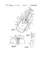
- FIG. 4is an end view of one of the indentors shown in FIGS. 1 and 3.
- FIG. 5is a fragmentary end view of the indentor shown in FIG. 4.
- FIG. 6is a fragmentary plan view of an array of indentors shown in FIGS. 3-5, and a crimped holder.
- FIG. 7is a perspective view of a brush contact holder crimped to the contact wires by the method and apparatus according to the present invention.
- FIG. 8is a transverse sectional view taken through the brush contact shown in FIG. 7 along Line 8--8.
- FIG. 9is a transverse sectional view taken through the brush contact shown in FIG. 7 taken along the line 9--9.
- FIG. 10is a transverse sectional view of a brush contact having one of the contact wires removed.
- FIG. 1shows the overall arrangement of the apparatus 10 used to implement the method according to the present invention. This includes a nest 12 having a generally cylindrical body portion 14.
- a radially convergent series of six bar-shaped indentors 16each including a sloping cam surface 18 on the projecting ends thereof protruding from beneath a nest cover 20 and overhanging a relief surface formed by a taper section 22 machined into the body section 14 beneath the ends of the indentors 16.
- Each of the indentors 16converge to a central region within which is disposed the brush contact 24 to be crimped as will be described hereinafter in further detail.
- the brush contact 24includes a holder 26 and a series of contact wires 28 each having one end received within the holder 26 and their free ends projecting upwardly from the region whereat the indentors 16 are located.
- the holderis made of a formable conductive material such as a plated thin metal sleeve.
- a camming sleeve 30 having an interior bore 32is slidably received over the body section 14.
- the camming sleeve 30is also formed with a complementarily-shaped internal shoulder 34 which is matched to the sloping external shoulder 32 formed on the body section 14 and adapted to come into mating engagement with the sloping cam surfaces 18 on the projecting ends of each of the indentors 16.
- a prebundler tube 36including a tubular portion 38 and a flange 40 secured to the protruding end portion.
- the tubular portionis received within a corresponding bore 42 formed into one end of the cam sleeve 30.
- the tubular portion 36is formed with an internal passage 44 having a chamfer 46 at the open end thereof disposed within the cam sleeve 30 and adapted to be advanced to enclose the contact wires 28 to maintain the wires in a tight bundle prior to crimping of the holder 26.
- the flange 40seats against an end face 48 of a pilot section 50 wherein the bore 42 is formed.
- the nest 12is formed with an external shoulder 52 which is adapted to abut an end face 54 of the cam sleeve 30 upon full advancing of the end sleeve 30 over the nest 14. This abutment or stop limits the advance of the cam sleeve 30 over the nest 14.
- indentors 16have each been cammed radially inwardly a predetermined distance sufficient to execute the crimping process on the brush holder 26.
- a nest cover 20is affixed to the nest 12 by a series of machine screws 56 and retains the indentors 16.
- FIG. 2shows the upper end of the nest portion 14 which is formed at one end with a reduced diameter boss portion 58 in turn formed with a series of corresponding slots 60 which are convergent towards a central bore 62.
- the bore 62receives the holder 26 with the contact wires 28 assembled thereinto, with a smaller diameter bore 64 receiving pin 66 of the holder 26 to locate the holder 26 aligned with the axis of the bore 62 and at the convergent axis of each of the inductors 16.
- FIG. 2One of the indentors 16 is removed in FIG. 2, showing the slot 60 for clarity.
- FIG. 3shows that each of the inductors 16 is comprised of an elongated bar shape having the camming surface 18 at one end and a forming tip 68 at the other.
- FIG. 4also shows the details of the forming end 68 which includes a flat 70 with an angular Vee-shaped primary crimping tip 72 separated by a recess 74 formed by a relief of the forward edge to the rear of each of the crimping surfaces 70 and 72.
- the tip 72comprises an edge which extends generally parallel to the length of the holder 26 when both are installed in the nest 14.
- a lower relief 76is also provided.
- the crimping processis primarily carried out by the Vee-shaped tip 72 in which each of the tip portions 72 is cammed simultaneously inwardly to crimp the holder 26, to create a series of crimp recesses 78.
- Recesses 78are axially extending valleys having sloping sides corresponding to the Vee-shaped tip 72 of each indentor 16, the valley sides extending along the length of the holder 26 for a portion of its length.
- Each of the crimp recesses 78extends between the adjacent pairs of the contact wires which are arranged about the central conduct wire, as will be described below in further detail. It has been discovered that a 120° included angle at the tip 72 produces very effectively the arrangement of the contact wires 28, and the advantageous crimping action.
- FIG. 7shows the completed brush contact 80 having the axially extending parallel crimp recesses 78 substantially aligned about the circumference of the holder 26, each of the crimp recesses 78 extending along the length of the holder 26.
- a series of flat sides 82are shaped into the holder 26 during the formation of the crimp recesses 78 by the flat-forming surface 70, the flats on the one end of the holder 26 which receives the contact wires 28 and is faced from the crimp recesses 78. It has been found that forming the holder 26 with the flat sides 82 tend to force the contact wires 28 into a tighter bundle.
- FIG. 8shows in section the resultant crimp pattern in which each of the contact wires 28 is forced into a symmetrical arrangement in intimate contact with the other contact wires 28. It has been discovered by the present inventors that the crimping method and apparatus described, causes the contact wires 28 to arrange themselves automatically in the symmetrical pattern shown in FIG. 8, with a central contact wire 28a with the remaining contacts wires 28b arranged peripherally about the central contact wire 28a, and each of them forced in to intimate contact with each other with very small or no voids in between.
- each of the crimp recesses 78extends between adjacent pairs of the peripheral contact wires 28a.
- the holder metal materialis also forced into intimate contact with each of the contact wires 28b with a complete absence of voids between the holder 26 and contact wires 28b, such that there is reliably established an electrical connection therebetween, and also reliably generating a retention force which is enhanced by the degree of contact between the holder material and the contact wires 28b.
- the outside diameter of the crimped holder 26is very consistent and the symmetry of the pattern affords a high degree of concentricity between the contact wire bundle and the holder outside diameter to greatly reduce the problem of interference between the shrouds and the outside diameter of the brush contact.
- FIG. 9shows that a series of flats 82 are so formed which overlie to be in contact with adjacent pairs of the peripheral contact wires 28b. It has been discovered that crimping therein of these flats 82 at one end of the holder 26 provides for a tighter bundle by providing a support for the contact wires immediately adjacent the end of the holder 26 providing a tighter bundle and effectively less contact resistance across mated brush contacts.
- FIG. 10shows that the intimate contact produced by the crimping process has been found to allow a missing peripheral contact wire 28b as shown in this FIGURE while still retaining a tight connection with the remaining peripheral wires 28b.
- the method and apparatus according to the present inventionproduces a brush contact of superior construction having improved characteristics affording the advantages as set forth above.
- other numbers of contact wiresmay be crimped in which the contact wires arrange themselves about the periphery of a central contact wire by the use of a corresponding plurality of indentors having angularly shaped forming tips with the corresponding number of indentors equal to the number of contact wires arranged about the periphery of the central contact wire.
Landscapes
- Engineering & Computer Science (AREA)
- Manufacturing & Machinery (AREA)
- Manufacturing Of Electrical Connectors (AREA)
Abstract
Description
Claims (5)
Priority Applications (7)
| Application Number | Priority Date | Filing Date | Title |
|---|---|---|---|
| US06/319,496US4426128A (en) | 1981-11-09 | 1981-11-09 | Brush contacts |
| CA000405730ACA1207861A (en) | 1981-11-09 | 1982-06-22 | Method and apparatus for crimping brush contacts |
| JP57194490AJPS5885289A (en) | 1981-11-09 | 1982-11-05 | Method and device for caulking brush contact wire |
| DE8282402050TDE3269691D1 (en) | 1981-11-09 | 1982-11-08 | Apparatus for crimping brush contacts |
| EP82402050AEP0079289B1 (en) | 1981-11-09 | 1982-11-08 | Apparatus for crimping brush contacts |
| US06/527,591US4509255A (en) | 1981-11-09 | 1983-08-29 | Apparatus for crimping brush contacts |
| CA000476834ACA1207134A (en) | 1981-11-09 | 1985-03-18 | Apparatus for crimping brush contacts |
Applications Claiming Priority (1)
| Application Number | Priority Date | Filing Date | Title |
|---|---|---|---|
| US06/319,496US4426128A (en) | 1981-11-09 | 1981-11-09 | Brush contacts |
Related Child Applications (1)
| Application Number | Title | Priority Date | Filing Date |
|---|---|---|---|
| US06/527,591DivisionUS4509255A (en) | 1981-11-09 | 1983-08-29 | Apparatus for crimping brush contacts |
Publications (1)
| Publication Number | Publication Date |
|---|---|
| US4426128Atrue US4426128A (en) | 1984-01-17 |
Family
ID=23242480
Family Applications (1)
| Application Number | Title | Priority Date | Filing Date |
|---|---|---|---|
| US06/319,496Expired - LifetimeUS4426128A (en) | 1981-11-09 | 1981-11-09 | Brush contacts |
Country Status (5)
| Country | Link |
|---|---|
| US (1) | US4426128A (en) |
| EP (1) | EP0079289B1 (en) |
| JP (1) | JPS5885289A (en) |
| CA (1) | CA1207861A (en) |
| DE (1) | DE3269691D1 (en) |
Cited By (2)
| Publication number | Priority date | Publication date | Assignee | Title |
|---|---|---|---|---|
| US4974314A (en)* | 1989-09-29 | 1990-12-04 | Thomas & Betts Corporation | Crimping tool having spring loaded contact locator |
| US20090203253A1 (en)* | 2008-02-12 | 2009-08-13 | Chaojiong Zhang | Contact Terminal With Self-Adjusting Contact Surface |
Families Citing this family (2)
| Publication number | Priority date | Publication date | Assignee | Title |
|---|---|---|---|---|
| US20150085420A1 (en)* | 2013-09-26 | 2015-03-26 | Inpro/Seal Llc | Conductive Assembly |
| CN105977679B (en)* | 2016-05-20 | 2019-02-15 | 中航光电科技股份有限公司 | An electrical connector contact piece and a preparation tool for the electrical connector contact piece |
Citations (22)
| Publication number | Priority date | Publication date | Assignee | Title |
|---|---|---|---|---|
| US2280352A (en) | 1940-02-01 | 1942-04-21 | H A Douglas Mfg Co | Method of swaging |
| US2314884A (en) | 1940-05-01 | 1943-03-30 | Klein Peter | Connector |
| US2480280A (en) | 1945-09-24 | 1949-08-30 | Thomas & Betts Corp | Electric connector |
| US2622314A (en) | 1947-07-07 | 1952-12-23 | Thomas & Betts Corp | Method of forming spliced sector cables |
| US2803695A (en) | 1951-05-03 | 1957-08-20 | Amp Inc | Closed end connector |
| DE1018123B (en) | 1953-05-12 | 1957-10-24 | Siemens Ag | Method for producing a mechanical and electrical connection between an aluminum tubular rivet or aluminum hollow pin and a connecting wire inserted into the hollow rivet or hollow pin |
| US2816276A (en) | 1954-01-05 | 1957-12-10 | Amp Inc | Electrical connectors, method and apparatus |
| US2921618A (en) | 1956-05-16 | 1960-01-19 | Amp Inc | Indenting dies for electrical terminals |
| US2927150A (en) | 1955-12-20 | 1960-03-01 | Aircraft Marine Prod Inc | Insulation piercing crimp |
| US3006983A (en) | 1959-02-11 | 1961-10-31 | Anderson Electric Corp | Universal compression connector and method of crimping same |
| CA675592A (en) | 1963-12-10 | Edwin Floyd, Jr. | Connector crimps and methods and apparatus | |
| US3185762A (en) | 1962-12-21 | 1965-05-25 | Anderson Electric Corp | Cable connectors |
| US3255430A (en) | 1964-12-07 | 1966-06-07 | New Twist Connector Corp | Spirally wound pin connector |
| DE1221726B (en) | 1963-09-07 | 1966-07-28 | Patra Patent Treuhand | Electrical clamping connection of a tubular contact pin with an electrical conductor and method for producing this clamping connection |
| US3451116A (en) | 1966-09-27 | 1969-06-24 | Walter A Shields | Machine for crimping a ferrule to a hypodermic needle |
| US3511075A (en) | 1966-10-11 | 1970-05-12 | Barogenics Inc | Metalworking method of securing a sleeve to a core |
| US4120556A (en) | 1976-03-01 | 1978-10-17 | The Bendix Corporation | Electrical contact assembly |
| US4206958A (en) | 1978-03-27 | 1980-06-10 | The Bendix Corporation | Electrical conductor having an integral electrical contact |
| US4242790A (en) | 1978-09-28 | 1981-01-06 | The Bendix Corporation | Method of making an electrical connector contact |
| US4253234A (en) | 1978-12-26 | 1981-03-03 | The Bendix Corporation | Method of making electrical contact |
| US4272150A (en) | 1979-09-24 | 1981-06-09 | The Bendix Corporation | Electrical contact for an electrical connector |
| US4312125A (en) | 1979-12-03 | 1982-01-26 | The Bendix Corporation | Method and apparatus for automatically inserting an electrical contact into an electrical connector |
Family Cites Families (3)
| Publication number | Priority date | Publication date | Assignee | Title |
|---|---|---|---|---|
| JPS5627998A (en)* | 1979-08-16 | 1981-03-18 | Matsushita Electric Industrial Co Ltd | Device for mounting circuit element |
| US4357742A (en)* | 1980-05-27 | 1982-11-09 | The Bendix Corporation | Electric brush contact forming apparatus |
| JPS5758288U (en)* | 1980-09-22 | 1982-04-06 |
- 1981
- 1981-11-09USUS06/319,496patent/US4426128A/ennot_activeExpired - Lifetime
- 1982
- 1982-06-22CACA000405730Apatent/CA1207861A/ennot_activeExpired
- 1982-11-05JPJP57194490Apatent/JPS5885289A/enactiveGranted
- 1982-11-08DEDE8282402050Tpatent/DE3269691D1/ennot_activeExpired
- 1982-11-08EPEP82402050Apatent/EP0079289B1/ennot_activeExpired
Patent Citations (22)
| Publication number | Priority date | Publication date | Assignee | Title |
|---|---|---|---|---|
| CA675592A (en) | 1963-12-10 | Edwin Floyd, Jr. | Connector crimps and methods and apparatus | |
| US2280352A (en) | 1940-02-01 | 1942-04-21 | H A Douglas Mfg Co | Method of swaging |
| US2314884A (en) | 1940-05-01 | 1943-03-30 | Klein Peter | Connector |
| US2480280A (en) | 1945-09-24 | 1949-08-30 | Thomas & Betts Corp | Electric connector |
| US2622314A (en) | 1947-07-07 | 1952-12-23 | Thomas & Betts Corp | Method of forming spliced sector cables |
| US2803695A (en) | 1951-05-03 | 1957-08-20 | Amp Inc | Closed end connector |
| DE1018123B (en) | 1953-05-12 | 1957-10-24 | Siemens Ag | Method for producing a mechanical and electrical connection between an aluminum tubular rivet or aluminum hollow pin and a connecting wire inserted into the hollow rivet or hollow pin |
| US2816276A (en) | 1954-01-05 | 1957-12-10 | Amp Inc | Electrical connectors, method and apparatus |
| US2927150A (en) | 1955-12-20 | 1960-03-01 | Aircraft Marine Prod Inc | Insulation piercing crimp |
| US2921618A (en) | 1956-05-16 | 1960-01-19 | Amp Inc | Indenting dies for electrical terminals |
| US3006983A (en) | 1959-02-11 | 1961-10-31 | Anderson Electric Corp | Universal compression connector and method of crimping same |
| US3185762A (en) | 1962-12-21 | 1965-05-25 | Anderson Electric Corp | Cable connectors |
| DE1221726B (en) | 1963-09-07 | 1966-07-28 | Patra Patent Treuhand | Electrical clamping connection of a tubular contact pin with an electrical conductor and method for producing this clamping connection |
| US3255430A (en) | 1964-12-07 | 1966-06-07 | New Twist Connector Corp | Spirally wound pin connector |
| US3451116A (en) | 1966-09-27 | 1969-06-24 | Walter A Shields | Machine for crimping a ferrule to a hypodermic needle |
| US3511075A (en) | 1966-10-11 | 1970-05-12 | Barogenics Inc | Metalworking method of securing a sleeve to a core |
| US4120556A (en) | 1976-03-01 | 1978-10-17 | The Bendix Corporation | Electrical contact assembly |
| US4206958A (en) | 1978-03-27 | 1980-06-10 | The Bendix Corporation | Electrical conductor having an integral electrical contact |
| US4242790A (en) | 1978-09-28 | 1981-01-06 | The Bendix Corporation | Method of making an electrical connector contact |
| US4253234A (en) | 1978-12-26 | 1981-03-03 | The Bendix Corporation | Method of making electrical contact |
| US4272150A (en) | 1979-09-24 | 1981-06-09 | The Bendix Corporation | Electrical contact for an electrical connector |
| US4312125A (en) | 1979-12-03 | 1982-01-26 | The Bendix Corporation | Method and apparatus for automatically inserting an electrical contact into an electrical connector |
Cited By (3)
| Publication number | Priority date | Publication date | Assignee | Title |
|---|---|---|---|---|
| US4974314A (en)* | 1989-09-29 | 1990-12-04 | Thomas & Betts Corporation | Crimping tool having spring loaded contact locator |
| US20090203253A1 (en)* | 2008-02-12 | 2009-08-13 | Chaojiong Zhang | Contact Terminal With Self-Adjusting Contact Surface |
| US7614907B2 (en) | 2008-02-12 | 2009-11-10 | Chaojiong Zhang | Contact terminal with self-adjusting contact surface |
Also Published As
| Publication number | Publication date |
|---|---|
| EP0079289A1 (en) | 1983-05-18 |
| EP0079289B1 (en) | 1986-03-05 |
| CA1207861A (en) | 1986-07-15 |
| JPH0363188B2 (en) | 1991-09-30 |
| DE3269691D1 (en) | 1986-04-10 |
| JPS5885289A (en) | 1983-05-21 |
Similar Documents
| Publication | Publication Date | Title |
|---|---|---|
| JP3045300B2 (en) | Female contact of electrical connector and method of providing female contact of the electrical connector | |
| JP2617153B2 (en) | Coaxial cable connector | |
| US4734064A (en) | Electrical socket contact with convex engaging tines | |
| US5041009A (en) | Daisy chain connector and method | |
| US4784623A (en) | Mass terminable flat flexible cable to pin connector | |
| US4035049A (en) | Universal solderless termination system | |
| US6734359B2 (en) | Wire connecting structure and connecting method | |
| US4040702A (en) | Solderless termination system | |
| US4253234A (en) | Method of making electrical contact | |
| EP1191631B1 (en) | Method of connecting terminal to wire | |
| US4836803A (en) | Wire holding device in an electrical connector | |
| US4442316A (en) | Crimp connector for electrical wires | |
| EP0090850A1 (en) | Method and apparatus for making fork contacts | |
| US4426128A (en) | Brush contacts | |
| JPH04369515A (en) | Wire insert molding method | |
| JP2876146B2 (en) | Receptacle type contact | |
| US4509255A (en) | Apparatus for crimping brush contacts | |
| EP0356025B1 (en) | Daisy chain connector and method | |
| EP0026117B1 (en) | Electrical contact for an electrical connector and method of making same | |
| GB2083295A (en) | Electric connector for flat cable | |
| US3209311A (en) | Connector | |
| CA1207134A (en) | Apparatus for crimping brush contacts | |
| US5430254A (en) | Reverse crimp connector | |
| US4804344A (en) | Cable connector and crimping tool therefor | |
| US3980378A (en) | Clip connection |
Legal Events
| Date | Code | Title | Description |
|---|---|---|---|
| AS | Assignment | Owner name:BENDIX CORPORATION, THE, BENDIX CENTER, SOUTHFIELD Free format text:ASSIGNMENT OF ASSIGNORS INTEREST.;ASSIGNORS:COSTELLO, SAMUEL J.;SOHNE, ERIC R.;REEL/FRAME:003951/0310 Effective date:19811030 Owner name:BENDIX CORPORATION, THE, A CORP. OF DE., MICHIGAN Free format text:ASSIGNMENT OF ASSIGNORS INTEREST;ASSIGNORS:COSTELLO, SAMUEL J.;SOHNE, ERIC R.;REEL/FRAME:003951/0310 Effective date:19811030 Owner name:BENDIX CORPORATION, THE, MICHIGAN Free format text:ASSIGNMENT OF ASSIGNORS INTEREST;ASSIGNORS:COSTELLO, SAMUEL J.;SOHNE, ERIC R.;REEL/FRAME:003951/0310 Effective date:19811030 | |
| STCF | Information on status: patent grant | Free format text:PATENTED CASE | |
| FEPP | Fee payment procedure | Free format text:PAYOR NUMBER ASSIGNED (ORIGINAL EVENT CODE: ASPN); ENTITY STATUS OF PATENT OWNER: LARGE ENTITY | |
| MAFP | Maintenance fee payment | Free format text:PAYMENT OF MAINTENANCE FEE, 4TH YEAR, PL 96-517 (ORIGINAL EVENT CODE: M170); ENTITY STATUS OF PATENT OWNER: LARGE ENTITY Year of fee payment:4 | |
| AS | Assignment | Owner name:ALLIED CORPORATION, A CORP. OF NY Free format text:MERGER;ASSIGNOR:BENDIX CORPORATION, THE,;REEL/FRAME:004765/0709 Effective date:19850401 Owner name:CANADIAN IMPERIAL BANK OF COMMERCE, NEW YORK AGENC Free format text:SECURITY INTEREST;ASSIGNOR:AMPHENOL CORPORATION;REEL/FRAME:004879/0030 Effective date:19870515 | |
| AS | Assignment | Owner name:AMPHENOL CORPORATION, LISLE, ILLINOIS A CORP. OF D Free format text:ASSIGNMENT OF ASSIGNORS INTEREST.;ASSIGNOR:ALLIED CORPORATION, A CORP. OF NY;REEL/FRAME:004844/0850 Effective date:19870602 Owner name:AMPHENOL CORPORATION, A CORP. OF DE, ILLINOIS Free format text:ASSIGNMENT OF ASSIGNORS INTEREST;ASSIGNOR:ALLIED CORPORATION, A CORP. OF NY;REEL/FRAME:004844/0850 Effective date:19870602 | |
| MAFP | Maintenance fee payment | Free format text:PAYMENT OF MAINTENANCE FEE, 8TH YEAR, PL 96-517 (ORIGINAL EVENT CODE: M171); ENTITY STATUS OF PATENT OWNER: LARGE ENTITY Year of fee payment:8 | |
| AS | Assignment | Owner name:BANKERS TRUST COMPANY, AS AGENT Free format text:SECURITY INTEREST;ASSIGNOR:AMPHENOL CORPORATION, A CORPORATION OF DE;REEL/FRAME:006035/0283 Effective date:19911118 | |
| AS | Assignment | Owner name:AMPHENOL CORPORATION A CORP. OF DELAWARE Free format text:RELEASED BY SECURED PARTY;ASSIGNOR:CANADIAN IMPERIAL BANK OF COMMERCE;REEL/FRAME:006147/0887 Effective date:19911114 | |
| AS | Assignment | Owner name:AMPHENOL CORPORATION, CONNECTICUT Free format text:RELEASE BY SECURED PARTY;ASSIGNOR:BANKERS TRUST COMPANY;REEL/FRAME:007317/0148 Effective date:19950104 | |
| MAFP | Maintenance fee payment | Free format text:PAYMENT OF MAINTENANCE FEE, 12TH YEAR, LARGE ENTITY (ORIGINAL EVENT CODE: M185); ENTITY STATUS OF PATENT OWNER: LARGE ENTITY Year of fee payment:12 | |
| FEPP | Fee payment procedure | Free format text:PAYOR NUMBER ASSIGNED (ORIGINAL EVENT CODE: ASPN); ENTITY STATUS OF PATENT OWNER: LARGE ENTITY Free format text:PAYER NUMBER DE-ASSIGNED (ORIGINAL EVENT CODE: RMPN); ENTITY STATUS OF PATENT OWNER: LARGE ENTITY |