US4425928A - Liquid discharge apparatus - Google Patents
Liquid discharge apparatusDownload PDFInfo
- Publication number
- US4425928A US4425928AUS06/312,562US31256281AUS4425928AUS 4425928 AUS4425928 AUS 4425928AUS 31256281 AUS31256281 AUS 31256281AUS 4425928 AUS4425928 AUS 4425928A
- Authority
- US
- United States
- Prior art keywords
- pipe
- overflow
- overflow pipes
- liquid
- pipes
- Prior art date
- Legal status (The legal status is an assumption and is not a legal conclusion. Google has not performed a legal analysis and makes no representation as to the accuracy of the status listed.)
- Expired - Fee Related
Links
Images


Classifications
- B—PERFORMING OPERATIONS; TRANSPORTING
- B21—MECHANICAL METAL-WORKING WITHOUT ESSENTIALLY REMOVING MATERIAL; PUNCHING METAL
- B21B—ROLLING OF METAL
- B21B45/00—Devices for surface or other treatment of work, specially combined with or arranged in, or specially adapted for use in connection with, metal-rolling mills
- B21B45/02—Devices for surface or other treatment of work, specially combined with or arranged in, or specially adapted for use in connection with, metal-rolling mills for lubricating, cooling, or cleaning
- B21B45/0203—Cooling
- B21B45/0209—Cooling devices, e.g. using gaseous coolants
- B21B45/0215—Cooling devices, e.g. using gaseous coolants using liquid coolants, e.g. for sections, for tubes
- B21B45/0218—Cooling devices, e.g. using gaseous coolants using liquid coolants, e.g. for sections, for tubes for strips, sheets, or plates
- B—PERFORMING OPERATIONS; TRANSPORTING
- B05—SPRAYING OR ATOMISING IN GENERAL; APPLYING FLUENT MATERIALS TO SURFACES, IN GENERAL
- B05B—SPRAYING APPARATUS; ATOMISING APPARATUS; NOZZLES
- B05B1/00—Nozzles, spray heads or other outlets, with or without auxiliary devices such as valves, heating means
- B05B1/36—Outlets for discharging by overflow
- B—PERFORMING OPERATIONS; TRANSPORTING
- B05—SPRAYING OR ATOMISING IN GENERAL; APPLYING FLUENT MATERIALS TO SURFACES, IN GENERAL
- B05B—SPRAYING APPARATUS; ATOMISING APPARATUS; NOZZLES
- B05B12/00—Arrangements for controlling delivery; Arrangements for controlling the spray area
- Y—GENERAL TAGGING OF NEW TECHNOLOGICAL DEVELOPMENTS; GENERAL TAGGING OF CROSS-SECTIONAL TECHNOLOGIES SPANNING OVER SEVERAL SECTIONS OF THE IPC; TECHNICAL SUBJECTS COVERED BY FORMER USPC CROSS-REFERENCE ART COLLECTIONS [XRACs] AND DIGESTS
- Y10—TECHNICAL SUBJECTS COVERED BY FORMER USPC
- Y10T—TECHNICAL SUBJECTS COVERED BY FORMER US CLASSIFICATION
- Y10T137/00—Fluid handling
- Y10T137/8593—Systems
- Y10T137/86381—Head-establishing standpipe or expansion chamber [e.g., surge tanks]
Definitions
- the present inventionrelates to an improvement in controlling the quantity of fluid delivered to a header and discharged in turn by the header to an object to be treated by the fluid. While the invention is considered to have a wide range of applications, for the purpose of explanation, it will be discussed as applied to the cooling of hot strip while being rolled or immediately after rolling in a rolling mill.
- an object of the present inventionto provide an improved liquid discharge apparatus that will produce the required volumetric output with the necessary flexibility and reliability but which will not include a variable flow control, but instead, employes a system giving a full flow or one or more lesser fractional flow rates controlled by an on-off system of control.
- It is a still further object of the present invention to provide a water discharge system for cooling hot rolled steel stripincluding a header for delivering water, a water supply system for the header, two fixed overflow pipes, one capable of producing a full flow volumetric capacity and the other half flow volumetric capacity of the water delivered by the header, and a valve for bringing into operation one or the other of said overflow pipes.
- FIG. 1is a plan view of a multi-overflow pipe strip cooling system provided for the runout section of a hot strip mill in accordance with the teachings of the present invention
- FIG. 2is an elevational sectional view taken on lines 2--2 of FIG. 1;
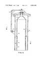
- FIG. 3is an elevational view of a second embodiment of the present invention.
- FIG. 4is a sectional view taken on lines 4--4 of FIG. 3.
- FIGS. 1 and 2there is illustrated a strip cooling unit for a runout table zone of a hot strip rolling mill, not shown.
- Several of the horizontally arranged table rollers of the runout zoneare shown in phantom at 10. It should be initially appreciated that the runout zone will be made up of a relatively large number of these units which take the form of several horizontally arranged banks of headers.
- One of the important features of the present inventionwhich will be more fully explained later, reside in the advantage realized by the invention in operating one or more of the banks at 100% of its maximum cooling capacity, and the other header banks at 50% of the maximum cooling capacity, thereby reducing the delta temperature variation of the strip at the downcoiler, not shown, by 50%.
- FIG. 1there is shown a number of upper strip cooling headers 12 which can be constructed in a well known manner to deliver the necessary quantity (GPM) of coolant to the upper surface to the strip as required by the mill.
- This particular headeris designed to deliver a uniform cross-sectional curtain wall of water from a substantial distance above the strip.
- a similar header systemis provided for applying water to the lower surface of the strip. While FIG. 1 only shows a number of upper headers 12, FIG. 2 indicates that the system includes a like number of bottom strip cooling headers, in the showing of input lines 14, the input lines of the top header being indicated at 16.
- Each group or banks of headersare connected to supply manifold 18 and 20, both of which are shown in FIGS. 1 and 2. Addressing our first to the upper strip cooling headers 12 and their supply manifold 18, at the left side as one views FIGS. 1 and 2, the supply manifold 18 is connected to a supply line, not shown, and at the right to an elbow 22 from where the water is fed to two stationary or fixed overflow pipes.
- the waterenters the first of the two fixedly vertically arranged overflow pipes, namely pipe 24, the effective hydraulic head of which has been designed to provide the required volume (GPM) of water, i.e., 100% of the capacity of the header bank.
- the overflow pipe 24has a central cylindrical section 26 into which the water from the manifold 18 enters and which will be filled under certain circumstances until it overflows at the top thereof. When this occurs, the overflowing water will flow around the outside of the cylindrical section 26, but inside the outer section 28 of the overflow pipe 24, and fall to the bottom of the pipe and be conveyed away by drain piping 30. In this area it will be noticed a base 32 is provided to support the overflow pipe 24.
- the second fixedly mounted overflow pipe 34is mounted to the left of the overflow pipe 24 as one views FIG. 2, and is associated with an electrically operated two-way valve 36 mounted in a line 38 that runs between the two overflow pipes 24 and 34.
- the construction of overflow pipe 34is generally similar to that of the overflow pipe 24, having a central section 40 into which water is fed and allowed to rise to form an hydraulic head of water at a predictable height determined to be one-half of the hydraulic head of the overflow pipe 24, thus giving a quick and accurate option of delivering water to the headers 12 at 100% or 50% of the maximum GPM capacity of the system.
- the effective hydraulic heads of the two overflow pipeswill control the volume of water delivered to and by the headers.
- the construction and operation of the valve 36is such that when the valve is closed water will be prevented from passing to the overflow pipe 34, and when open, overflow pipe 34 will receive water so that the water that would pass into overflow pipe 24 will be maintained at the same height or head as the water head of pipe 34.
- FIG. 2there is shown a part of the electrical control operating mechanism 42 for the valve 36.
- the drain for the overflow pipe 34is provided at the bottom of the overflow pipe in the form of a pipe 44, which empties into the drain portion of the overflow pipe 24 as shown in FIG. 2.
- the present inventioncan take the form of a header-dual overflow pipe arrangement that can be employed between the stands of the rolling mill wherein one or more headers can be utilized.
- a dual overflow pipe systemhas been described above which will give the desired fineness of control for generally all hot strip mill applications presently known, should a still finer degree of control be desirable, additional overflow pipes can be utilized allowing finer degree or smaller fractional control to be obtained.
- FIGS. 3 and 4illustrate a second embodiment of the present invention.
- a combined constructioncan be employed.
- a portion of overflow pipe 54is shown having a central cylindrical member 56 which at the top is open to allow water to overflow and return to drain, not shown, between the inside member 54 and the outside of the member 56.
- the member 56 at its bottomhas a stationary portion 58 which rotatably supports the upper portion thereof 60.
- Both of these portions 58 and 60are provided with a series of complementary openings 62 and 64, respectively, which when the openings 64 are rotated to allow the openings to align themselves, water is allowed to overflow at the level of the openings instead of at the top of the portion 60, thus allowing the operational creation of two different hydraulic heights or heads of water in the overflow pipe 54.
- FIG. 4the openings of the portion 60 are shown in their closed position.
- the portion 60is rotated by a handle 66 connected to the top of a shaft 68 and a bearing assembly 70, the shaft being integrally connected to the upper portion 60 of the overflow pipe 54.
- a locking pinis provided at 72 to maintain the openings 64 in the desired position.
Landscapes
- Engineering & Computer Science (AREA)
- Mechanical Engineering (AREA)
- Control Of Metal Rolling (AREA)
- Steam Or Hot-Water Central Heating Systems (AREA)
- Heat Treatments In General, Especially Conveying And Cooling (AREA)
- Heat Treatment Of Strip Materials And Filament Materials (AREA)
- Nozzles (AREA)
Abstract
Description
Claims (12)
Priority Applications (5)
| Application Number | Priority Date | Filing Date | Title |
|---|---|---|---|
| US06/312,562US4425928A (en) | 1981-10-19 | 1981-10-19 | Liquid discharge apparatus |
| GB08223317AGB2108028B (en) | 1981-10-19 | 1982-08-13 | Liquid discharge apparatus |
| CA000412869ACA1189325A (en) | 1981-10-19 | 1982-10-05 | Liquid discharge apparatus |
| DE8282401912TDE3275164D1 (en) | 1981-10-19 | 1982-10-19 | Liquid distribution apparatus |
| EP82401912AEP0078199B1 (en) | 1981-10-19 | 1982-10-19 | Liquid distribution apparatus |
Applications Claiming Priority (1)
| Application Number | Priority Date | Filing Date | Title |
|---|---|---|---|
| US06/312,562US4425928A (en) | 1981-10-19 | 1981-10-19 | Liquid discharge apparatus |
Publications (1)
| Publication Number | Publication Date |
|---|---|
| US4425928Atrue US4425928A (en) | 1984-01-17 |
Family
ID=23212037
Family Applications (1)
| Application Number | Title | Priority Date | Filing Date |
|---|---|---|---|
| US06/312,562Expired - Fee RelatedUS4425928A (en) | 1981-10-19 | 1981-10-19 | Liquid discharge apparatus |
Country Status (5)
| Country | Link |
|---|---|
| US (1) | US4425928A (en) |
| EP (1) | EP0078199B1 (en) |
| CA (1) | CA1189325A (en) |
| DE (1) | DE3275164D1 (en) |
| GB (1) | GB2108028B (en) |
Cited By (1)
| Publication number | Priority date | Publication date | Assignee | Title |
|---|---|---|---|---|
| US20110186282A1 (en)* | 2008-07-29 | 2011-08-04 | Siemens Vai Metals Technologies S.A.S. | Method and device for adjusting the cooling and energy recovery of a steel strip in an annealing or galvanization phase |
Citations (4)
| Publication number | Priority date | Publication date | Assignee | Title |
|---|---|---|---|---|
| US1998192A (en) | 1933-12-22 | 1935-04-16 | Arthur B Haswell | Means for guiding and cooling rolled metal |
| US3299900A (en) | 1965-03-25 | 1967-01-24 | United Eng Foundry Co | Strip cooling system |
| US4149703A (en) | 1978-01-31 | 1979-04-17 | Drever Company | Apparatus for quenching a heated metal plate |
| US4367785A (en) | 1981-02-09 | 1983-01-11 | Logic Devices, Inc. | Liquid circulation method and apparatus |
Family Cites Families (3)
| Publication number | Priority date | Publication date | Assignee | Title |
|---|---|---|---|---|
| US2625175A (en)* | 1949-05-31 | 1953-01-13 | Maloney Crawford Tank & Mfg Co | Siphon box |
| FR1282158A (en)* | 1960-12-09 | 1962-01-19 | Improvements to sizing installations | |
| US3294107A (en)* | 1964-03-02 | 1966-12-27 | Jones & Laughlin Steel Company | Apparatus for cooling hot bodies |
- 1981
- 1981-10-19USUS06/312,562patent/US4425928A/ennot_activeExpired - Fee Related
- 1982
- 1982-08-13GBGB08223317Apatent/GB2108028B/ennot_activeExpired
- 1982-10-05CACA000412869Apatent/CA1189325A/ennot_activeExpired
- 1982-10-19EPEP82401912Apatent/EP0078199B1/ennot_activeExpired
- 1982-10-19DEDE8282401912Tpatent/DE3275164D1/ennot_activeExpired
Patent Citations (4)
| Publication number | Priority date | Publication date | Assignee | Title |
|---|---|---|---|---|
| US1998192A (en) | 1933-12-22 | 1935-04-16 | Arthur B Haswell | Means for guiding and cooling rolled metal |
| US3299900A (en) | 1965-03-25 | 1967-01-24 | United Eng Foundry Co | Strip cooling system |
| US4149703A (en) | 1978-01-31 | 1979-04-17 | Drever Company | Apparatus for quenching a heated metal plate |
| US4367785A (en) | 1981-02-09 | 1983-01-11 | Logic Devices, Inc. | Liquid circulation method and apparatus |
Cited By (2)
| Publication number | Priority date | Publication date | Assignee | Title |
|---|---|---|---|---|
| US20110186282A1 (en)* | 2008-07-29 | 2011-08-04 | Siemens Vai Metals Technologies S.A.S. | Method and device for adjusting the cooling and energy recovery of a steel strip in an annealing or galvanization phase |
| US8506877B2 (en)* | 2008-07-29 | 2013-08-13 | Siemens Vai Metals Technologies Sas | Method and device for adjusting the cooling and energy recovery of a steel strip in an annealing or galvanization phase |
Also Published As
| Publication number | Publication date |
|---|---|
| DE3275164D1 (en) | 1987-02-26 |
| EP0078199A3 (en) | 1984-01-11 |
| CA1189325A (en) | 1985-06-25 |
| GB2108028B (en) | 1985-08-14 |
| EP0078199A2 (en) | 1983-05-04 |
| EP0078199B1 (en) | 1987-01-21 |
| GB2108028A (en) | 1983-05-11 |
Similar Documents
| Publication | Publication Date | Title |
|---|---|---|
| CN101291750B (en) | Process and apparatus for producing metal strip | |
| US3779054A (en) | Coolant control for hot strip mill | |
| DE2703169C2 (en) | Process for the production of metal powder and device for carrying out the process | |
| EP2643109B2 (en) | Method and device for the controlled secondary cooling of a continuous casting installation | |
| DE102009053073A1 (en) | Method and cooling device for cooling the rolls of a roll stand | |
| KR20130109156A (en) | Energy- and yield-optimized method and plant for producing hot steel strip | |
| CN105813779A (en) | Steel plant with multiple co-rolling line and corresponding method of production | |
| US4425928A (en) | Liquid discharge apparatus | |
| EP3594554A1 (en) | Device for supercooling of liquefied gases | |
| EP0041941B1 (en) | Process for regulating the through-flow of a cooling bunker | |
| DE4138655C2 (en) | Outflow regulator for tundish | |
| WO1988009230A1 (en) | Coolant flow control | |
| US2056433A (en) | Rolling mill | |
| US3941611A (en) | Apparatus for cooling strip like material | |
| US2150340A (en) | Cooling rolling mill | |
| US690917A (en) | Apparatus for continuous rolling direct from fluid metal. | |
| WO2015028370A1 (en) | Method and apparatus for controlling the temperature of rolls | |
| US11110511B2 (en) | Continuous caster roll having a spiral fluted axle | |
| JPS62253710A (en) | Apparatus for cooling moving metal product | |
| DE2149941A1 (en) | Continuous roll metal casting mould - for metal strip | |
| US406945A (en) | Apparatus for making sheet metal | |
| DE10295852B4 (en) | Device for controllable cooling of rolling stock | |
| DE10160739C2 (en) | Method and device for cooling the copper plates of a continuous casting mold for liquid metals, in particular for liquid steel | |
| JP7318023B2 (en) | Cooling section with valve and pressure vessel to prevent pressure shock | |
| CH536151A (en) | Continuous roll metal casting mould - for metal strip |
Legal Events
| Date | Code | Title | Description |
|---|---|---|---|
| AS | Assignment | Owner name:WEAN UNITED, INC., PITTSBURGH, PA., AN OH CORP Free format text:ASSIGNMENT OF ASSIGNORS INTEREST.;ASSIGNORS:GREENBERGER, JOSEPH I.;KOHRING, FREDERICK C.;REEL/FRAME:004176/0065 Effective date:19820927 Owner name:WEAN UNITED, INC., AN OH CORP, PENNSYLVANIA Free format text:ASSIGNMENT OF ASSIGNORS INTEREST;ASSIGNORS:GREENBERGER, JOSEPH I.;KOHRING, FREDERICK C.;REEL/FRAME:004176/0065 Effective date:19820927 | |
| AS | Assignment | Owner name:PITTSBURGH NATIONAL BANK Free format text:SECURITY INTEREST;ASSIGNOR:WEAN UNITED, INC., A CORP.OF OH;REEL/FRAME:004458/0765 Effective date:19850610 | |
| MAFP | Maintenance fee payment | Free format text:PAYMENT OF MAINTENANCE FEE, 4TH YEAR, PL 96-517 (ORIGINAL EVENT CODE: M170); ENTITY STATUS OF PATENT OWNER: LARGE ENTITY Year of fee payment:4 | |
| AS | Assignment | Owner name:PITTSBURGH NATIONAL BANK Free format text:SECURITY INTEREST;ASSIGNOR:WEAN UNITED, INC., A CORP. OH.;REEL/FRAME:004792/0307 Effective date:19860630 Owner name:PITTSBURGH NATIONAL BANK,PENNSYLVANIA Free format text:SECURITY INTEREST;ASSIGNOR:WEAN UNITED, INC., A CORP. OH.;REEL/FRAME:004792/0307 Effective date:19860630 | |
| AS | Assignment | Owner name:WEAN UNITED, INC. Free format text:RELEASED BY SECURED PARTY;ASSIGNOR:PITTSBURGH NATIONAL BANK;REEL/FRAME:004925/0218 Effective date:19880509 | |
| AS | Assignment | Owner name:UNITED ENGINEERING ROLLING MILLS, INC. Free format text:ASSIGNMENT OF ASSIGNORS INTEREST.;ASSIGNOR:WEAN INCORPORATED;REEL/FRAME:004920/0256 Effective date:19880610 | |
| AS | Assignment | Owner name:UNITED ENGINEERING, INC. Free format text:CHANGE OF NAME;ASSIGNOR:UNITED ENGINEERING ROLLING MILLS, INC.;REEL/FRAME:005285/0209 Effective date:19900425 | |
| FEPP | Fee payment procedure | Free format text:PAYOR NUMBER ASSIGNED (ORIGINAL EVENT CODE: ASPN); ENTITY STATUS OF PATENT OWNER: LARGE ENTITY | |
| MAFP | Maintenance fee payment | Free format text:PAYMENT OF MAINTENANCE FEE, 8TH YEAR, PL 96-517 (ORIGINAL EVENT CODE: M171); ENTITY STATUS OF PATENT OWNER: LARGE ENTITY Year of fee payment:8 | |
| FEPP | Fee payment procedure | Free format text:MAINTENANCE FEE REMINDER MAILED (ORIGINAL EVENT CODE: REM.); ENTITY STATUS OF PATENT OWNER: LARGE ENTITY | |
| LAPS | Lapse for failure to pay maintenance fees | ||
| FP | Lapsed due to failure to pay maintenance fee | Effective date:19960117 | |
| STCH | Information on status: patent discontinuation | Free format text:PATENT EXPIRED DUE TO NONPAYMENT OF MAINTENANCE FEES UNDER 37 CFR 1.362 |