US4424943A - Tracking system - Google Patents
Tracking systemDownload PDFInfo
- Publication number
- US4424943A US4424943AUS06/259,865US25986581AUS4424943AUS 4424943 AUS4424943 AUS 4424943AUS 25986581 AUS25986581 AUS 25986581AUS 4424943 AUS4424943 AUS 4424943A
- Authority
- US
- United States
- Prior art keywords
- missile
- beacon
- video
- scene
- frame
- Prior art date
- Legal status (The legal status is an assumption and is not a legal conclusion. Google has not performed a legal analysis and makes no representation as to the accuracy of the status listed.)
- Expired - Lifetime
Links
Images


Classifications
- F—MECHANICAL ENGINEERING; LIGHTING; HEATING; WEAPONS; BLASTING
- F41—WEAPONS
- F41G—WEAPON SIGHTS; AIMING
- F41G7/00—Direction control systems for self-propelled missiles
- F41G7/20—Direction control systems for self-propelled missiles based on continuous observation of target position
- F41G7/30—Command link guidance systems
- F41G7/301—Details
- F41G7/303—Sighting or tracking devices especially provided for simultaneous observation of the target and of the missile
- G—PHYSICS
- G01—MEASURING; TESTING
- G01S—RADIO DIRECTION-FINDING; RADIO NAVIGATION; DETERMINING DISTANCE OR VELOCITY BY USE OF RADIO WAVES; LOCATING OR PRESENCE-DETECTING BY USE OF THE REFLECTION OR RERADIATION OF RADIO WAVES; ANALOGOUS ARRANGEMENTS USING OTHER WAVES
- G01S3/00—Direction-finders for determining the direction from which infrasonic, sonic, ultrasonic, or electromagnetic waves, or particle emission, not having a directional significance, are being received
- G01S3/78—Direction-finders for determining the direction from which infrasonic, sonic, ultrasonic, or electromagnetic waves, or particle emission, not having a directional significance, are being received using electromagnetic waves other than radio waves
- G01S3/782—Systems for determining direction or deviation from predetermined direction
- G01S3/785—Systems for determining direction or deviation from predetermined direction using adjustment of orientation of directivity characteristics of a detector or detector system to give a desired condition of signal derived from that detector or detector system
- G01S3/786—Systems for determining direction or deviation from predetermined direction using adjustment of orientation of directivity characteristics of a detector or detector system to give a desired condition of signal derived from that detector or detector system the desired condition being maintained automatically
- G01S3/7864—T.V. type tracking systems
Definitions
- This inventionrelates to missile tracking systems. More specifically, this invention relates to improvements in the tracking and guidance of line-of-sight command missiles.
- a typical line-of-sight guided missile systemincludes a launcher and guided missile.
- the launcheris equipped with a gunners optical sight and an electronic guidance computer which automatically sends steering commands to the missile in flight.
- a beacon in the tail of the missilemay be activated and subsequently detected by a sensor on the launcher.
- the sensorwould be boresighted with the gunners telescope and would allow the launcher to track the missile along its flight path.
- the sensor and associated processing circuitrywould measure the angle between the missile and the gunners line-of-sight. These displacements would be transformed by the computer into guidance commands which would be sent to the missile.
- the gunnerused only keep the crosshairs of the telescope on the target during missile flight.
- This systemwould be and is effective under all conditions in which the target is visible to the gunner. Accordingly, its operability is limited as to targets which are obscured by darkness, smoke, or under conditions of poor atmospheric visibility.
- FLIRfoward looking infrared
- the present inventionprovides means for improving the performance of the FLIR augmented line-of-sight commanded missile systems.
- the system of the present inventionprovides for periodic operation of the missile beacon in synch with the scanning rate of the infrared sensor and display.
- the sensorprovides electrical signals representing frames of data corresponding to the target scene. Alternate frames contain the beacon signature.
- Electronic circuitryis provided for subtracting successive frames to eliminate clutter, accentuate the beacon and provide signals indicative of the position of the missile.
- the inventioncontemplates the use of a laser as a beacon for increased range and visibility under adverse conditions.
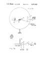
- FIG. 1is a block diagram representation of a preferred embodiment of the present invention.
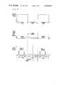
- FIG. 2is a block diagram representation of the sensor/display utilized in the present invention.
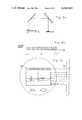
- FIG. 3ais a representation of a typical visual scene.
- FIG. 3bis a typical time history of one detector.
- FIG. 4is representative of the display of the typical visual scene.
- FIG. 5is an LED array video time history.
- FIG. 6ais a diagrammatic representation of the azimuth position pickoff scheme of the present invention.
- FIG. 6bis a graph of the output of the detector of the azimuth position pickoff mechanism of FIG. 6a.
- FIG. 6cis an illustrative view of the location of the azimuth position pickoff scheme relative to the display.
- FIG. 7ais another typical scene.
- FIG. 7bis an enlarged view of the scene of FIG. 7a.
- FIG. 7cis an enlarged view of a portion of FIG. 7b.
- FIG. 8ashows the gated output of video channel 16.
- FIG. 8bshows the gated output of video channel 16.
- FIG. 9ashows the gated output of video channel 16 in successive frames.
- FIG. 9bshows the effect of subtracting the second frame of video output from channel 16 as shown in FIG. 9a from the first frame of video output from channel 16 as shown in FIG. 9a.
- FIG. 9cis illustrative of how the data of FIG. 9b may be represented and stored in shift registers.
- FIG. 1shows the improved tracking system 10 of the present invention. It includes an infrared sensor and display shown generally at 12.
- the sensor/display 12is of the AN/TAS-4 variety modified to provide successive frames of electrical video signals as well as an optical image.
- One frame of datacorresponds to the scene when a beacon located on the missile is on and the next frame corresponds to the scene when the beacon is off.
- the sensor/display 12is shown in greater detail in FIG. 2. It is divided into eight distinct functional groups including afocal input optics 13, a mechanical scanner with driver 15, an LED array or display 17, an azimuth scan position pickoff circuit 19, eye piece optics 21, detector array 23 and video electronics including preamps 25 and postamps 27. Not shown in either FIG. 1 or FIG. 2 is a power supply or battery, nonetheless it is comtemplated that one of ordinary skill in the art would utilize some form of power supply in order to practice this invention.
- the spectral characteristics of the afocal optical coating at 13effectively limits the input optical energy to the desired region.
- the desired regionis 8 to 12 microns.
- the infrared sensor/display 12 of the present inventionprocesses thermally-radiated energy from terrestrial and man made objects as well as the energy radiated from the missile beacon which in the preferred embodiment also radiates in 8 to 12 micron region for improved aerosol and smoke penetration performance.
- the afocal optics 13receives infrared and visible energy.
- the input energyis mechanically scanned across the stationary detector array 23 such that the detectors are "painted" by the imaged energy.
- a typical scene imageis depicted in FIG. 3a.
- the sceneincludes a tree 64, a tank target 66, and the aft end of a missile looking at the laser beacon 62.
- the stationary detector arrayis represented at 23.
- the spike at 68would be representative of the missile beacon 62.
- the tank turret and the treewould be represented at 70 and 72 respectively. Note the ambient background level 74.
- Each detector outputis processed by a separate channel of preamplification and postamplification circuitry 25 and 27 located in the video electronics block.
- the channels of videopass into the video tracker 11 and are filtered. Assuming a missile has not been launched, the same input video information is transmitted without change in the LED array 17 of FIG. 2.
- the LED array 17has one LED corresponding to each detector element.
- the scan mirror 15serves doubly in acting as a scan mirror for input energy, as well as being the scan mirror for the visible LED output energy.
- the scan mirroris a plane parallel mirror having scan angles identical in magnitude for both input and LED energy.
- the image of the LED array 17,is shown in FIG. 4.
- the LED array 17effectively recreates the scene detected by the detector array 23.
- a time history of one channel of the LED array 17 videois shown in FIG. 5, together with the video used by the video tracker and the phase-locked beacon modulation. As illustrated, the display is electronically blanked during the beacon on frame. Note that the interlace scan results in two fields for each frame and that two frames are contained in one guidance period.
- the azimuth position pickoff 19generates precise azimuth location information relative to the line-of-sight crosshairs in the display for determining missile position in reference to the gunner's crosshairs.
- the azimuth position pickoff 19consists of a diode emitter with focusing optics 19a, and a detector 19b equipped with a picket fence type reticle.
- the emitter 19ais physically placed colinearly in close proximity to the LED array 17.
- the detector 19bis placed just behind the reticle assembly but above the operator's elevation field of view.
- the detector outputis a pulse train and covers an angular subtense equal to the field of view of the infrared sensor 12.
- the picket fence reticleis registered at the time of assembly with the vertical crosshair such that the pulse train is symetrically oriented with respect to the vertical crosshair. This establishes a precise azimuth reference in which the video tracker can determine the missile position error relative to the vertical crosshair.
- the video trackerreceives display video and azimuth position data from the infrared sensor 12, and missile identification logic (new or old) from the loaded round. (The new versus old distinction will be apparent from the following discussion.)
- the video trackerinhibits further processing and the firing proceeds in a conventional manner during which the gunner can steer through either the telescope or the LED array 17.
- the video trackerenables all processing circuitry and prepares to accept the infrared sensor display video.
- the frequency of the infrared sensor scan mirror 15is determined from the azimuth pickoff and a synchronization signal is sent by the timing circuit to the beacon 62. This initializes phase lock of the beacon modulation to exactly one-half the scan mirror frequency for the missile beacon blanking in the display 12 so that the gunner is not distracted by the beacon.
- Display videois examined by the tracker 11 for evidence of the beacon and the alternate frame display blanking is initiated.
- the missile beacon 62will appear as a very strong signal in the video relative to all other video information and as such as immediately recognized by the tracker electronics.
- Azimuth and elevation error signalsare generated, scaled, and made available for guidance of the missile in the manner described below.
- each channel of videodrives into a matched filter which could be implemented as a charged coupled device (CCD) transversal filter 14.
- the transversal filters 14eliminate some clutter by surpressing images larger than the beacon.
- the output of the transversal filtersprovides an input to a window multiplexing unit 16.
- the window multiplexing unit 16acts as a video gate to limit further processing to video in the vicinity of the missile beacon. This is illustrated in FIG. 7.
- FIG. 7ashows the tracker field of view.
- FIG. 7bis an enlargement of that portion of FIG. 7a near the center of the field of view. It reveals the video gate, the tank target and the missile beacon. (The missile beacon and the video gate do not appear in the display).
- FIG. 7cis a further enlargement of the video gate. It shows the target clutter as a shaded area.
- a horizontal pixel reference, and the interlace relationship of two detector elementswhich provide two fields of data for two channels of video output.
- the windowis equivalent to four detectors high by four
- FIGS. 8a and 8billustrate the gated outputs of channels 15 and 16 with reference the window of FIG. 7c.
- FIG. 8thus shows the electrical analog of the image contained within the video gate. It should be noted that these outputs are functions of time, but are discontinuous to show the relative change from frame-to-frame on a linear time-base scale. Starting with channel 16, field 1, and moving from right to left across the video gate pixel +2 shows an increase in amplitude, which is maintained in pixels +1, -1, and -2.
- the window multiplexing unit 16includes a position memory and adders and subtractors not shown which receive input from position detecting circuits 30 and 32 to set the video gate.
- Video signals within the variable size window or gateare passed from the multiplexer 16 to quantizer 20.
- Quantizer 20functions as an A to D converter and transforms analog video signals from the multiplexer 16 to digital signals for input to shift registers.
- Shift registers 22, 24, 26, and 28operate under control of a timing circuit 30 to store successive frames of video data. Individual frames of video are separated and loaded into different shift registers but remain coincident in pixel position. Serialized data enters shift registers until full. As data enters the subtractors, it is subtracted from data in the shift registers. The subtractors perform a repeated subtraction at the pixel rate to find the best minima or match.
- the "pixel” rateis the rate at which individual picture elements are loaded into the shift register.) While this best match is taking place, the pixel of the frame in which the beacon is present would be represented by a large digital number relative to the small numbers which represent residual clutter in the other pixels. Since the beacon is on for one complete frame and off for one, the main effect of subtracting frames is to accentuate the beacon and reduce the clutter to a small residue. A decoy beacon which is not in phase with the sensor 12 would be subtracted from itself, thus causing no problems. As mentioned above, the display 17 is blanked during beacon on flames to minimize operator distraction. FIG. 9 duplicates the channel 16 output and shows how frame-to-frame subtraction yields the uncontaminated beacon from video containing target control clutter plus beacon.
- the tracker 11compensates for clutter motion within the video gate by defining a two-dimensional zone within the video gate, hereinafter called the template domain, which contains the beacon plus a small amount of clutter. Also defined, is a larger two-dimensional zone, hereinafter called the search domain, which is comprised of the entire video gated information. Thus, the template domain is contained within the search domain.
- a best match from frame-to-framemay not be aligned in exact pixel coincidence.
- the best matchis therefore achieved by moving the template domain information within the search domain information until a best match is obtained. This movement of the template is accomplished by initiating the subtraction scheme as certain pixels of the second frame of data are being stored.
- the magnitude comparator 42performs a centroid comparison of the beacon data to determine where in time the peak of the beacon occurred. This point triggers a logic signal in the azimuth error detector 46 which is used to interrogate the azimuth position circuit 19 for azimuth location.
- the azimuth error detector 46generates a DC signal which corresponds to the azimuth position of the missile 54 relative to the gunners crosshairs. This is accomplished typically by utilizing a shift register (not shown) which counts the pulses from the azimuth scan position pickoff 19 and feeds the result into a digital-to-analog converter (also not shown). The result is a time-generated ramp voltage corresponding to the azimuth position of the scan mirror 15. Since the azimuth position pickoff 19 is set to be symmetrical about the crosshair reticle, a predetermined count relates to zero azimuth error, and hence zero volts out of the digital to analog converter. For example, if the beacon is detected by the left of the zero line of sight, the output is positive and similarly if the beacon is to the right the output is negative.
- the elevation positionis determined by assigning each of the detector channels an address which corresponds to the elevation angle in object space.
- channel 1may be below the zero line of sight and channel fifty above the zero line of sight.
- the tracker zerois permanently shifted downward to provide additional field of view above the zero line of sight.
- channel 15may correspond, for example, to zero elevation error.
- the beacon trackertells the elevation error detector 48 which channel or channels contain the beacon and a weighted value is assigned to that data. For example, channel 0 to 14 may be positive, with channels 16 to n being negative and channel 15 being zero.
- the outputs of the error detectors 46 and 48provide inputs to the missile guidance system computer 50 which then generates guidance command signals based upon the error signals to correct the missile line of flight. These commands are then transmitted to the missile via the handover weighting circuit 52 in a conventional manner.
- the shift registers 22, 24, 26, and 28, subtractors 32, 34, 36, and 38, comparator 42 and detectors 46 and 48provide means for taking the difference between successive frames of video data to ultimately provide signals indicative of the position of the missile 54.
- a beacon 62 mounted on the missile 54is effective at some portion of the missile flight to provide inputs to the scanner/display 12.
- the beacon 62is a laser, operational in the 8 to 12 micron range.
- the operation of the beaconis intermittent and under control of a beacon timing circuit 60 which has a synchronization determined by a synch circuit and a flight clock 58 and 56 respectively.
- the operation of the beaconis synchronized to the scanner 12 by timing circuit 30. It provides a beacon synch signal to the beacon timing circuit 60.
- the beaconneed not be intermittent and no frame-to-frame subtraction is needed. In this case missile guidance command can be issued every frame instead of every other frame, thus doubling the command rate.
- the timing circuit 30, the beacon 62 and the beacon azimuth error detector 46, elevation error detector 48, missile guidance system 50, handover weighting 52, flight clock 56, synch circuit 58, and beacon timing 60comprise means for providing radiant energy from the missile 54 to the sensor 12 during predetermined intervals of time.
- the gunneracquires a target using an optical sight, and when the target is within range, fires a missile.
- a beacon on the aft end of the missileis tracked by an infrared sensor.
- the input to the infrared sensoris converted by detectors into electrical pulses.
- the pulsesare applied to error detecting circuits, where the pulses are compared with a reference count.
- the output of each of the error detectorsis applied to its respective command signal generator and represents the error angle between the system line-of-sight to the missile and the line-of-sight to the target.
- a transversing unitgenerates voltage porportional to the rates of motion.
- the azimuth rate voltageis combined in a yaw command signal generator with the yaw error signal from a yaw error detector card.
- the elevation rate voltageis combined in a pitch command signal generator card with the pitch error signal from a pitch error detector card.
- the pitch command signal generator card outputis applied to the yaw command signal generator card.
- the output of the yaw command signal generator cardis a frequency multiplexed signal containing both pitch and yaw steering information and is supplied directly to the missile through the wire link.
- the improved tracking mode of the present inventionis identical to the mode previously described, however, in the mode of the present invention, the tracker 11 is tracking the synchronized beacon 62 and not the beacon associated with conventional line-of-sight missiles.
- the import of this differenceis that the synchronized beacon which operates in the 8 to 12 micron range is visible through darkness, smoke, haze and poor atmospheric visibility; whereas, the prior art beacon which normally operated in the shorter wavelength region is often severely attentuated under these conditions.
- the time between trigger and fireis used by the tracker 11 to synchronize the modulation of the laser beacon 62 to the scaning mirror 15.
- the tracker 11interrogates the missile to determine whether a conventional round is loaded or the dual mode round is loaded and selects the appropriate track line. That is, if an old round is loaded, the frame-to-frame subtraction technique of the present invention is by-passed and guidance signals are passed through the hand-over weighting circuit 52 on to the missile 54. Accordingly, if a dual mode round is loaded, the frame-to-fraime subtraction technique of the tracker 11 as described above is implemented.
- the tracker 11takes the video imagery from the sensor 12 and uses it to determine the location of the synchronized beacon 62 in the manner described above.
- the video tracker 11subsequently determines the missile beacon position with respect to the gunner's crosshair reticle and provides azimuth and elevation missile guidance commands to the missile 54. These commands are automatically substituted for the present missile tracker guidance commands at the predetermined time during the missile capture phase.
- Guidanceis then transferred to the FLIR tracker before the predicted worse case smoke attenuation.
Landscapes
- Engineering & Computer Science (AREA)
- Physics & Mathematics (AREA)
- Chemical & Material Sciences (AREA)
- Combustion & Propulsion (AREA)
- General Engineering & Computer Science (AREA)
- Electromagnetism (AREA)
- General Physics & Mathematics (AREA)
- Radar, Positioning & Navigation (AREA)
- Remote Sensing (AREA)
- Aiming, Guidance, Guns With A Light Source, Armor, Camouflage, And Targets (AREA)
- Closed-Circuit Television Systems (AREA)
Abstract
Description
Claims (2)
Priority Applications (1)
| Application Number | Priority Date | Filing Date | Title |
|---|---|---|---|
| US06/259,865US4424943A (en) | 1981-05-04 | 1981-05-04 | Tracking system |
Applications Claiming Priority (1)
| Application Number | Priority Date | Filing Date | Title |
|---|---|---|---|
| US06/259,865US4424943A (en) | 1981-05-04 | 1981-05-04 | Tracking system |
Publications (1)
| Publication Number | Publication Date |
|---|---|
| US4424943Atrue US4424943A (en) | 1984-01-10 |
Family
ID=22986748
Family Applications (1)
| Application Number | Title | Priority Date | Filing Date |
|---|---|---|---|
| US06/259,865Expired - LifetimeUS4424943A (en) | 1981-05-04 | 1981-05-04 | Tracking system |
Country Status (1)
| Country | Link |
|---|---|
| US (1) | US4424943A (en) |
Cited By (24)
| Publication number | Priority date | Publication date | Assignee | Title |
|---|---|---|---|---|
| FR2583523A1 (en)* | 1985-06-17 | 1986-12-19 | Aerospatiale | SYSTEM FOR LOCATING A MOBILE. |
| FR2636742A1 (en)* | 1988-09-22 | 1990-03-23 | Luquet Andre | Method and device making it possible to locate and track a moving object |
| EP0405678A1 (en)* | 1989-06-30 | 1991-01-02 | Societe Anonyme D'etudes Et Realisations Nucleaires - Sodern | Horizon sensor with improved precision |
| US5122990A (en)* | 1991-02-01 | 1992-06-16 | Rowe-Deines Instruments Incorporated | Bottom tracking system |
| EP0423984A3 (en)* | 1989-10-18 | 1992-07-08 | Hughes Aircraft Company | Synergistic tracker |
| US5138162A (en)* | 1988-12-16 | 1992-08-11 | The United States Of America As Represented By The Secretary Of The Army | Method and apparatus for producing enhanced images of curved thermal objects |
| US5142288A (en)* | 1987-12-11 | 1992-08-25 | Cleveland William C | Electro-optical IFF system |
| US5147088A (en)* | 1986-04-29 | 1992-09-15 | British Aerospace Public Limited Company | Missile tracking systems |
| US5345304A (en)* | 1992-12-17 | 1994-09-06 | Texas Instruments Incorporated | Integrated LADAR/FLIR sensor |
| US5651512A (en)* | 1995-09-28 | 1997-07-29 | Hughes Electronics | Missile tracking system with a thermal track link |
| US5793889A (en)* | 1995-05-25 | 1998-08-11 | Lockheed Corporation | Plume or combustion detection by time sequence differentiation |
| US5933241A (en)* | 1997-08-11 | 1999-08-03 | Lockheed Martin Corporation | Laser calibration of IR sensors using pulsed signals |
| US5990939A (en)* | 1995-09-28 | 1999-11-23 | Raytheon Company | Video demultiplexing interface for a missile tracking system |
| US6003810A (en)* | 1996-09-25 | 1999-12-21 | Aerospatiale Societe Nationale Industrielle | Homing head for a flying body |
| US6023058A (en)* | 1996-09-25 | 2000-02-08 | Aerospatiale Societe Nationale Industrielle | Photosensitive detector and mosaic of photosensitive detectors for the detection of luminous flashes and applications |
| US20060255204A1 (en)* | 2003-07-04 | 2006-11-16 | Mbda France | Rotating missile emitting light pulses |
| US7190304B1 (en)* | 2003-12-12 | 2007-03-13 | Bae Systems Information And Electronic Systems Integration Inc. | System for interception and defeat of rocket propelled grenades and method of use |
| US20080018264A1 (en)* | 2004-08-20 | 2008-01-24 | Mbda France | Method and Device for Producing an Optical Link Using Light Flashes |
| US20080018519A1 (en)* | 2005-12-06 | 2008-01-24 | Russell Berg | Anti-missile system and method |
| US20080262718A1 (en)* | 2007-04-17 | 2008-10-23 | Itt Manufacturing Enterprises, Inc. | Landmark Navigation for Vehicles Using Blinking Optical Beacons |
| US20080308670A1 (en)* | 2007-06-12 | 2008-12-18 | The Boeing Company | Systems and methods for optimizing the aimpoint for a missile |
| US20090080700A1 (en)* | 2005-05-25 | 2009-03-26 | Lau Daniel L | Projectile tracking system |
| US20100012765A1 (en)* | 2006-11-21 | 2010-01-21 | Mbda France | Aiming System With Integrated Deviation Meter |
| US20140376768A1 (en)* | 2013-06-19 | 2014-12-25 | The Boeing Company | Systems and Methods for Tracking Location of Movable Target Object |
Citations (16)
| Publication number | Priority date | Publication date | Assignee | Title |
|---|---|---|---|---|
| US2930894A (en) | 1954-07-13 | 1960-03-29 | Republic Aviat Corp | Optical sighting and tracking device |
| US3098933A (en) | 1957-10-23 | 1963-07-23 | Republic Aviat Corp | Photosensitive electronic tracking head |
| US3598344A (en) | 1964-06-01 | 1971-08-10 | Philco Ford Corp | Missile command system |
| US3711046A (en) | 1969-10-22 | 1973-01-16 | H Barhydt | Automatic missile guidance system |
| US3751166A (en) | 1971-06-03 | 1973-08-07 | Us Army | Command guidance transmitter system |
| US3761180A (en) | 1972-09-22 | 1973-09-25 | R Maxwell | Synchronously gated active night sight |
| US3820742A (en) | 1965-02-08 | 1974-06-28 | R Watkins | Missile guidance and control system |
| US3848830A (en) | 1971-11-20 | 1974-11-19 | Messerschmitt Boelkow Blohm | Missile guidance system |
| US3954228A (en) | 1965-11-16 | 1976-05-04 | The United States Of America As Represented By The Secretary Of The Army | Missile guidance system using an injection laser active missile seeker |
| US3998406A (en) | 1964-05-28 | 1976-12-21 | Aeronutronic Ford Corporation | Guided missile system |
| US4027837A (en) | 1969-10-23 | 1977-06-07 | The United States Of America As Represented By The Secretary Of The Army | Optical tracking link utilizing pulse burst modulation for solid state missile beacons |
| US4047117A (en) | 1974-01-17 | 1977-09-06 | Hughes Aircraft Company | Multi-level laser illuminator |
| US4047678A (en) | 1969-11-07 | 1977-09-13 | The United States Of America As Represented By The Secretary Of The Army | Modulated, dual frequency, optical tracking link for a command guidance missile system |
| US4162052A (en) | 1975-12-22 | 1979-07-24 | Societe Anonyme De Telecommunications | Night guidance of self-propelled missiles |
| US4174818A (en) | 1976-01-29 | 1979-11-20 | Elliott Brothers (London) Limited | Guidance systems for mobile craft |
| US4220296A (en) | 1976-11-03 | 1980-09-02 | Licentia Patent-Verwaltungs-G.M.B.H | Method for guiding the final phase of ballistic missiles |
- 1981
- 1981-05-04USUS06/259,865patent/US4424943A/ennot_activeExpired - Lifetime
Patent Citations (16)
| Publication number | Priority date | Publication date | Assignee | Title |
|---|---|---|---|---|
| US2930894A (en) | 1954-07-13 | 1960-03-29 | Republic Aviat Corp | Optical sighting and tracking device |
| US3098933A (en) | 1957-10-23 | 1963-07-23 | Republic Aviat Corp | Photosensitive electronic tracking head |
| US3998406A (en) | 1964-05-28 | 1976-12-21 | Aeronutronic Ford Corporation | Guided missile system |
| US3598344A (en) | 1964-06-01 | 1971-08-10 | Philco Ford Corp | Missile command system |
| US3820742A (en) | 1965-02-08 | 1974-06-28 | R Watkins | Missile guidance and control system |
| US3954228A (en) | 1965-11-16 | 1976-05-04 | The United States Of America As Represented By The Secretary Of The Army | Missile guidance system using an injection laser active missile seeker |
| US3711046A (en) | 1969-10-22 | 1973-01-16 | H Barhydt | Automatic missile guidance system |
| US4027837A (en) | 1969-10-23 | 1977-06-07 | The United States Of America As Represented By The Secretary Of The Army | Optical tracking link utilizing pulse burst modulation for solid state missile beacons |
| US4047678A (en) | 1969-11-07 | 1977-09-13 | The United States Of America As Represented By The Secretary Of The Army | Modulated, dual frequency, optical tracking link for a command guidance missile system |
| US3751166A (en) | 1971-06-03 | 1973-08-07 | Us Army | Command guidance transmitter system |
| US3848830A (en) | 1971-11-20 | 1974-11-19 | Messerschmitt Boelkow Blohm | Missile guidance system |
| US3761180A (en) | 1972-09-22 | 1973-09-25 | R Maxwell | Synchronously gated active night sight |
| US4047117A (en) | 1974-01-17 | 1977-09-06 | Hughes Aircraft Company | Multi-level laser illuminator |
| US4162052A (en) | 1975-12-22 | 1979-07-24 | Societe Anonyme De Telecommunications | Night guidance of self-propelled missiles |
| US4174818A (en) | 1976-01-29 | 1979-11-20 | Elliott Brothers (London) Limited | Guidance systems for mobile craft |
| US4220296A (en) | 1976-11-03 | 1980-09-02 | Licentia Patent-Verwaltungs-G.M.B.H | Method for guiding the final phase of ballistic missiles |
Cited By (41)
| Publication number | Priority date | Publication date | Assignee | Title |
|---|---|---|---|---|
| JPS61291899A (en)* | 1985-06-17 | 1986-12-22 | アエロスパテイアル・ソシエテ・ナシヨナル・アンダストリエル | System for positioning moving body |
| EP0206912A1 (en)* | 1985-06-17 | 1986-12-30 | AEROSPATIALE Société Nationale Industrielle | Position finding system for a moving object |
| US4710028A (en)* | 1985-06-17 | 1987-12-01 | Aerospatiale Societe Nationale Industrielle | System for locating a body in motion |
| FR2583523A1 (en)* | 1985-06-17 | 1986-12-19 | Aerospatiale | SYSTEM FOR LOCATING A MOBILE. |
| JPH0789037B2 (en) | 1985-06-17 | 1995-09-27 | アエロスパテイアル・ソシエテ・ナシヨナル・アンダストリエル | Positioning device for moving objects |
| FR2683635A1 (en)* | 1986-04-29 | 1993-05-14 | British Aerospace | MISSILE TRACKING SYSTEMS. |
| US5147088A (en)* | 1986-04-29 | 1992-09-15 | British Aerospace Public Limited Company | Missile tracking systems |
| US5142288A (en)* | 1987-12-11 | 1992-08-25 | Cleveland William C | Electro-optical IFF system |
| FR2636742A1 (en)* | 1988-09-22 | 1990-03-23 | Luquet Andre | Method and device making it possible to locate and track a moving object |
| US5138162A (en)* | 1988-12-16 | 1992-08-11 | The United States Of America As Represented By The Secretary Of The Army | Method and apparatus for producing enhanced images of curved thermal objects |
| FR2649196A1 (en)* | 1989-06-30 | 1991-01-04 | Sodern | TERRESTRIAL HORIZON SENSOR WITH IMPROVED PRECISION |
| EP0405678A1 (en)* | 1989-06-30 | 1991-01-02 | Societe Anonyme D'etudes Et Realisations Nucleaires - Sodern | Horizon sensor with improved precision |
| EP0423984A3 (en)* | 1989-10-18 | 1992-07-08 | Hughes Aircraft Company | Synergistic tracker |
| TR25046A (en)* | 1989-10-18 | 1992-09-01 | Hughes Aircraft Co | SINERJISTIKN SUPER-CONDUCTIVE MOD / LOW-MOVEMENT-RATED COOLER WITHOUT SUPER-CONDUCTIVE MOD. |
| US5122990A (en)* | 1991-02-01 | 1992-06-16 | Rowe-Deines Instruments Incorporated | Bottom tracking system |
| US5345304A (en)* | 1992-12-17 | 1994-09-06 | Texas Instruments Incorporated | Integrated LADAR/FLIR sensor |
| US5793889A (en)* | 1995-05-25 | 1998-08-11 | Lockheed Corporation | Plume or combustion detection by time sequence differentiation |
| US5651512A (en)* | 1995-09-28 | 1997-07-29 | Hughes Electronics | Missile tracking system with a thermal track link |
| US5990939A (en)* | 1995-09-28 | 1999-11-23 | Raytheon Company | Video demultiplexing interface for a missile tracking system |
| US6003810A (en)* | 1996-09-25 | 1999-12-21 | Aerospatiale Societe Nationale Industrielle | Homing head for a flying body |
| US6023058A (en)* | 1996-09-25 | 2000-02-08 | Aerospatiale Societe Nationale Industrielle | Photosensitive detector and mosaic of photosensitive detectors for the detection of luminous flashes and applications |
| US5933241A (en)* | 1997-08-11 | 1999-08-03 | Lockheed Martin Corporation | Laser calibration of IR sensors using pulsed signals |
| US20060255204A1 (en)* | 2003-07-04 | 2006-11-16 | Mbda France | Rotating missile emitting light pulses |
| US7410119B2 (en)* | 2003-07-04 | 2008-08-12 | Mbda France | Rotating missile emitting light pulses |
| US7190304B1 (en)* | 2003-12-12 | 2007-03-13 | Bae Systems Information And Electronic Systems Integration Inc. | System for interception and defeat of rocket propelled grenades and method of use |
| US20080018264A1 (en)* | 2004-08-20 | 2008-01-24 | Mbda France | Method and Device for Producing an Optical Link Using Light Flashes |
| US7582853B2 (en)* | 2004-08-20 | 2009-09-01 | Mbda France | Method and device for producing an optical link using light flashes |
| US20090080700A1 (en)* | 2005-05-25 | 2009-03-26 | Lau Daniel L | Projectile tracking system |
| US7504982B2 (en)* | 2005-12-06 | 2009-03-17 | Raytheon Company | Anti-Missile system and method |
| US20080018519A1 (en)* | 2005-12-06 | 2008-01-24 | Russell Berg | Anti-missile system and method |
| WO2008108860A3 (en)* | 2006-06-12 | 2008-12-04 | Raytheon Co | Anti-missile system and method |
| US20100012765A1 (en)* | 2006-11-21 | 2010-01-21 | Mbda France | Aiming System With Integrated Deviation Meter |
| US8022343B2 (en)* | 2006-11-21 | 2011-09-20 | Mbda France | Aiming system with integrated deviation meter |
| US20080262718A1 (en)* | 2007-04-17 | 2008-10-23 | Itt Manufacturing Enterprises, Inc. | Landmark Navigation for Vehicles Using Blinking Optical Beacons |
| US7739034B2 (en)* | 2007-04-17 | 2010-06-15 | Itt Manufacturing Enterprises, Inc. | Landmark navigation for vehicles using blinking optical beacons |
| US20080308670A1 (en)* | 2007-06-12 | 2008-12-18 | The Boeing Company | Systems and methods for optimizing the aimpoint for a missile |
| US7968831B2 (en)* | 2007-06-12 | 2011-06-28 | The Boeing Company | Systems and methods for optimizing the aimpoint for a missile |
| US20140376768A1 (en)* | 2013-06-19 | 2014-12-25 | The Boeing Company | Systems and Methods for Tracking Location of Movable Target Object |
| US9043146B2 (en)* | 2013-06-19 | 2015-05-26 | The Boeing Company | Systems and methods for tracking location of movable target object |
| US20150207987A1 (en)* | 2013-06-19 | 2015-07-23 | The Boeing Company | Systems and Methods for Tracking Location of Movable Target Object |
| US9197810B2 (en)* | 2013-06-19 | 2015-11-24 | The Boeing Company | Systems and methods for tracking location of movable target object |
Similar Documents
| Publication | Publication Date | Title |
|---|---|---|
| US4424943A (en) | Tracking system | |
| US3974328A (en) | Line scan area signature detection system | |
| US5379676A (en) | Fire control system | |
| US4274609A (en) | Target and missile angle tracking method and system for guiding missiles on to targets | |
| US4611771A (en) | Fiber optic track/reaim system | |
| US5483865A (en) | Aircraft sighting system | |
| US4155096A (en) | Automatic laser boresighting | |
| US3567163A (en) | Guidance system | |
| US5077609A (en) | Optoelectronic system of assistance in attack and navigation missions | |
| US5134409A (en) | Surveillance sensor which is provided with at least one surveillance radar antenna rotatable about at least one first axis of rotation | |
| US3897150A (en) | Scanned laser imaging and ranging system | |
| US8358404B2 (en) | Laser ranging, tracking and designation using 3-D focal planes | |
| US5062586A (en) | Missile tracking, guidance and control apparatus | |
| US4316218A (en) | Video tracker | |
| US3876308A (en) | Automatic command guidance system using optical trackers | |
| US8022343B2 (en) | Aiming system with integrated deviation meter | |
| US5964432A (en) | System for searching for, detecting and tracking flying targets | |
| EP0911646A2 (en) | Imaging self-referencing tracker and associated methodology | |
| US4742390A (en) | Elevatable observation and target system for combat vehicles | |
| US4103847A (en) | Line scan area signature detection method | |
| US3290506A (en) | Photoelectric object tracking system using signal delay and multiplying correlators | |
| US5274236A (en) | Method and apparatus for registering two images from different sensors | |
| Downey et al. | Electro-optical tracking systems considerations | |
| US6260792B1 (en) | Tracking and guidance system with modulated missile-mounted laser beacon | |
| EP0064168A1 (en) | Jitter compensated scene stabilized missile guidance system |
Legal Events
| Date | Code | Title | Description |
|---|---|---|---|
| AS | Assignment | Owner name:HUGHES AIRCRAFT COMPANY, CULVER CITY, CA., A CORP Free format text:ASSIGNMENT OF ASSIGNORS INTEREST.;ASSIGNORS:ZWIRN ROBERT;BOZEMAN JOHN W.;REEL/FRAME:003881/0861 Effective date:19810429 Owner name:HUGHES AIRCRAFT COMPANY, A CORP. OF DE., CALIFORNI Free format text:ASSIGNMENT OF ASSIGNORS INTEREST;ASSIGNORS:ZWIRN ROBERT;BOZEMAN JOHN W.;REEL/FRAME:003881/0861 Effective date:19810429 | |
| STCF | Information on status: patent grant | Free format text:PATENTED CASE | |
| MAFP | Maintenance fee payment | Free format text:PAYMENT OF MAINTENANCE FEE, 4TH YEAR, PL 96-517 (ORIGINAL EVENT CODE: M170); ENTITY STATUS OF PATENT OWNER: LARGE ENTITY Year of fee payment:4 | |
| FEPP | Fee payment procedure | Free format text:MAINTENANCE FEE REMINDER MAILED (ORIGINAL EVENT CODE: REM.); ENTITY STATUS OF PATENT OWNER: LARGE ENTITY | |
| FEPP | Fee payment procedure | Free format text:SURCHARGE FOR LATE PAYMENT, LARGE ENTITY (ORIGINAL EVENT CODE: M186); ENTITY STATUS OF PATENT OWNER: LARGE ENTITY | |
| MAFP | Maintenance fee payment | Free format text:PAYMENT OF MAINTENANCE FEE, 8TH YEAR, LARGE ENTITY (ORIGINAL EVENT CODE: M184); ENTITY STATUS OF PATENT OWNER: LARGE ENTITY Year of fee payment:8 | |
| FP | Lapsed due to failure to pay maintenance fee | Effective date:19920112 | |
| MAFP | Maintenance fee payment | Free format text:PAYMENT OF MAINTENANCE FEE, 12TH YEAR, LARGE ENTITY (ORIGINAL EVENT CODE: M185); ENTITY STATUS OF PATENT OWNER: LARGE ENTITY Year of fee payment:12 | |
| FEPP | Fee payment procedure | Free format text:PAYOR NUMBER ASSIGNED (ORIGINAL EVENT CODE: ASPN); ENTITY STATUS OF PATENT OWNER: LARGE ENTITY |