US4424720A - Mechanism for screw drive and syringe plunger engagement/disengagement - Google Patents
Mechanism for screw drive and syringe plunger engagement/disengagementDownload PDFInfo
- Publication number
- US4424720A US4424720AUS06/216,768US21676880AUS4424720AUS 4424720 AUS4424720 AUS 4424720AUS 21676880 AUS21676880 AUS 21676880AUS 4424720 AUS4424720 AUS 4424720A
- Authority
- US
- United States
- Prior art keywords
- lead screw
- traveler
- plunger
- combination
- engagement
- Prior art date
- Legal status (The legal status is an assumption and is not a legal conclusion. Google has not performed a legal analysis and makes no representation as to the accuracy of the status listed.)
- Expired - Lifetime
Links
- 230000007246mechanismEffects0.000titleabstractdescription50
- 230000009471actionEffects0.000claimsdescription14
- 230000008878couplingEffects0.000claimsdescription9
- 238000010168coupling processMethods0.000claimsdescription9
- 238000005859coupling reactionMethods0.000claimsdescription9
- 238000001802infusionMethods0.000abstractdescription8
- 238000012544monitoring processMethods0.000abstractdescription3
- 239000012530fluidSubstances0.000description23
- 238000009434installationMethods0.000description11
- 238000000034methodMethods0.000description6
- 230000000712assemblyEffects0.000description5
- 238000000429assemblyMethods0.000description5
- 230000006835compressionEffects0.000description5
- 238000007906compressionMethods0.000description5
- 238000001990intravenous administrationMethods0.000description4
- 230000000694effectsEffects0.000description3
- 230000006870functionEffects0.000description3
- 230000003287optical effectEffects0.000description3
- 230000008569processEffects0.000description3
- 238000007790scrapingMethods0.000description3
- 230000001276controlling effectEffects0.000description2
- 230000005484gravityEffects0.000description2
- 239000007788liquidSubstances0.000description2
- 230000002028prematureEffects0.000description2
- 230000001133accelerationEffects0.000description1
- 238000013459approachMethods0.000description1
- 230000004872arterial blood pressureEffects0.000description1
- 230000008901benefitEffects0.000description1
- 239000008280bloodSubstances0.000description1
- 210000004369bloodAnatomy0.000description1
- 230000000747cardiac effectEffects0.000description1
- 230000002301combined effectEffects0.000description1
- 230000001351cycling effectEffects0.000description1
- 238000013461designMethods0.000description1
- 238000011161developmentMethods0.000description1
- 239000003814drugSubstances0.000description1
- 229940079593drugDrugs0.000description1
- 230000009977dual effectEffects0.000description1
- 238000002637fluid replacement therapyMethods0.000description1
- 230000002706hydrostatic effectEffects0.000description1
- 230000006872improvementEffects0.000description1
- 230000003993interactionEffects0.000description1
- 238000012986modificationMethods0.000description1
- 230000004048modificationEffects0.000description1
- 235000015097nutrientsNutrition0.000description1
- 238000007911parenteral administrationMethods0.000description1
- 230000002035prolonged effectEffects0.000description1
- 230000001105regulatory effectEffects0.000description1
- 230000004044responseEffects0.000description1
- 238000000926separation methodMethods0.000description1
- 239000007787solidSubstances0.000description1
Images


Classifications
- A—HUMAN NECESSITIES
- A61—MEDICAL OR VETERINARY SCIENCE; HYGIENE
- A61M—DEVICES FOR INTRODUCING MEDIA INTO, OR ONTO, THE BODY; DEVICES FOR TRANSDUCING BODY MEDIA OR FOR TAKING MEDIA FROM THE BODY; DEVICES FOR PRODUCING OR ENDING SLEEP OR STUPOR
- A61M5/00—Devices for bringing media into the body in a subcutaneous, intra-vascular or intramuscular way; Accessories therefor, e.g. filling or cleaning devices, arm-rests
- A61M5/14—Infusion devices, e.g. infusing by gravity; Blood infusion; Accessories therefor
- A61M5/142—Pressure infusion, e.g. using pumps
- A61M5/145—Pressure infusion, e.g. using pumps using pressurised reservoirs, e.g. pressurised by means of pistons
- A61M5/1452—Pressure infusion, e.g. using pumps using pressurised reservoirs, e.g. pressurised by means of pistons pressurised by means of pistons
- A61M5/1456—Pressure infusion, e.g. using pumps using pressurised reservoirs, e.g. pressurised by means of pistons pressurised by means of pistons with a replaceable reservoir comprising a piston rod to be moved into the reservoir, e.g. the piston rod is part of the removable reservoir
- B—PERFORMING OPERATIONS; TRANSPORTING
- B23—MACHINE TOOLS; METAL-WORKING NOT OTHERWISE PROVIDED FOR
- B23Q—DETAILS, COMPONENTS, OR ACCESSORIES FOR MACHINE TOOLS, e.g. ARRANGEMENTS FOR COPYING OR CONTROLLING; MACHINE TOOLS IN GENERAL CHARACTERISED BY THE CONSTRUCTION OF PARTICULAR DETAILS OR COMPONENTS; COMBINATIONS OR ASSOCIATIONS OF METAL-WORKING MACHINES, NOT DIRECTED TO A PARTICULAR RESULT
- B23Q5/00—Driving or feeding mechanisms; Control arrangements therefor
- B23Q5/22—Feeding members carrying tools or work
- B23Q5/34—Feeding other members supporting tools or work, e.g. saddles, tool-slides, through mechanical transmission
- B23Q5/38—Feeding other members supporting tools or work, e.g. saddles, tool-slides, through mechanical transmission feeding continuously
- B23Q5/40—Feeding other members supporting tools or work, e.g. saddles, tool-slides, through mechanical transmission feeding continuously by feed shaft, e.g. lead screw
- B23Q5/406—Feeding other members supporting tools or work, e.g. saddles, tool-slides, through mechanical transmission feeding continuously by feed shaft, e.g. lead screw with means for meshing screw and nut
- A—HUMAN NECESSITIES
- A61—MEDICAL OR VETERINARY SCIENCE; HYGIENE
- A61M—DEVICES FOR INTRODUCING MEDIA INTO, OR ONTO, THE BODY; DEVICES FOR TRANSDUCING BODY MEDIA OR FOR TAKING MEDIA FROM THE BODY; DEVICES FOR PRODUCING OR ENDING SLEEP OR STUPOR
- A61M5/00—Devices for bringing media into the body in a subcutaneous, intra-vascular or intramuscular way; Accessories therefor, e.g. filling or cleaning devices, arm-rests
- A61M5/14—Infusion devices, e.g. infusing by gravity; Blood infusion; Accessories therefor
- A61M5/142—Pressure infusion, e.g. using pumps
- A61M5/145—Pressure infusion, e.g. using pumps using pressurised reservoirs, e.g. pressurised by means of pistons
- A61M5/1452—Pressure infusion, e.g. using pumps using pressurised reservoirs, e.g. pressurised by means of pistons pressurised by means of pistons
- A61M2005/14573—Pressure infusion, e.g. using pumps using pressurised reservoirs, e.g. pressurised by means of pistons pressurised by means of pistons with a replaceable reservoir for quick connection/disconnection with a driving system
- A—HUMAN NECESSITIES
- A61—MEDICAL OR VETERINARY SCIENCE; HYGIENE
- A61M—DEVICES FOR INTRODUCING MEDIA INTO, OR ONTO, THE BODY; DEVICES FOR TRANSDUCING BODY MEDIA OR FOR TAKING MEDIA FROM THE BODY; DEVICES FOR PRODUCING OR ENDING SLEEP OR STUPOR
- A61M5/00—Devices for bringing media into the body in a subcutaneous, intra-vascular or intramuscular way; Accessories therefor, e.g. filling or cleaning devices, arm-rests
- A61M5/14—Infusion devices, e.g. infusing by gravity; Blood infusion; Accessories therefor
- A61M5/142—Pressure infusion, e.g. using pumps
- A61M5/145—Pressure infusion, e.g. using pumps using pressurised reservoirs, e.g. pressurised by means of pistons
- A61M5/1452—Pressure infusion, e.g. using pumps using pressurised reservoirs, e.g. pressurised by means of pistons pressurised by means of pistons
- A61M5/1458—Means for capture of the plunger flange
- Y—GENERAL TAGGING OF NEW TECHNOLOGICAL DEVELOPMENTS; GENERAL TAGGING OF CROSS-SECTIONAL TECHNOLOGIES SPANNING OVER SEVERAL SECTIONS OF THE IPC; TECHNICAL SUBJECTS COVERED BY FORMER USPC CROSS-REFERENCE ART COLLECTIONS [XRACs] AND DIGESTS
- Y10—TECHNICAL SUBJECTS COVERED BY FORMER USPC
- Y10S—TECHNICAL SUBJECTS COVERED BY FORMER USPC CROSS-REFERENCE ART COLLECTIONS [XRACs] AND DIGESTS
- Y10S128/00—Surgery
- Y10S128/01—Motorized syringe
- Y—GENERAL TAGGING OF NEW TECHNOLOGICAL DEVELOPMENTS; GENERAL TAGGING OF CROSS-SECTIONAL TECHNOLOGIES SPANNING OVER SEVERAL SECTIONS OF THE IPC; TECHNICAL SUBJECTS COVERED BY FORMER USPC CROSS-REFERENCE ART COLLECTIONS [XRACs] AND DIGESTS
- Y10—TECHNICAL SUBJECTS COVERED BY FORMER USPC
- Y10T—TECHNICAL SUBJECTS COVERED BY FORMER US CLASSIFICATION
- Y10T74/00—Machine element or mechanism
- Y10T74/18—Mechanical movements
- Y10T74/18856—Oscillating to oscillating
- Y10T74/18864—Snap action
- Y—GENERAL TAGGING OF NEW TECHNOLOGICAL DEVELOPMENTS; GENERAL TAGGING OF CROSS-SECTIONAL TECHNOLOGIES SPANNING OVER SEVERAL SECTIONS OF THE IPC; TECHNICAL SUBJECTS COVERED BY FORMER USPC CROSS-REFERENCE ART COLLECTIONS [XRACs] AND DIGESTS
- Y10—TECHNICAL SUBJECTS COVERED BY FORMER USPC
- Y10T—TECHNICAL SUBJECTS COVERED BY FORMER US CLASSIFICATION
- Y10T74/00—Machine element or mechanism
- Y10T74/19—Gearing
- Y10T74/19642—Directly cooperating gears
- Y10T74/19698—Spiral
- Y10T74/19702—Screw and nut
- Y10T74/19735—Nut disengageable from screw
Definitions
- This inventionrelates generally to improvements in mechanisms for screw drive engagement and disengagement, and more particularly, to a new and improved mechanical system for use in a syringe pump of the type requiring engagement and disengagement of a lead screw to facilitate installation of a syringe for parenteral administration (referred to herein as "intravenous administration” or "IV administration”) of medical fluids.
- an intravenous solution administration settypically is a disposable plastic product, and comprises a drop chamber adapted to be connected to a fluid source, a length of tubing extending from the chamber to the patient and a valve mechanism, such as a roller clamp on the tubing.
- the drip chamber of the IV administration setserves a dual function of allowing a nurse or other attendant to observe the rate at which the fluid drips out of the fluid source and also creates a reservoir for the fluid at the lower end of the drip chamber to insure that no air enters the main feeding tube leading to the patient.
- the IV administration of medical fluids by gravity induced hydrostatic pressure infusion of the liquid from a fluid source suspended above a patientmay be susceptible to fluid flow rate variations due to changes in the fluid level in the bottle, changes in temperature, changes in the venous or arterial pressure of the patient, patient movement, and drift in the effective setting of the roller clamp or other valve mechanism pinching the feeding tube.
- fluid flow rate variationsdue to changes in the fluid level in the bottle, changes in temperature, changes in the venous or arterial pressure of the patient, patient movement, and drift in the effective setting of the roller clamp or other valve mechanism pinching the feeding tube.
- there are a number of situationssuch as in intensive care, cardiac and pediatric patients, or where rather critical drugs are being administered, where the desired drop flow rate must be capable of rather precise selection and must not drift beyond certain prescribed limits in spite of varying load conditions.
- syringe pumpshave been developed and have become popular in the IV administration of fluids into the human body, such syringe pumps typically embodying a motor driving a plunger within a syringe body to expel fluid from the syringe at a controlled rate through a length of tubing and into the patient.
- syringe pumphas a syringe plunger mover that is coupled for engagement with a rotary-driven lead screw for linear travel along the lead screw.
- These pumpsare especially adapted to receive a self-contained syringe, installed to have the syringe plunger mover drive the syringe plunger. Because such syringes are typically pre-loaded with varying amounts of fluid and the syringe plunger mover may be in any position along its linear travel from a previous use, some mechanism is necessarily provided for selectively disengaging the syringe plunger mover from the lead screw to enable manual repositioning of it into alignment with the free end of the syringe plunger upon installation.
- the present inventionresides in a new and improved mechanism for lead screw engagement and disengagement, in which a traveler mechanism, by means of selective actuation, is moved into and out of threaded engagement with the lead screw in a manner virtually eliminating the possibility of partial thread engagement that could result in thread scraping, minimizing thread collision forces and ensuring proper thread alignment before forcing the traveler mechanism into lead screw engagement.
- the inventionadditionally resides in a syringe plunger mover mounted for rotation between positions of engagement and disengagement with the free end of a syringe plunger.
- the mover arm in the disengaged positionallows for unobstructed syringe installation regardless of the linear position of the mover with respect to the plunger, and also is capable of sliding movement into proper alignment from either side of the free end of the installed plunger.
- the moverserves as part of a rotary crank means for actuating the traveler mechanism whereby rotation of the mover to its disengaged position with the syringe plunger causes traveler mechanism disengagement with the lead screw, and conversely, rotation of the mover into engagement with the plunger causes traveler mechanism engagement with the lead screw.
- the traveler mechanismincludes a biasing system for releasably biasing it in either the state of engagement or the state of disengagement with the lead screw, the biasing system preferably producing an over-center action as the traveler mechanism moves between those two states.
- the traveler mechanismdoes not move into or out of engagement with the lead screw until after its biasing system has travelled over center, and because of the manner in which the traveler mechanism is coupled to its actuator, the traveler mechanism then completes its movement independent of the actuator.
- the traveler mechanismcompletes engagement or disengagement, as the case may be, due only to its own internal biasing system, with means provided to limit collision forces with the lead screw upon engagement and to cause rapid disengagement once the biasing system is over center.
- the present inventionprovides a new and improved mechanism in which a split nut-pair are mounted for movement into and out of engagement with the lead screw, each split nut having a projecting pin received in a cam groove formed in a rotary cam disk so that rotation of the cam disk controls movement of the split nuts.
- the split-nut pairis moved and locked into lead screw engagement by rotation of the cam disk in one direction to the fullest possible extent, while movement of the cam disk to the fullest extent possible in the opposite direction moves and locks the split-nut pair out of engagement, mechanical limits or stops being provided to limit rotational travel of the cam disk.
- Biasing meansin the form of a compression spring assembly is connected to the cam disk for over-center action, and an actuator mechanism is provided for bringing the spring-to-cam disk assembly from one or the other of its extreme rotational positions over center towards the opposite extreme position, at which point the spring assembly provides automatic rotational control of cam disk movement to the opposite extreme.
- the actuator mechanismin not fixedly coupled to the cam disk, but rather is loosely keyed so that after bringing the cam disk over center, the cam disk releases from the actuator mechanism and continues to move to the opposite extreme position due solely to the biasing effect of its own spring system.
- Mechanical limits or stops for the actuator mechanismare provided to help protect the split-nut pair and lead screw against damage due to overly vigorous operation of the actuator mechanism by the user, particularly during engagement.
- the cam disk grooveseach include a pair of arcuate locking portions for retaining the split-nut pins in the fully disengaged position or the fully engaged position, depending on the rotational state of the cam disk, and further include separate segments between these two locking portions for prescribed control of the split-nut pair during engagement and rapid separation of the split-nut pair during disengagement.
- Each of these latter segmentsis configured within the cam grooves so that very little, if any, split-nut pair movement occurs until after the spring-to-cam disk assembly passes over center during rotation.
- the cam groove segment controlling split-nut pair engagementis configured to limit the collision force between the threads of the split-nut pair and the threads of the lead screw.
- the actuator mechanismcomprises a crank arm having a one end connected to a crank shaft, which in turn connects to a crank disk for keying to the cam disk.
- the crank armis rotatable between closed and opened positions whereby its free end either grasps or releases, respectively, the free end (or "thumb-rest") of a syringe plunger.
- Another compression spring assemblyis connected to the crank disk for over center action tending to lock the crank arm in one or the other of its extreme rotational states.
- crank armcorresponds to disengagement of the split-nut pair from the lead screw
- crank arm closed positioncorresponds to split-nut pair engagement with the lead screw.
- the respective spring assemblies for the crank disk and the cam diskautomatically lock them in the open-and-disengaged states during manual positioning of the crank arm into alignment with the thumbrest of the syringe plunger.
- crank armprovides clearance for installation of a syringe regardless of the linear position of the crank arm at the time.
- the crank armmay initially be linearly positioned forwardly of the thumbrest, it being possible with the present invention to then slide the crank arm rearwardly past the thumbrest and then forwardly into alignment for crank arm closure.
- the crank armhas a beveled edge that lifts the thumbrest out of the way to permit the crank arm to pass by from the forward (i.e., syringe plunger) side of the thumbrest.
- the margin of the crank arm pushing surfacecatches the lip of the thumbrest as a manual indication of alignment, from which crank arm rotation to the closed position follows.
- a fixed light source and photoelectric sensor arrangementprovides a reference light beam which is interrupted by an opaque flag in all rotational positions of the crank arm, except when the crank arm is closed and properly grasping the thumbrest, so that a signal can be developed to enable proper pump function.
- the new and improved lead screw and syringe plunger engagement/disengagement mechanism of the present inventionis extremely simple and reliable.
- the mechanismprovides proper balanced-force engagement of the lead screw, and locked disengagement of the split-nut pair to eliminate the need for continuous actuation of a button or lever by the user in order to manually position the crank arm for alignment with the plunger thumbrest.
- the mechanismalso provides for convenient installation of a syringe that does not require pre-alignment of the crank arm.
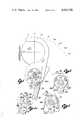
- FIG. 1is a perspective view, partially broken away, illustrating a syringe infusion pump utilizing a mechanical engagement and disengagement system embodying the principles of the present invention
- FIG. 2is an exploded perspective view of the structural components of the mechanical engagement and disengagement system, while FIG. 2a is a fragmentary side elevational view of the optical mechanism for monitoring proper engagement of the crank arm with the thumbrest at the free end of the syringe plunger;
- FIG. 3is a fragmentary elevational view of the crank disk and rear housing taken from the side opposite that shown in FIG. 2;
- FIG. 4is a elevational view of the cam disk taken from the side opposite that shown in FIG. 2, and showing a fragmented outline of the front housing around the cam disk, while FIG. 4a is a enlarged, fragmentary view of one of the cam grooves formed in the cam disk;
- FIG. 5is a view, primarily schematic in nature, taken along the axis of the lead screw from the left of the split-nut pair as shown in FIG. 2, and illustrates the interrelationship between the primary components of the mechanical engagement and disengagement system of the invention;
- FIG. 6a-6his a series of fragmentary views, also primarily schematic in nature, in which the the split-nut pair and pins, the cam grooves and the key of the cam disk, and the keyway of the crank disk are superimposed and shown in a variety of positions relative to one another;
- FIG. 7is a fragmentary sectional view taken along the line 7--7 in FIG. 1, and partially broken away to show the manner in which the crank arm grasps the thumbrest of the syringe plunger, the fully opened position of the crank arm being shown in phantom;
- FIG. 8is a fragmentary top plan view, primarily schematic in nature and partially in section, illustrating linear travel of the crank arm, in the fully opened position, into alignment with the thumbrest;
- FIG. 9is a view similar to FIG. 8, showing the crank arm rotated to the fully closed position, grasping the thumbrest.
- FIG. 1there is shown a syringe infusion pump, indicated generally by reference numeral 10, in which the mechanical system is embodied.
- a syringe infusion pumpindicated generally by reference numeral 10
- the mechanical systemis embodied.
- the infusion pump 10 shown in FIG. 1has a syringe 11, comprising a body 11a and a plunger 11b, installed in it to be acted upon by the mechanical system embodied in the pump for the controlled delivery of fluid from the syringe through an IV tube (not shown) to the patient.
- the syringe 11is of the self-contained variety (i.e., when installed it is pre-loaded with the precise volume of fluid to be infused to the patient) and the fluid is delivered by means of a single, prolonged pump stroke applied by the pump 10 to the syringe plunger 11b.
- the syringe 11does not draw fluid from another source, as by cycling the syringe through alternate fill and pump strokes.
- the syringe pump 10is contained in a generally oblong housing 12 including, along one side of the housing, a compartment 12a, in which various elements of the mechanical system of the present invention are disposed, and a base surface 12b adjacent to and generally lower than the compartment.
- a compartment 12aformed on an upper surface 12c of the compartment 12a are a pair of longitudinally spaced-apart, upstanding cradle members 13a, 13b into which the cylindrical body 11a of the syringe 11 is installed, with the syringe plunger 11b extending out over the base surface 12b.
- a control panel 14including various operating controls and indicators, which need not be described further herein for an understanding of the invention.
- a traveler rod 15extends almost the length of the syringe pump, through an end wall 12d of the compartment 12a at its intersection with the base surface 12b, so that a portion of the traveler rod is disposed within the compartment and the remaining portion of the traveler rod extends above and across the base surface.
- the traveler rod portion within the compartment 12adefines a lead screw 15a, while the portion outside the housing presents a smooth cylindrical surface.
- One end of the traveler rod 15is supported by, and journalled for rotation in, an upstanding end bracket 16 protruding from the base surface 12b, and the other end is coupled to a geared motor (not shown), mounted within the compartment 12a for selective rotation of the traveler rod under the control of any appropriate electrical control system.
- a geared motor(not shown), mounted within the compartment 12a for selective rotation of the traveler rod under the control of any appropriate electrical control system.
- One suitable control systemis shown and described in an application for U.S. Pat., Ser. No. 216,762, filed concurrently here
- the thumbrest 11c at the free end of the syringe plunger 11bis grasped by one end of a syringe plunger mover, which will be referred to herein as the crank arm 17.
- the thumbrest 11cis obscured in FIG. 1 by the crank arm 17, but is clearly shown in FIGS. 7-9.
- the crank arm 17has its other end fixedly attached to a hollow crank shaft 18, which is received over the traveler rod 15.
- the relationship between the crank shaft 18 and the traveler rod 15is such that not only are they rotatable relative to one another, but the crank shaft is also capable of linear travel along the traveler rod.
- crank shaft 18extends through the compartment end wall 12d and into the compartment 12a where the crank shaft is coupled to a traveler mechanism, indicated generally by reference numeral 19, received around the lead screw 15a.
- the traveler mechanism 19can be seen in FIG. 1 through the portion of the compartment 12a that has been broken away for clarity.
- the crank arm 17is manually rotatable about the traveler rod 15 between a so-called “closed” position, in which the crank arm grasps the thumbrest 11c of the syringe plunger 11b, and a so called “opened” position (shown in phantom), in which the crank arm is rotated down and away for release from the thumbrest.
- a so-called “closed” positionin which the crank arm grasps the thumbrest 11c of the syringe plunger 11b
- a so called “opened” positionshown in phantom
- the entire assembly consisting of the crank arm 17, the crank shaft 18 and the traveler mechanism 19can be manually moved freely along the traveler rod 15 so as to position the crank arm into alignment with the thumbrest 11c prior to rotating it into the closed position.
- the component parts of the traveler mechanism 19are shown exploded apart in FIG. 2 so that their relationship to each other can be more readily appreciated.
- the traveler mechanism 19is split into a front housing 20 and a rear housing 21, and primarily comprises a split-nut pair 22, 23, a cam disk 24, a crank disk 25 and two spring assemblies 26, 27.
- the front housing 20 and the rear housing 21fasten together through holes 20b, as by screws (not shown).
- the upper ends of the front housing 20 and the rear housing 21each have a pair of laterally extending flanges 20a, 21a, respectively, receivable within an extruded channel 29a formed along the bottom surface of a support member 29.
- the support member 29fastens to the inside upper surface of the compartment 12a, and the channel 29a forms a guide for the linear movement of the traveler mechanism 19 and holds it against rotation around the axis of the lead screw 15a.
- a slide groove 20cOn the inside of the front housing 20, there is formed a slide groove 20c with a centered clearance hole for the lead screw 15a to pass through.
- the slide groove 20creceives the split-nut pair 22, 23 and acts to guide movement of the split-nut pair radially inwardly or outwardly for threaded engagement or disengagement, respectively, with the lead screw 15a.
- An enlarged counterbore 20dis also formed in the inside surface of the front housing 20 and functions as a receptacle in which the cam disk 24 rotates, the cam disk being fitted with a disk roller 30 to reduce friction and eccentric rotation of the cam disk.
- the counterbore 20dis open at the bottom to receive a downwardly extending wing 24a formed on the cam disk 24.
- the wall defining the counterboreflares outwardly on each side to define mechanical stops 20e, 20f limiting rotational movement of the cam disk 24 about the lead screw 15a to about 70° in the example of the preferred embodiment.
- a side of the cam disk wing 24aabuts one or the other of these stops 20e, 20f when the cam disk is rotated clockwise or counter-clockwise, as the case may be, to the maximum extent.
- the rear housing 21(FIG. 3) also has an inwardly facing counterbore 21b in which the crank disk 25 is received for rotation, and a clearance hole concentric with the counterbore 21b through which the hollow crank shaft 18 extends.
- the rear housing counterbore 21bis similarly open at the bottom to receive a like downwardly extending wing 25a formed on the crank disk 25 and the counterbore wall flares outwardly on each side in the same manner as on the front housing 20 to define mechanical stops 21c, 21d limiting the maximum rotational movement of the crank disk also to about 70°.
- the crank disk 25is fitted with two disk rollers 31.
- each cam groove 24b, 24chas an axially extending pin 22a, 23a received within its corresponding cam groove 24b, 24c for camming control of split-nut pair movement within the slide groove 20c of the front housing 20.
- the shape of each cam grooveis mirrored by the other cam groove exactly 180 degrees opposite itself on the cam disk 24. In other words, corresponding points along each cam groove 24b, 24c can be found diametrically across the center of the cam disk 24.
- FIG. 4aAn enlarged view of one of the cam grooves 24b, is shown in FIG. 4a.
- the cam groove 24bincludes a pair of arcuate locking portions at the rotationally opposite ends of the groove.
- the radially innermost locking portion(or uppermost groove in FIG. 4a) serves to retain the split-nut pin 23a so that the split nut 23 is locked in the fully engaged position, and therefore will be referred to as the engagement-locking portion 24e of the cam groove 24b.
- the radially outermost locking portion(or lowermost groove in FIG. 4a) serves a similar purpose for the fully disengaged position of the split nut 23, and will be referred to as the disengagement-locking portion 24f of the cam groove 24b.
- the split-nut pin 23a in effectwill trace one of two paths in the cam groove 24b depending on point of origin or, in other words, on the direction of rotation of the cam disk 24.
- the path I traced during counterclockwise rotation of the cam disk 24is the radially outermost path indicated by the upwardly directed arrow in FIG. 4a. This corresponds to movement of the split nut 23 from disengagement towards engagement with the lead screw 15a.
- the cam groove along this engagement path Icomprises two segments, a first segment 24g that produces minimal split nut motion, followed by a second segment 24h that causes most of the radially-inwardly directed motion of the split nut 23.
- the first segment 24ghas the purpose of ensuring that the split nut 23 will freely move, i.e., that it is not stuck in the slide groove 20c, and the second segment 24h is configured so as to impact with the split nut pin 23a, tending to reduce the acceleration of the cam disk 24 and, as a result, reducing the collision force between the threads of the split nut 23 and the threads of the lead screw 15a.
- the path II traced during clockwise rotation of the cam disk 24is the radially innermost path indicated by the downwardly directed arrow in FIG. 4a, corresponding to radially outward movement of the split nut 23 from engagement with the lead screw 15a to disengagement.
- the cam groove along this disengagement path IIlikewise comprises two segments, a first segment 24i that is a pure arc producing no split nut movement, and a second segment 24j that is steeply ramped to rapidly move the split nut 23 out of engagement with the lead screw 15a.
- the opposite side of the cam disk 24has an axially protruding key 24k (FIGS. 2 and 4) which is receivable in a recessed keyway 25b (FIG. 3) formed in the side of the crank disk 25 that faces the cam disk 24.
- the cam disk 24 and the crank disk 25are coupled by means of the key 24k and the keyway 25b, so that rotation of the crank disk 25 controls rotation of the cam disk 24.
- the cam disk key 24kis loosely fitted in the crank disk keyway 25b in order to allow some independent motion of the cam disk 24 and the crank disk 25 relative to one another.
- the total available angular rotation between the key 24k and the keyway 25bis 30°.
- This independent rotationis primarily required by the cam disk 24 during split-nut engagement, which occurs after the crank disk 25 has brought the spring-to-cam disk system (see below) over center. It also provides for rapid snap-action disengagement of the split-nut pair 22, 23 from the lead screw 15a, as well as allowing the crank arm 17 to rotate all the way to the rub strip 33 if it misses the thumbrest 11c.
- a main pivot pin 32extends in the axial direction between the front housing 20 and the rear housing 21 and mounts at its opposite ends in apertures formed near the bottoms in both housings.
- One spring assembly 26is interconnected between the main pivot pin 32 and the cam disk wing 24a, and the other spring assembly 27 is similarly interconnected between the main pivot pin 32 and the crank disk wing 25a.
- Each spring assembly 26, 27includes a spring housing 26a, 27a in which a coil compression spring 27b (shown only for spring housing 27) is contained, and has a spring link 26c, 27c coupled to the compression spring 27b and protruding out an opening in the top of each spring housing.
- a groove 26e, 27e into which the main pivot pin 32 is receivedis formed in the bottom of each spring housing 26a, 27a.
- the spring links 26c, 27care configured to contain individual pivot pins 26d, 27d, respectively, for interconnection in grooves formed in the free ends of the cam disk wing 24a and the crank disk wing 25a, respectively.
- the compression springs 26b, 27btend to bias the cam disk 24 and crank disk 25, respectively, toward one or the other of their maximum rotational states, and each spring-to-disk assembly provides an over-center snap action during rotation between these states of engagement or disengagement of the split-nut pair 22, 23 with the lead screw 15a.
- FIG. 5is a schematic view taken along the axis of the lead screw 15a and illustrates, as an assembly, the aforedescribed interconnection of the cam and crank disks 24, 25 and the spring assemblies 26, 27 between the main pivot pin 32 and the individual pivot pins 26d, 27d.
- both the cam disk 24 and the crank disk 25are biased by their respective spring assemblies 26, 27 over center in the clockwise direction, with the crank arm 17 in the closed position, grasping the thumbrest 11c, and the split-nut pair 22, 23 engaged with the lead screw 15a.
- the thumbrest 11cis shown securely captured between the crank arm 17 and a rub strip 33 affixed along the adjacent side wall 12e of the main pump housing 10.
- the split-nut pair 22, 23are shown abutting so that the generally semi-circular threaded portions of each nut register to form a threaded bore engaging the lead screw 15a as if the split-nut pair were a solid threaded nut.
- the semi-circular threaded portionsare chamfered slightly at the abutting faces of the split-nut pair 22, 23 to provide full clearance around the lead screw 15a when the split nuts are disengaged.
- FIGS. 6a-6hillustrate in order the interaction of the various components as the crank arm 17 is manually rotated counterclockwise from its fully opened position through the full angular extent of its movement and then back again.
- FIGS. 6a-6hare essentially enlarged views similar to FIG. 5, but fragmented to show only the outlines of the cam disk 24 and the crank disk 25.
- the split-nut pair 22, 23 and pins 22a, 23a, the cam grooves 24b, 24c and the key 24k of the cam disk 24, and the keyway 25b of the crank disk 25,are superimposed over one another in these views.
- crank arm 17In FIG. 6a the crank arm 17 is in its fully opened position, rotated to the maximum clockwise extent (i.e., at 60° in FIG. 5), so that a syringe can be installed in the pump 10 and the crank arm 17 can manually be moved along the traveler rod 15 into alignment with the thumbrest 11c on the syringe plunger 11b.
- Both the crank disk 25 and the cam disk 24are correspondingly rotated to their maximum clockwise extent, each having its wing 25a, 24a abutting their respective mechanical stops 21d, 20e, and being biased to that state by the spring assemblies 27, 26, which are over or past center to the left in the drawing.
- the split-nut pins 22a, 23aare in the previously described disengagement-locking portions (see FIG. 4a) of the cam grooves 24b, 24c formed for locking the split-nut pair 23, 22 in the fully disengaged position.
- the cam disk key 24kis in an intermediate position within the crank disk keyway 25b with 20° of available relative rotation to the left of the key in the drawing and 10° of available rotation to the right.
- crank arm 17has been rotated 20° counterclockwise towards the closed position, or in other words so that the centerline of the crank arm is at 40° on the scale shown in FIG. 5.
- the crank disk 25likewise has rotated 20° in the counterclockwise direction, but due to the relationship between the key 24k and the keyway 25b, this has not resulted in any movement of the cam disk 24 or, therefore, the split-nut pair 22, 23.
- the 20° of relative rotation to the left of the key 24k in FIG. 6ahas been consumed by this counterclockwise crank arm rotation, and the keyway 25b is just now beginning to engage the key 24k. There is now 30° of available counterclockwise cam disk rotation relative to the crank disk.
- crank arm 17brings the crank disk 25 over center to the right in the drawings, so that thereafter the crank disk tends to be biased by its spring assembly 27 towards the fully closed position of the crank arm 17.
- rotation of the crank disk 25will be resisted by the cam disk 24 and its associated spring assembly 26, until the crank disk has rotated at least 20° in the counterclockwise direction past the on center position to bring the cam disk over center.
- the combined effects of spring biasing of both the cam disk and the crank disk 25will be such as to automatically drive both towards the fully closed positions.
- FIG. 6dalso illustrates a condition in which the split-nut pair 22, 23 have moved radially inwardly towards the lead screw 15a, but have not fully engaged because the threads of the split-nut pair are not aligned with the threads of the lead screw 15a. As frequently occurs, the thread crests of the split-nut pair are hung up on the thread crests of the lead screw, full engagement between the threads will not be possible until the lead screw 15a is rotated slightly by the syringe pump motor.
- the split-nut pin 23bengages the second segment 24h of the cam groove 24b along the engagement path I so as to reduce the collision force of the split-nut threads with the lead screw threads for further protection against damage and therefore preventing premature thread wear.
- the cam disk spring assembly 26now holds the cam disk wing 24a against the mechanical stop 20f, assuring that the split-nut pair 22, 23 will be held in engagement with the lead screw 15a and the crank arm 17 will travel forward along the traveler rod 15 as the lead screw 15a rotates, to result in a pump stroke being applied to the syringe 11.
- FIG. 6frepresents a condition in which the crank arm 17 has not grasped the thumbrest 11c, but has instead rotated fully into the contact with the rub strip 33 on the adjacent sidewall 12e. This occurs under conditions where the syringe 11 is entirely absent from the apparatus, the crank arm 17 is misaligned behind or rearwardly of the thumbrest 11c, or an improperly sized syringe has been installed, such syringe having an undersized thumbrest.
- the relationship between the key 24k and the keyway 25bpermits the crank disk 25 to regain 10° of counterclockwise rotation relative to the cam disk 24, to allow the crank arm 17 to rotate past its 0° position into contact with the rub strip 33. As shown in FIG. 6f, this extra 10° of rotation of the crank disk 25 brings it into phase with the cam disk 24, with the wings of each abutting their respective mechanical stops 21c, 20f on their respective housings 21, 20.
- crank disk 25leads the cam disk 24 in the clockwise direction over the initial portion of clockwise rotation because of the relationship between the key 24k and the keyway 25b. This lead phase amounts to 10° of clockwise rotation.
- crank disk 25will pass its on-center position 10° ahead of the cam disk 24.
- the condition of the mechanism shown in FIG. 6gis transitory and has been included to illustrate the foregoing point.
- the split-nut pins 22a, 23aare just engaging steep ramp portions 24j (see FIG. 4a) of the cam grooves 24b, 24c which will tend to drive the split-nut pair 22, 23 very rapidly in the outward radial direction for disengagement of the lead screw 15a.
- the steep ramp portions 24jleads directly back to the disengagement-locking portion 24f of the cam grooves 24b, 24c provided for locking the split-nut pair 22, 23 in the fully disengaged position.
- the cam disk 25is over center so that split-nut pair disengagement has become automatic regardless of whether the user continues to rotate the crank arm 17 to its fully opened position.
- the cam disk 24is 10° over center to the left and 25° away from the left most mechanical stop 20f, and that there is 25° of available clockwise rotation of the cam disk key 24k relative to the crank disk keyway 25b. This is also apparent by comparing FIG. 6g to FIG. 6b.
- FIG. 6hcorresponds to FIG. 6a and has been included to illustrate that the various components resume their original positions upon rotation of the crank arm 17 to the fully opened position.
- the mechanical engagement and disengagement systemhas been designed so that the syringe 11 can be installed in the infusion pump 10 without first attempting to align the crank arm 17 with the thumbrest 11c on the syringe plunger 11b.
- the crank arm 17is in the fully opened position, there is sufficient clearance in the space above it to receive the syringe plunger 11b due to the fact that the crank arm rotates out of the way.
- the crank arm 17is, in fact, biased or "locked” to the opened position due to the biasing force of the crank disk spring assembly 27.
- crank arm 17is shown schematically in cross-section
- the crank armis provided with a bevelled edge 17a permitting installation of the syringe regardless of the linear position of the crank arm relative to the thumbrest 11c at the time of installation. More specifically, if the crank arm 17 happens to be forward, or to the left in FIG. 8, of the thumbrest 11c the crank arm can be manually moved rearwardly, or to the right in FIG. 8, and as the bevelled edge 17a on the crank arm contacts the plunger side of the thumbrest it will cam the plunger 11b to be lifted over the crank arm.
- the crank arm 17After the crank arm passes by, the syringe plunger 11b then will typically return to its original position by force of gravity, and the crank arm is then moved forwardly into proper alignment with the end of the thumbrest.
- Automatic alignmentis achieved due to the fact that the margin of the pushing surface 17b of the crank arm 17 most nearly adjacent the thumbrest 11c has a slight interference fit with the thumbrest when approaching it from the rear (or right, in FIG. 8).
- alignment of the crank arm 17will be indexed when the margin of the syringe plunger pushing surface 17b contacts the thumbrest 11c.
- the crank arm 17is in position to be rotated inwardly and upwardly to grasp the thumbrest 11c in an anti-syphon groove 17c formed in the crank arm.
- the crank arm 17is initially rearward (or to the right) of the thumbrest 11c at the time of syringe installation, the crank arm is simply slid forward until properly indexed with the thumbrest.
- the optical mechanism 28which includes a combined light source and photoelectric sensor assembly 28a affixed to the outer surface of the rear housing 21.
- a torsional spring 28bis coiled about a first post 21f that extends axially outward from one of the holes in the rear housing 21 used to fasten it to the front housing 20 (FIG. 2), and one extended portion 28b of the spring is directed across the top of the rear housing and fastens to a second post 21g axially protruding from the other mounting hole.
- An opposite extended portion 28b" of the springis directed downwardly from the first post 21f and carries an opaque flag 28c mounted normal to the spring wire.
- a collar 18a, on which a cam lobe 18a' is formed,is fixed on the hollow crank shaft 18 immediately adjacent the outer surface of the rear housing 21, as by a pin.
- the cam lobe 18a'cams the downwardly extending spring portion 28b" outwardly so that the opaque flag 28c does not interrupt the reference light beam between the light source and photoelectric sensor 28a.
- the cam lobe 18a'is rotated out of engagement with the spring wire portion 28b" so that its natural spring bias moves the opaque flag 28c inwardly to interrupt the reference light beam.
- a corresponding electrical signalis generated to indicate the angular state of the crank arm 17 to the control system of the infusion pump 10.
- the control systemin turn can use this signal as one of many enabling signals for pump operation and to trigger appropriate alarms or otherwise indicate the state of the crank arm to medical personnel using the pump.
- the mechanical engagement and disengagement system of the present inventionsatisfies a long existing need for improved, relatively simple, economical and reliable mechanisms for screw drive and syringe pump engagement and disengagement.
- the systemtends to ensure against undue wear and damage to the threads of both lead screws and traveler mechanisms, and provides simplified syringe installation and plunger mover alignment.
Landscapes
- Health & Medical Sciences (AREA)
- Engineering & Computer Science (AREA)
- Heart & Thoracic Surgery (AREA)
- Vascular Medicine (AREA)
- Anesthesiology (AREA)
- Biomedical Technology (AREA)
- Mechanical Engineering (AREA)
- Hematology (AREA)
- Life Sciences & Earth Sciences (AREA)
- Animal Behavior & Ethology (AREA)
- General Health & Medical Sciences (AREA)
- Public Health (AREA)
- Veterinary Medicine (AREA)
- Infusion, Injection, And Reservoir Apparatuses (AREA)
Abstract
Description
Claims (51)
Priority Applications (6)
| Application Number | Priority Date | Filing Date | Title |
|---|---|---|---|
| US06/216,768US4424720A (en) | 1980-12-15 | 1980-12-15 | Mechanism for screw drive and syringe plunger engagement/disengagement |
| CA000391190ACA1176934A (en) | 1980-12-15 | 1981-11-30 | Mechanism for screw drive and syringe plunger engagement/disengagement |
| JP57500329AJPS57502044A (en) | 1980-12-15 | 1981-12-09 | |
| EP19820900278EP0066610A4 (en) | 1980-12-15 | 1981-12-09 | Mechanism for screw drive and syringe plunger engagement/disengagement. |
| PCT/US1981/001640WO1982001998A1 (en) | 1980-12-15 | 1981-12-09 | Mechanism for screw drive and syringe plunger engagement/disengagement |
| CA000451230ACA1182705A (en) | 1980-12-15 | 1984-04-03 | Mechanism for screw drive and syringe plunger engagement/disengagement |
Applications Claiming Priority (1)
| Application Number | Priority Date | Filing Date | Title |
|---|---|---|---|
| US06/216,768US4424720A (en) | 1980-12-15 | 1980-12-15 | Mechanism for screw drive and syringe plunger engagement/disengagement |
Publications (1)
| Publication Number | Publication Date |
|---|---|
| US4424720Atrue US4424720A (en) | 1984-01-10 |
Family
ID=22808433
Family Applications (1)
| Application Number | Title | Priority Date | Filing Date |
|---|---|---|---|
| US06/216,768Expired - LifetimeUS4424720A (en) | 1980-12-15 | 1980-12-15 | Mechanism for screw drive and syringe plunger engagement/disengagement |
Country Status (5)
| Country | Link |
|---|---|
| US (1) | US4424720A (en) |
| EP (1) | EP0066610A4 (en) |
| JP (1) | JPS57502044A (en) |
| CA (1) | CA1176934A (en) |
| WO (1) | WO1982001998A1 (en) |
Cited By (201)
| Publication number | Priority date | Publication date | Assignee | Title |
|---|---|---|---|---|
| US4544369A (en)* | 1983-11-22 | 1985-10-01 | C. R. Bard, Inc. | Battery operated miniature syringe infusion pump |
| US4627835A (en)* | 1985-03-11 | 1986-12-09 | Strato Medical Corporation | Tubing assembly for infusion device |
| US4627839A (en)* | 1985-11-21 | 1986-12-09 | American Hospital Supply Corporation | Patient controlled analgesia conversion |
| US4731058A (en)* | 1986-05-22 | 1988-03-15 | Pharmacia Deltec, Inc. | Drug delivery system |
| US4767406A (en)* | 1985-10-11 | 1988-08-30 | Vickers Plc. | Syringe pumps |
| US4799866A (en)* | 1984-08-03 | 1989-01-24 | Fresenius Ag | Spray pump with a motor driven drive rod |
| DE3737331C1 (en)* | 1987-11-04 | 1989-02-23 | Braun Melsungen Ag | Pressure infusion apparatus |
| US4838857A (en)* | 1985-05-29 | 1989-06-13 | Becton, Dickinson And Company | Medical infusion device |
| US5034004A (en)* | 1987-06-19 | 1991-07-23 | The University Of Melbourne | Infusion pump and drive systems therefor |
| US5101679A (en)* | 1990-01-08 | 1992-04-07 | Ivac Corporation | Screw drive engagement/disengagement and decoupling mechanism |
| US5106375A (en)* | 1991-05-23 | 1992-04-21 | Ivac Corporation | Dynamic lead screw engagement and indicator |
| USD327123S (en) | 1989-12-04 | 1992-06-16 | Ivac Corporation | Syringe pump |
| DE4133402C1 (en)* | 1991-10-09 | 1993-01-07 | B. Braun Melsungen Ag, 3508 Melsungen, De | Medical pressure infusion appts. - has slidable holder pressing out syringe held in holder fixed to housing with selective motor or manual drive |
| US5232449A (en)* | 1992-04-29 | 1993-08-03 | Becton, Dickinson And Company | Syringe pump pusher |
| US5236416A (en)* | 1991-05-23 | 1993-08-17 | Ivac Corporation | Syringe plunger position detection and alarm generation |
| US5259732A (en)* | 1992-04-29 | 1993-11-09 | Becton, Dickinson And Company | Syringe pump with syringe barrel position detector |
| US5261884A (en)* | 1992-04-29 | 1993-11-16 | Becton, Dickinson And Company | Syringe pump control system |
| WO1996008281A1 (en)* | 1994-09-15 | 1996-03-21 | Minimed Inc. | Mated infusion pump and syringe |
| WO1996011024A1 (en)* | 1994-10-06 | 1996-04-18 | Baxter International Inc. | A syringe infusion pump having a syringe plunger sensor |
| US5511726A (en)* | 1988-09-23 | 1996-04-30 | Battelle Memorial Institute | Nebulizer device |
| US5546147A (en)* | 1994-11-30 | 1996-08-13 | Eastman Kodak Company | Lens deployment mechanism for compact camera |
| US5545140A (en)* | 1991-05-23 | 1996-08-13 | Ivac Corporation | Syringe plunger driver |
| US5647853A (en)* | 1995-03-03 | 1997-07-15 | Minimed Inc. | Rapid response occlusion detector for a medication infusion pump |
| USD391638S (en) | 1996-11-22 | 1998-03-03 | Liebel-Flarsheim Company | Electronically controlled contrast media injector for medical diagnostic imaging |
| USD392388S (en) | 1996-11-26 | 1998-03-17 | Liebel-Flarsheim Company | Electronically controlled contrast media injector for medical diagnostic imaging |
| US5738659A (en)* | 1991-06-07 | 1998-04-14 | Liebel-Flarsheim Company | Method of injecting fluid into animals |
| US5814015A (en)* | 1995-02-24 | 1998-09-29 | Harvard Clinical Technology, Inc. | Infusion pump for at least one syringe |
| US5925018A (en)* | 1994-11-14 | 1999-07-20 | Cma/Microdialysis Ab | Infusion and microdialysis pump |
| US5954697A (en)* | 1998-03-02 | 1999-09-21 | Srisathapat; Chad | Threaded nut syringe plunger for use with a medication infusion pump |
| US6050450A (en)* | 1998-12-28 | 2000-04-18 | Dispensing Technologies International Incorporated | Apparatus and system for precision dispensing of fluids and method of operating the same |
| US6090064A (en)* | 1992-08-17 | 2000-07-18 | Medrad, Inc. | Front loading medical injector and syringe for use therewith |
| EP0981298A4 (en)* | 1997-05-19 | 2000-12-06 | Angiosonics Inc | Cooling system for ultrasound device |
| US6221045B1 (en) | 1995-04-20 | 2001-04-24 | Acist Medical Systems, Inc. | Angiographic injector system with automatic high/low pressure switching |
| US6241708B1 (en)* | 1995-08-25 | 2001-06-05 | Medrad, Inc. | Front load pressure jacket system with syringe holder |
| US6387077B1 (en)* | 2000-10-13 | 2002-05-14 | Mallinckrodt Inc. | Apparatus and method for providing a suspended agent |
| US6402718B1 (en) | 1992-08-17 | 2002-06-11 | Medrad, Inc. | Front-loading medical injector and syringe for use therewith |
| US6428509B1 (en) | 1999-07-29 | 2002-08-06 | Alaris Medical Systems, Inc. | Syringe plunger driver system and method |
| US20020165491A1 (en)* | 1999-11-24 | 2002-11-07 | Reilly David M. | Injectors, injector systems, syringes and methods of connecting a syringe to an injector |
| US6482186B1 (en) | 1999-09-29 | 2002-11-19 | Sterling Medivations, Inc. | Reusable medication delivery device |
| US6485461B1 (en) | 2000-04-04 | 2002-11-26 | Insulet, Inc. | Disposable infusion device |
| EP1051986A3 (en)* | 1999-05-12 | 2002-12-04 | Smiths Industries Public Limited Company | Syringe pumps |
| US20030032045A1 (en)* | 1996-07-12 | 2003-02-13 | Xiaodong Wang | Regulation of apoptosis and in vitro model for studies thereof |
| US6575936B1 (en)* | 1997-01-10 | 2003-06-10 | Japan Servo Co., Ltd. | Liquid infusion apparatus |
| US20030157253A1 (en)* | 1998-09-29 | 2003-08-21 | James Horwitz | Bomb annealing of thin films |
| US6652489B2 (en) | 2000-02-07 | 2003-11-25 | Medrad, Inc. | Front-loading medical injector and syringes, syringe interfaces, syringe adapters and syringe plungers for use therewith |
| US6656158B2 (en) | 2002-04-23 | 2003-12-02 | Insulet Corporation | Dispenser for patient infusion device |
| US6656159B2 (en) | 2002-04-23 | 2003-12-02 | Insulet Corporation | Dispenser for patient infusion device |
| US6669669B2 (en) | 2001-10-12 | 2003-12-30 | Insulet Corporation | Laminated patient infusion device |
| US20040015137A1 (en)* | 2000-05-18 | 2004-01-22 | Dentsply Research & Development Corp. | Fluid material dispensing syringe |
| US20040027083A1 (en)* | 2002-04-26 | 2004-02-12 | Toyoda Koki Kabushiki Kaisha | Motor control device |
| US6692457B2 (en) | 2002-03-01 | 2004-02-17 | Insulet Corporation | Flow condition sensor assembly for patient infusion device |
| US6699218B2 (en) | 2000-11-09 | 2004-03-02 | Insulet Corporation | Transcutaneous delivery means |
| US20040049161A1 (en)* | 1999-02-09 | 2004-03-11 | Shearn James G. J. | Directly engaged syringe driver system |
| US20040057855A1 (en)* | 2002-06-20 | 2004-03-25 | B. Braun Melsungen Ag | Syringe pump |
| US20040064096A1 (en)* | 2002-09-30 | 2004-04-01 | Flaherty J. Christopher | Components and methods for patient infusion device |
| US20040064041A1 (en)* | 2002-05-30 | 2004-04-01 | Lazzaro Frank A. | Front-loading medical injector and syringes, syringe interfaces, syringe adapters and syringe plungers for use therewith |
| US20040064088A1 (en)* | 2002-09-30 | 2004-04-01 | William Gorman | Dispenser components and methods for patient infusion device |
| US6723072B2 (en) | 2002-06-06 | 2004-04-20 | Insulet Corporation | Plunger assembly for patient infusion device |
| US20040078028A1 (en)* | 2001-11-09 | 2004-04-22 | Flaherty J. Christopher | Plunger assembly for patient infusion device |
| US20040087894A1 (en)* | 2000-09-08 | 2004-05-06 | Flaherty J. Christopher | Devices, systems and methods for patient infusion |
| US20040092881A1 (en)* | 2000-02-10 | 2004-05-13 | Shigeru Nemoto | Syringe barrel with guide |
| US6749587B2 (en) | 2001-02-22 | 2004-06-15 | Insulet Corporation | Modular infusion device and method |
| US20040116866A1 (en)* | 2002-12-17 | 2004-06-17 | William Gorman | Skin attachment apparatus and method for patient infusion device |
| US6768425B2 (en) | 2000-12-21 | 2004-07-27 | Insulet Corporation | Medical apparatus remote control and method |
| US20040153032A1 (en)* | 2002-04-23 | 2004-08-05 | Garribotto John T. | Dispenser for patient infusion device |
| US20040176725A1 (en)* | 2003-03-05 | 2004-09-09 | Medtronic Minimed Inc. | Lead screw driven reservoir with integral plunger nut and method of using the same |
| US20040220531A1 (en)* | 2003-05-01 | 2004-11-04 | Bui Tuan S. | System and method operating microreservoirs delivering medication in coordination with a pump delivering diluent |
| US20040249276A1 (en)* | 2003-06-09 | 2004-12-09 | Shigeru Nemoto | Liquid injection system with cylinder adapter holding cylinder flange of liquid syringe with pair of movable holders |
| US6830558B2 (en) | 2002-03-01 | 2004-12-14 | Insulet Corporation | Flow condition sensor assembly for patient infusion device |
| US20050036919A1 (en)* | 2003-08-14 | 2005-02-17 | Hodson Steve J. | Syringe pump |
| US20050065760A1 (en)* | 2003-09-23 | 2005-03-24 | Robert Murtfeldt | Method for advising patients concerning doses of insulin |
| US20050070847A1 (en)* | 2003-09-29 | 2005-03-31 | Van Erp Wilhelmus Petrus Martinus Maria | Rapid-exchange balloon catheter with hypotube shaft |
| US20050148938A1 (en)* | 2002-02-28 | 2005-07-07 | Deltec, Inc. | Syringe pump control systems using a light sensor |
| US20050182366A1 (en)* | 2003-04-18 | 2005-08-18 | Insulet Corporation | Method For Visual Output Verification |
| WO2005094921A1 (en)* | 2004-03-19 | 2005-10-13 | Medtronic Minimed, Inc. | Lead screw driven syringe with an integral split plunger nut and method of using the same |
| US20050234404A1 (en)* | 2002-02-28 | 2005-10-20 | Smiths Medical Md, Inc. | Cartridge and pump with axial loading |
| US20050234337A1 (en)* | 2002-08-07 | 2005-10-20 | Amersham Health As | Syringe adapter with a driver for agitation of the syringe content |
| US20050238507A1 (en)* | 2002-04-23 | 2005-10-27 | Insulet Corporation | Fluid delivery device |
| US6960192B1 (en) | 2002-04-23 | 2005-11-01 | Insulet Corporation | Transcutaneous fluid delivery system |
| US20050273079A1 (en)* | 2000-10-10 | 2005-12-08 | Hohlfelder Ingrid E | Fluid material dispensing syringe |
| US20060041229A1 (en)* | 2002-07-16 | 2006-02-23 | Insulet Corporation | Flow restriction system and method for patient infusion device |
| US20060178633A1 (en)* | 2005-02-03 | 2006-08-10 | Insulet Corporation | Chassis for fluid delivery device |
| US20060288125A1 (en)* | 2005-05-23 | 2006-12-21 | Boyd William T | System and method for user space operations for direct I/O between an application instance and an I/O adapter |
| US20070074596A1 (en)* | 2005-07-22 | 2007-04-05 | Cardinal Health 303, Inc. | Dynamic lead screw thread engagement system and method |
| US20070250010A1 (en)* | 2003-09-18 | 2007-10-25 | Hohlfelder Ingrid E | Fluid material dispensing syringe |
| US20070277596A1 (en)* | 2004-10-13 | 2007-12-06 | Centennial Technology Company | Automatic Chlorophyll Analyzer And Analytical Method |
| US20080015406A1 (en)* | 2005-02-24 | 2008-01-17 | Dlugos Daniel F | External Mechanical Pressure Sensor for Gastric Band Pressure Measurements |
| US20080195048A1 (en)* | 1993-11-24 | 2008-08-14 | Liebel-Flarsheim Company | Controlling Plunger Drives for Fluid Injections in Animals |
| US7419478B1 (en) | 2003-06-25 | 2008-09-02 | Medrad, Inc. | Front-loading syringe for medical injector having a flexible syringe retaining ring |
| US20080250341A1 (en)* | 2006-04-06 | 2008-10-09 | Ethicon Endo-Surgery, Inc. | Gui With Trend Analysis for an Implantable Restriction Device and a Data Logger |
| US20080249806A1 (en)* | 2006-04-06 | 2008-10-09 | Ethicon Endo-Surgery, Inc | Data Analysis for an Implantable Restriction Device and a Data Logger |
| US20090149874A1 (en)* | 2007-12-10 | 2009-06-11 | Ethicon Endo-Surgery. Inc. | Methods for implanting a gastric restriction device |
| US20090171379A1 (en)* | 2007-12-27 | 2009-07-02 | Ethicon Endo-Surgery, Inc. | Fluid logic for regulating restriction devices |
| US20090171375A1 (en)* | 2007-12-27 | 2009-07-02 | Ethicon Endo-Surgery, Inc. | Controlling pressure in adjustable restriction devices |
| US20090192534A1 (en)* | 2008-01-29 | 2009-07-30 | Ethicon Endo-Surgery, Inc. | Sensor trigger |
| US20090204131A1 (en)* | 2008-02-12 | 2009-08-13 | Ethicon Endo-Surgery, Inc. | Automatically adjusting band system with mems pump |
| US20090204141A1 (en)* | 2008-02-07 | 2009-08-13 | Ethicon Endo-Surgery, Inc. | Powering implantable restriction systems using kinetic motion |
| US20090202387A1 (en)* | 2008-02-08 | 2009-08-13 | Ethicon Endo-Surgery, Inc. | System and method of sterilizing an implantable medical device |
| US20090204179A1 (en)* | 2008-02-07 | 2009-08-13 | Ethicon Endo-Surgery, Inc. | Powering implantable restriction systems using temperature |
| US20090216255A1 (en)* | 2008-02-26 | 2009-08-27 | Ethicon Endo-Surgery, Inc. | Controlling pressure in adjustable restriction devices |
| US20090222065A1 (en)* | 2006-04-06 | 2009-09-03 | Ethicon Endo-Surgery, Inc. | Physiological Parameter Analysis for an Implantable Restriction Device and a Data Logger |
| US20090228063A1 (en)* | 2008-03-06 | 2009-09-10 | Ethicon Endo-Surgery, Inc. | System and method of communicating with an implantable antenna |
| US20090228028A1 (en)* | 2008-03-06 | 2009-09-10 | Ethicon Endo-Surgery, Inc. | Reorientation port |
| US7658196B2 (en) | 2005-02-24 | 2010-02-09 | Ethicon Endo-Surgery, Inc. | System and method for determining implanted device orientation |
| US20100063447A1 (en)* | 2008-09-05 | 2010-03-11 | Elixir Corp. | Plunger Disc Loading Mechanism For Syringe Pump |
| US7775215B2 (en) | 2005-02-24 | 2010-08-17 | Ethicon Endo-Surgery, Inc. | System and method for determining implanted device positioning and obtaining pressure data |
| US7775966B2 (en) | 2005-02-24 | 2010-08-17 | Ethicon Endo-Surgery, Inc. | Non-invasive pressure measurement in a fluid adjustable restrictive device |
| US7844342B2 (en) | 2008-02-07 | 2010-11-30 | Ethicon Endo-Surgery, Inc. | Powering implantable restriction systems using light |
| US8016745B2 (en) | 2005-02-24 | 2011-09-13 | Ethicon Endo-Surgery, Inc. | Monitoring of a food intake restriction device |
| US8016744B2 (en) | 2005-02-24 | 2011-09-13 | Ethicon Endo-Surgery, Inc. | External pressure-based gastric band adjustment system and method |
| US8066629B2 (en) | 2005-02-24 | 2011-11-29 | Ethicon Endo-Surgery, Inc. | Apparatus for adjustment and sensing of gastric band pressure |
| US8100870B2 (en) | 2007-12-14 | 2012-01-24 | Ethicon Endo-Surgery, Inc. | Adjustable height gastric restriction devices and methods |
| WO2011153526A3 (en)* | 2010-06-04 | 2012-04-19 | Parker-Hannifin Corporation | Miniaturized syringe pump system and modules |
| US8192350B2 (en) | 2008-01-28 | 2012-06-05 | Ethicon Endo-Surgery, Inc. | Methods and devices for measuring impedance in a gastric restriction system |
| US8233995B2 (en) | 2008-03-06 | 2012-07-31 | Ethicon Endo-Surgery, Inc. | System and method of aligning an implantable antenna |
| US20120215170A1 (en)* | 2009-10-02 | 2012-08-23 | Fresenius Vial Sas | Anti-bolus control method and corresponding device |
| US20120234081A1 (en)* | 2011-03-17 | 2012-09-20 | Joao Maia | Controlled stress extensional rheometer |
| US8337389B2 (en) | 2008-01-28 | 2012-12-25 | Ethicon Endo-Surgery, Inc. | Methods and devices for diagnosing performance of a gastric restriction system |
| US8377079B2 (en) | 2007-12-27 | 2013-02-19 | Ethicon Endo-Surgery, Inc. | Constant force mechanisms for regulating restriction devices |
| US8591395B2 (en) | 2008-01-28 | 2013-11-26 | Ethicon Endo-Surgery, Inc. | Gastric restriction device data handling devices and methods |
| US8591532B2 (en) | 2008-02-12 | 2013-11-26 | Ethicon Endo-Sugery, Inc. | Automatically adjusting band system |
| US20140046296A1 (en)* | 2010-11-19 | 2014-02-13 | Carefusion Corporation | Syringe Pump and Array of Syringe Pumps with Multi-Zone Electronic Display |
| US20140088558A1 (en)* | 2011-05-25 | 2014-03-27 | Sanofi-Aventis Deutschland Gmbh | Use of switches to facilitate a safe and convenient attachment and removal procedure |
| US8870742B2 (en) | 2006-04-06 | 2014-10-28 | Ethicon Endo-Surgery, Inc. | GUI for an implantable restriction device and a data logger |
| WO2014188406A1 (en)* | 2013-05-20 | 2014-11-27 | Ross A.M.S. - Advanced Medication Solutions Ltd. | System and method for preparing and delivering a medicament |
| US9108047B2 (en) | 2010-06-04 | 2015-08-18 | Bayer Medical Care Inc. | System and method for planning and monitoring multi-dose radiopharmaceutical usage on radiopharmaceutical injectors |
| US9173995B1 (en) | 2014-10-28 | 2015-11-03 | Bayer Healthcare Llc | Self-orienting syringe and syringe interface |
| US9199033B1 (en) | 2014-10-28 | 2015-12-01 | Bayer Healthcare Llc | Self-orienting syringe and syringe interface |
| CN105664289A (en)* | 2015-12-31 | 2016-06-15 | 深圳麦科田生物医疗技术有限公司 | Injection pump |
| US9480797B1 (en) | 2015-10-28 | 2016-11-01 | Bayer Healthcare Llc | System and method for syringe plunger engagement with an injector |
| US9572922B2 (en) | 2012-12-21 | 2017-02-21 | Larry Leonard | Inventive diabetic systems, tools, kits, and supplies for better diabetic living and mobility |
| US20170072133A1 (en)* | 2002-06-14 | 2017-03-16 | Baxter International Inc. | Infusion pump including syringe sensing |
| US9694131B2 (en) | 2003-11-25 | 2017-07-04 | Bayer Healthcare Llc | Medical injector system |
| US9744300B2 (en) | 2011-12-21 | 2017-08-29 | Deka Products Limited Partnership | Syringe pump and related method |
| US9744305B2 (en) | 2012-09-28 | 2017-08-29 | Bayer Healthcare Llc | Quick release plunger |
| US9789247B2 (en) | 2011-12-21 | 2017-10-17 | Deka Products Limited Partnership | Syringe pump, and related method and system |
| US9844622B2 (en) | 2000-07-10 | 2017-12-19 | Bayer Healthcare Llc | Syringes for medical injector systems |
| US9855390B2 (en) | 2006-03-15 | 2018-01-02 | Bayer Healthcare Llc | Plunger covers and plungers for use in syringes |
| US20180272068A1 (en)* | 2014-12-19 | 2018-09-27 | Korea Institute Of Industrial Technology | Drug injecting implement equipped with sliding attachment unit |
| US10245374B2 (en) | 2011-12-21 | 2019-04-02 | Deka Products Limited Partnership | Syringe pump |
| USD847985S1 (en) | 2007-03-14 | 2019-05-07 | Bayer Healthcare Llc | Syringe plunger cover |
| US10342926B2 (en) | 2016-05-26 | 2019-07-09 | Insulet Corporation | Single dose drug delivery device |
| US10363372B2 (en) | 2016-08-12 | 2019-07-30 | Insulet Corporation | Plunger for drug delivery device |
| US10391241B2 (en) | 2010-01-22 | 2019-08-27 | Deka Products Limited Partnership | Syringe pump having a pressure sensor assembly |
| US20190307960A1 (en)* | 2018-04-10 | 2019-10-10 | Beyoung Scientific Co., Ltd. | Automatic Jet Injector for Administering Tissue |
| US10441723B2 (en) | 2016-08-14 | 2019-10-15 | Insulet Corporation | Variable fill drug delivery device |
| US10603440B2 (en) | 2017-01-19 | 2020-03-31 | Insulet Corporation | Cartridge hold-up volume reduction |
| US10695485B2 (en) | 2017-03-07 | 2020-06-30 | Insulet Corporation | Very high volume user filled drug delivery device |
| EP3509667B1 (en) | 2016-09-07 | 2020-07-01 | Fresenius Vial SAS | Infusion device having a clutching device |
| US10722645B2 (en) | 2011-12-21 | 2020-07-28 | Deka Products Limited Partnership | Syringe pump, and related method and system |
| US10751478B2 (en) | 2016-10-07 | 2020-08-25 | Insulet Corporation | Multi-stage delivery system |
| US10780217B2 (en) | 2016-11-10 | 2020-09-22 | Insulet Corporation | Ratchet drive for on body delivery system |
| US10792418B2 (en) | 2014-10-28 | 2020-10-06 | Bayer Healthcare Llc | Self-orienting pressure jacket and pressure jacket-to-injector interface |
| US10806852B2 (en) | 2014-03-19 | 2020-10-20 | Bayer Healthcare Llc | System for syringe engagement to an injector |
| US10835674B2 (en) | 2015-11-13 | 2020-11-17 | Bayer Healthcare Llc | Nested syringe assembly |
| US10874803B2 (en) | 2018-05-31 | 2020-12-29 | Insulet Corporation | Drug cartridge with drive system |
| US10898656B2 (en) | 2017-09-26 | 2021-01-26 | Insulet Corporation | Needle mechanism module for drug delivery device |
| US10973978B2 (en) | 2017-08-03 | 2021-04-13 | Insulet Corporation | Fluid flow regulation arrangements for drug delivery devices |
| US11045603B2 (en) | 2017-02-22 | 2021-06-29 | Insulet Corporation | Needle insertion mechanisms for drug containers |
| US11090434B2 (en) | 2015-11-24 | 2021-08-17 | Insulet Corporation | Automated drug delivery system |
| CN113350013A (en)* | 2021-07-21 | 2021-09-07 | 中国人民解放军陆军特色医学中心 | Reinforced scrotum suspender trousers |
| US11129934B2 (en) | 2014-10-28 | 2021-09-28 | Bayer Healthcare Llc | Self-orienting pressure jacket and pressure jacket-to-injector interface |
| US11147931B2 (en) | 2017-11-17 | 2021-10-19 | Insulet Corporation | Drug delivery device with air and backflow elimination |
| US11191893B2 (en) | 2018-01-31 | 2021-12-07 | Bayer Healthcare Llc | System and method for syringe engagement with injector |
| US11217340B2 (en) | 2011-12-21 | 2022-01-04 | Deka Products Limited Partnership | Syringe pump having a pressure sensor assembly |
| USD942005S1 (en) | 2007-03-14 | 2022-01-25 | Bayer Healthcare Llc | Orange syringe plunger cover |
| US11229741B2 (en) | 2012-03-30 | 2022-01-25 | Insulet Corporation | Fluid delivery device, transcutaneous access tool and fluid drive mechanism for use therewith |
| US11229736B2 (en) | 2018-06-06 | 2022-01-25 | Insulet Corporation | Linear shuttle pump for drug delivery |
| US11280327B2 (en) | 2017-08-03 | 2022-03-22 | Insulet Corporation | Micro piston pump |
| US11364341B2 (en) | 2015-11-25 | 2022-06-21 | Insulet Corporation | Wearable medication delivery device |
| US11369735B2 (en) | 2019-11-05 | 2022-06-28 | Insulet Corporation | Component positioning of a linear shuttle pump |
| US11446435B2 (en) | 2018-11-28 | 2022-09-20 | Insulet Corporation | Drug delivery shuttle pump system and valve assembly |
| US11484645B2 (en) | 2020-11-18 | 2022-11-01 | Perceptive Medical Inc. | Systems and components for regulating fluid infusion to a patient |
| US20230233771A1 (en)* | 2019-05-03 | 2023-07-27 | Carefusion 303, Inc. | Syringe with priming mechanism |
| US11779699B2 (en) | 2019-09-04 | 2023-10-10 | Lynntech, Inc. | Micropump |
| US11786668B2 (en) | 2017-09-25 | 2023-10-17 | Insulet Corporation | Drug delivery devices, systems, and methods with force transfer elements |
| USD1002840S1 (en) | 2007-03-14 | 2023-10-24 | Bayer Healthcare Llc | Syringe plunger |
| US11857763B2 (en) | 2016-01-14 | 2024-01-02 | Insulet Corporation | Adjusting insulin delivery rates |
| US11865299B2 (en) | 2008-08-20 | 2024-01-09 | Insulet Corporation | Infusion pump systems and methods |
| US11883636B2 (en) | 2018-02-27 | 2024-01-30 | Bayer Healthcare Llc | Syringe plunger engagement mechanism |
| US11929158B2 (en) | 2016-01-13 | 2024-03-12 | Insulet Corporation | User interface for diabetes management system |
| USD1020794S1 (en) | 2018-04-02 | 2024-04-02 | Bigfoot Biomedical, Inc. | Medication delivery device with icons |
| USD1024090S1 (en) | 2019-01-09 | 2024-04-23 | Bigfoot Biomedical, Inc. | Display screen or portion thereof with graphical user interface associated with insulin delivery |
| US11969579B2 (en) | 2017-01-13 | 2024-04-30 | Insulet Corporation | Insulin delivery methods, systems and devices |
| US11969582B2 (en) | 2017-01-06 | 2024-04-30 | Bayer Healthcare Llc | Syringe plunger with dynamic seal |
| US11998718B2 (en) | 2020-06-18 | 2024-06-04 | Bayer Healthcare Llc | System and method for syringe plunger engagement with an injector |
| USD1031029S1 (en) | 2003-11-25 | 2024-06-11 | Bayer Healthcare Llc | Syringe plunger |
| US12042630B2 (en) | 2017-01-13 | 2024-07-23 | Insulet Corporation | System and method for adjusting insulin delivery |
| US12064591B2 (en) | 2013-07-19 | 2024-08-20 | Insulet Corporation | Infusion pump system and method |
| US12076160B2 (en) | 2016-12-12 | 2024-09-03 | Insulet Corporation | Alarms and alerts for medication delivery devices and systems |
| US12097355B2 (en) | 2023-01-06 | 2024-09-24 | Insulet Corporation | Automatically or manually initiated meal bolus delivery with subsequent automatic safety constraint relaxation |
| US12106837B2 (en) | 2016-01-14 | 2024-10-01 | Insulet Corporation | Occlusion resolution in medication delivery devices, systems, and methods |
| US12131826B2 (en) | 2011-12-21 | 2024-10-29 | Deka Products Limited Partnership | Syringe pump and related method |
| US12214158B2 (en) | 2018-05-03 | 2025-02-04 | Smiths Medical Asd, Inc. | Systems and methods for syringe handling |
| US12318577B2 (en) | 2017-01-13 | 2025-06-03 | Insulet Corporation | System and method for adjusting insulin delivery |
| US12343502B2 (en) | 2017-01-13 | 2025-07-01 | Insulet Corporation | System and method for adjusting insulin delivery |
| US12359903B2 (en) | 2021-05-28 | 2025-07-15 | Insulet Corporation | Spring-based status sensors |
| US12377208B2 (en) | 2021-01-08 | 2025-08-05 | Insulet Corporation | Single actuated precision dose intermediate pumping chamber |
| US12383166B2 (en) | 2016-05-23 | 2025-08-12 | Insulet Corporation | Insulin delivery system and methods with risk-based set points |
| US12433512B2 (en) | 2020-12-18 | 2025-10-07 | Insulet Corporation | Adhesive pad with a metallic coil for securing an on-body medical device |
| US12440617B2 (en) | 2022-01-05 | 2025-10-14 | Insulet Corporation | Linear activated drug dosing pump system |
Families Citing this family (5)
| Publication number | Priority date | Publication date | Assignee | Title |
|---|---|---|---|---|
| ATE51525T1 (en)* | 1984-06-06 | 1990-04-15 | Medrad Inc | ANGIOGRAPHY INJECTOR AND ANGIOGRAPHY SYRINGE USABLE WITH THEM. |
| USRE35979E (en)* | 1984-06-06 | 1998-12-01 | Mtfp, Inc. | Angiographic injector and angiographic syringe for use therewith |
| US5254096A (en)* | 1992-09-23 | 1993-10-19 | Becton, Dickinson And Company | Syringe pump with graphical display or error conditions |
| US6042565A (en)* | 1996-10-18 | 2000-03-28 | Medrad, Inc. | Syringe, injector and injector system |
| JP4298701B2 (en)* | 2005-12-20 | 2009-07-22 | 日本電産サーボ株式会社 | Syringe pump device |
Citations (17)
| Publication number | Priority date | Publication date | Assignee | Title |
|---|---|---|---|---|
| US1231625A (en) | 1915-09-30 | 1917-07-03 | Jacob W Lee | Block shaping and trimming machine. |
| US1255786A (en) | 1916-06-26 | 1918-02-05 | Charles Lee Phillips | Grease-gun. |
| US1393111A (en) | 1919-08-16 | 1921-10-11 | Trumbull Electric Mfg Co | Inclosed-switch construction |
| FR550749A (en) | 1921-04-30 | 1923-03-16 | Ex A Gun Ltd | Improvements made to lubrication devices or devices intended in particular for road motor vehicles and partly applicable to other objects |
| DE455095C (en) | 1926-02-25 | 1928-01-24 | Muller J C & Co | Device for switching the speed change gear, especially on motorcycles |
| US1905569A (en) | 1931-12-09 | 1933-04-25 | Rapellin Rene | Grease gun |
| US2345148A (en) | 1942-06-30 | 1944-03-28 | B A Proctor Company Inc | Sound recording and reproducing machine |
| US2498672A (en) | 1947-05-26 | 1950-02-28 | Antonina S Glass | Motor drive for medical syringes |
| US2612057A (en) | 1951-11-01 | 1952-09-30 | Richard Seifried | Feed screw releasing means |
| US2627270A (en) | 1946-02-09 | 1953-02-03 | Antonina S Glass | Self-propelled automatic syringe |
| US2702547A (en) | 1950-02-27 | 1955-02-22 | Antonina S Glass | Motor-driven medical injection apparatus and cartridges therefor |
| US2779366A (en) | 1954-07-21 | 1957-01-29 | Clarence M Mckenzie | Quick acting c-clamp |
| CH380803A (en) | 1959-09-24 | 1964-08-15 | Driescher Spezialfab Fritz | Switch-disconnector with snap action of the switch shaft |
| US3701350A (en) | 1970-07-28 | 1972-10-31 | Harvey C Guenther | Blood exchanging apparatus and process |
| US3858581A (en) | 1973-07-02 | 1975-01-07 | Dean Kamen | Medication injection device |
| US4189950A (en) | 1976-08-09 | 1980-02-26 | Keystone International, Inc. | Manual control apparatus |
| US4191187A (en) | 1977-03-09 | 1980-03-04 | National Research Development Corporation | Medical apparatus |
Family Cites Families (1)
| Publication number | Priority date | Publication date | Assignee | Title |
|---|---|---|---|---|
| GB191304518A (en)* | 1909-11-01 | 1913-11-20 | Richard Wilkinson Bateman | Improvements in Vices. |
- 1980
- 1980-12-15USUS06/216,768patent/US4424720A/ennot_activeExpired - Lifetime
- 1981
- 1981-11-30CACA000391190Apatent/CA1176934A/ennot_activeExpired
- 1981-12-09WOPCT/US1981/001640patent/WO1982001998A1/ennot_activeApplication Discontinuation
- 1981-12-09EPEP19820900278patent/EP0066610A4/ennot_activeWithdrawn
- 1981-12-09JPJP57500329Apatent/JPS57502044A/jaactivePending
Patent Citations (17)
| Publication number | Priority date | Publication date | Assignee | Title |
|---|---|---|---|---|
| US1231625A (en) | 1915-09-30 | 1917-07-03 | Jacob W Lee | Block shaping and trimming machine. |
| US1255786A (en) | 1916-06-26 | 1918-02-05 | Charles Lee Phillips | Grease-gun. |
| US1393111A (en) | 1919-08-16 | 1921-10-11 | Trumbull Electric Mfg Co | Inclosed-switch construction |
| FR550749A (en) | 1921-04-30 | 1923-03-16 | Ex A Gun Ltd | Improvements made to lubrication devices or devices intended in particular for road motor vehicles and partly applicable to other objects |
| DE455095C (en) | 1926-02-25 | 1928-01-24 | Muller J C & Co | Device for switching the speed change gear, especially on motorcycles |
| US1905569A (en) | 1931-12-09 | 1933-04-25 | Rapellin Rene | Grease gun |
| US2345148A (en) | 1942-06-30 | 1944-03-28 | B A Proctor Company Inc | Sound recording and reproducing machine |
| US2627270A (en) | 1946-02-09 | 1953-02-03 | Antonina S Glass | Self-propelled automatic syringe |
| US2498672A (en) | 1947-05-26 | 1950-02-28 | Antonina S Glass | Motor drive for medical syringes |
| US2702547A (en) | 1950-02-27 | 1955-02-22 | Antonina S Glass | Motor-driven medical injection apparatus and cartridges therefor |
| US2612057A (en) | 1951-11-01 | 1952-09-30 | Richard Seifried | Feed screw releasing means |
| US2779366A (en) | 1954-07-21 | 1957-01-29 | Clarence M Mckenzie | Quick acting c-clamp |
| CH380803A (en) | 1959-09-24 | 1964-08-15 | Driescher Spezialfab Fritz | Switch-disconnector with snap action of the switch shaft |
| US3701350A (en) | 1970-07-28 | 1972-10-31 | Harvey C Guenther | Blood exchanging apparatus and process |
| US3858581A (en) | 1973-07-02 | 1975-01-07 | Dean Kamen | Medication injection device |
| US4189950A (en) | 1976-08-09 | 1980-02-26 | Keystone International, Inc. | Manual control apparatus |
| US4191187A (en) | 1977-03-09 | 1980-03-04 | National Research Development Corporation | Medical apparatus |
Cited By (333)
| Publication number | Priority date | Publication date | Assignee | Title |
|---|---|---|---|---|
| US4544369A (en)* | 1983-11-22 | 1985-10-01 | C. R. Bard, Inc. | Battery operated miniature syringe infusion pump |
| US4799866A (en)* | 1984-08-03 | 1989-01-24 | Fresenius Ag | Spray pump with a motor driven drive rod |
| US4627835A (en)* | 1985-03-11 | 1986-12-09 | Strato Medical Corporation | Tubing assembly for infusion device |
| US4838857A (en)* | 1985-05-29 | 1989-06-13 | Becton, Dickinson And Company | Medical infusion device |
| US4767406A (en)* | 1985-10-11 | 1988-08-30 | Vickers Plc. | Syringe pumps |
| US4627839A (en)* | 1985-11-21 | 1986-12-09 | American Hospital Supply Corporation | Patient controlled analgesia conversion |
| US4731058A (en)* | 1986-05-22 | 1988-03-15 | Pharmacia Deltec, Inc. | Drug delivery system |
| US5034004A (en)* | 1987-06-19 | 1991-07-23 | The University Of Melbourne | Infusion pump and drive systems therefor |
| EP0314880B1 (en)* | 1987-11-04 | 1992-09-30 | B. Braun Melsungen AG | Pressure infusion apparatus |
| DE3737331C1 (en)* | 1987-11-04 | 1989-02-23 | Braun Melsungen Ag | Pressure infusion apparatus |
| US5511726A (en)* | 1988-09-23 | 1996-04-30 | Battelle Memorial Institute | Nebulizer device |
| USD327123S (en) | 1989-12-04 | 1992-06-16 | Ivac Corporation | Syringe pump |
| US5101679A (en)* | 1990-01-08 | 1992-04-07 | Ivac Corporation | Screw drive engagement/disengagement and decoupling mechanism |
| US5106375A (en)* | 1991-05-23 | 1992-04-21 | Ivac Corporation | Dynamic lead screw engagement and indicator |
| US5545140A (en)* | 1991-05-23 | 1996-08-13 | Ivac Corporation | Syringe plunger driver |
| US5236416A (en)* | 1991-05-23 | 1993-08-17 | Ivac Corporation | Syringe plunger position detection and alarm generation |
| US5738659A (en)* | 1991-06-07 | 1998-04-14 | Liebel-Flarsheim Company | Method of injecting fluid into animals |
| US6315758B1 (en) | 1991-06-07 | 2001-11-13 | Liebel Flarsheim Company | Method of injecting fluid into animals |
| US7081104B2 (en) | 1991-06-07 | 2006-07-25 | Liebel-Flarsheim Company | Method and apparatus for injecting fluid into animals and disposable front loadable syringe therefor |
| US6659979B2 (en) | 1991-06-07 | 2003-12-09 | Liebel Flarsheim Company | Method of injecting fluid into animals |
| US20060264744A1 (en)* | 1991-06-07 | 2006-11-23 | Liebel-Flarsheim Company | Method and Apparatus for Injecting Fluid into Animals and Disposable Front Loadable Syringe Therefor |
| DE4133402C1 (en)* | 1991-10-09 | 1993-01-07 | B. Braun Melsungen Ag, 3508 Melsungen, De | Medical pressure infusion appts. - has slidable holder pressing out syringe held in holder fixed to housing with selective motor or manual drive |
| US5261884A (en)* | 1992-04-29 | 1993-11-16 | Becton, Dickinson And Company | Syringe pump control system |
| US5259732A (en)* | 1992-04-29 | 1993-11-09 | Becton, Dickinson And Company | Syringe pump with syringe barrel position detector |
| US5232449A (en)* | 1992-04-29 | 1993-08-03 | Becton, Dickinson And Company | Syringe pump pusher |
| US7081105B2 (en) | 1992-08-17 | 2006-07-25 | Medrad, Inc. | Injector system having a front loading pressure jacket assembly |
| US6402717B1 (en) | 1992-08-17 | 2002-06-11 | Medrad, Inc. | Front-loading medical injector and syringe for use therewith |
| US6733478B2 (en) | 1992-08-17 | 2004-05-11 | Medrad, Inc. | System and method for providing information from a syringe to an injector |
| US6562008B1 (en) | 1992-08-17 | 2003-05-13 | Medrad, Inc. | Front loading medical injector and syringe for use therewith |
| US6808513B2 (en) | 1992-08-17 | 2004-10-26 | Medrad, Inc. | Front loading medical injector and syringe for use therewith |
| US20050059932A1 (en)* | 1992-08-17 | 2005-03-17 | Reilly David M. | Injector system having a front loading pressure jacket assembly |
| US6475192B1 (en) | 1992-08-17 | 2002-11-05 | Medrad, Inc. | System and method for providing information from a syringe to an injector |
| US6402718B1 (en) | 1992-08-17 | 2002-06-11 | Medrad, Inc. | Front-loading medical injector and syringe for use therewith |
| US6090064A (en)* | 1992-08-17 | 2000-07-18 | Medrad, Inc. | Front loading medical injector and syringe for use therewith |
| US7824374B2 (en)* | 1993-11-24 | 2010-11-02 | Liebel-Flarsheim Co. | Controlling plunger drives for fluid injections in animals |
| US20080195048A1 (en)* | 1993-11-24 | 2008-08-14 | Liebel-Flarsheim Company | Controlling Plunger Drives for Fluid Injections in Animals |
| US5505709A (en)* | 1994-09-15 | 1996-04-09 | Minimed, Inc., A Delaware Corporation | Mated infusion pump and syringe |
| WO1996008281A1 (en)* | 1994-09-15 | 1996-03-21 | Minimed Inc. | Mated infusion pump and syringe |
| US5533981A (en)* | 1994-10-06 | 1996-07-09 | Baxter International Inc. | Syringe infusion pump having a syringe plunger sensor |
| AU686884B2 (en)* | 1994-10-06 | 1998-02-12 | Baxter International Inc. | A syringe infusion pump having a syringe plunger sensor |
| EP1279410A1 (en)* | 1994-10-06 | 2003-01-29 | Baxter International Inc. | A syringe infusion pump having a syringe plunger sensor |
| WO1996011024A1 (en)* | 1994-10-06 | 1996-04-18 | Baxter International Inc. | A syringe infusion pump having a syringe plunger sensor |
| US5925018A (en)* | 1994-11-14 | 1999-07-20 | Cma/Microdialysis Ab | Infusion and microdialysis pump |
| US5546147A (en)* | 1994-11-30 | 1996-08-13 | Eastman Kodak Company | Lens deployment mechanism for compact camera |
| US5814015A (en)* | 1995-02-24 | 1998-09-29 | Harvard Clinical Technology, Inc. | Infusion pump for at least one syringe |
| US5647853A (en)* | 1995-03-03 | 1997-07-15 | Minimed Inc. | Rapid response occlusion detector for a medication infusion pump |
| US6221045B1 (en) | 1995-04-20 | 2001-04-24 | Acist Medical Systems, Inc. | Angiographic injector system with automatic high/low pressure switching |
| US20040024359A1 (en)* | 1995-08-25 | 2004-02-05 | Reilly David M. | Front loading injector system with pressure jacket assembly and syringe |
| US6974443B2 (en) | 1995-08-25 | 2005-12-13 | Medrad, Inc. | Front loading injector system with pressure jacket assembly and syringe |
| US6921384B2 (en) | 1995-08-25 | 2005-07-26 | Medrad, Inc. | Front loading injector with pressure jacket assembly |
| US6371938B1 (en)* | 1995-08-25 | 2002-04-16 | Medrad, Inc. | Front load pressure jacket system with syringe holder |
| US20040133152A1 (en)* | 1995-08-25 | 2004-07-08 | Reilly David M. | Front loading injector with pressure jacket assembly |
| USRE37487E1 (en) | 1995-08-25 | 2001-12-25 | Medrad, Inc. | Front load pressure jacket system with syringe holder |
| US6241708B1 (en)* | 1995-08-25 | 2001-06-05 | Medrad, Inc. | Front load pressure jacket system with syringe holder |
| US20030032045A1 (en)* | 1996-07-12 | 2003-02-13 | Xiaodong Wang | Regulation of apoptosis and in vitro model for studies thereof |
| USD391638S (en) | 1996-11-22 | 1998-03-03 | Liebel-Flarsheim Company | Electronically controlled contrast media injector for medical diagnostic imaging |
| USD392388S (en) | 1996-11-26 | 1998-03-17 | Liebel-Flarsheim Company | Electronically controlled contrast media injector for medical diagnostic imaging |
| US6575936B1 (en)* | 1997-01-10 | 2003-06-10 | Japan Servo Co., Ltd. | Liquid infusion apparatus |
| EP0981298A4 (en)* | 1997-05-19 | 2000-12-06 | Angiosonics Inc | Cooling system for ultrasound device |
| US5954697A (en)* | 1998-03-02 | 1999-09-21 | Srisathapat; Chad | Threaded nut syringe plunger for use with a medication infusion pump |
| US20030157253A1 (en)* | 1998-09-29 | 2003-08-21 | James Horwitz | Bomb annealing of thin films |
| US6050450A (en)* | 1998-12-28 | 2000-04-18 | Dispensing Technologies International Incorporated | Apparatus and system for precision dispensing of fluids and method of operating the same |
| US7338472B2 (en)* | 1999-02-09 | 2008-03-04 | Cardinal Health 303, Inc. | Directly engaged syringe driver system |
| US7972306B2 (en) | 1999-02-09 | 2011-07-05 | Carefusion 303, Inc. | Directly engaged syringe driver system |
| US20040049161A1 (en)* | 1999-02-09 | 2004-03-11 | Shearn James G. J. | Directly engaged syringe driver system |
| US20080154203A1 (en)* | 1999-02-09 | 2008-06-26 | Cardinal Health 303, Inc. | Directly engaged syringe driver system |
| EP1051986A3 (en)* | 1999-05-12 | 2002-12-04 | Smiths Industries Public Limited Company | Syringe pumps |
| US6592551B1 (en) | 1999-05-12 | 2003-07-15 | Smith Group Plc | Syringe pumps |
| US6428509B1 (en) | 1999-07-29 | 2002-08-06 | Alaris Medical Systems, Inc. | Syringe plunger driver system and method |
| US6482186B1 (en) | 1999-09-29 | 2002-11-19 | Sterling Medivations, Inc. | Reusable medication delivery device |
| US7029459B2 (en) | 1999-11-24 | 2006-04-18 | Medrad, Inc. | Injector system including a powered loading device for connecting a syringe to an injector |
| US6958053B1 (en) | 1999-11-24 | 2005-10-25 | Medrad, Inc. | Injector providing drive member advancement and engagement with syringe plunger, and method of connecting a syringe to an injector |
| US20020165491A1 (en)* | 1999-11-24 | 2002-11-07 | Reilly David M. | Injectors, injector systems, syringes and methods of connecting a syringe to an injector |
| US7465290B2 (en)* | 1999-11-24 | 2008-12-16 | Medrad, Inc. | Injector system including an injector drive member that automatically advances and engages a syringe plunger |
| US20040068223A1 (en)* | 1999-11-24 | 2004-04-08 | Reilly David M. | Injector system including an injector drive member that automatically advances and engages a syringe plunger |
| US20040133183A1 (en)* | 2000-02-07 | 2004-07-08 | Mark Trocki | Method of preparing for a fluid injection procedure using a medical injector and a syringe |
| US8721596B2 (en) | 2000-02-07 | 2014-05-13 | Bayer Medical Care Inc. | Front-loading syringe adapted to releasably engage a medical injector regardless of the orientation of the syringe with respect to the injector |
| US6652489B2 (en) | 2000-02-07 | 2003-11-25 | Medrad, Inc. | Front-loading medical injector and syringes, syringe interfaces, syringe adapters and syringe plungers for use therewith |
| US20040133161A1 (en)* | 2000-02-07 | 2004-07-08 | Mark Trocki | Front-loading syringe adapted to releasably engage a medical injector regardless of the orientation of the syringe with respect to the injector |
| US20040133153A1 (en)* | 2000-02-07 | 2004-07-08 | Mark Trocki | Syringe adapter for use with a medical injector and method for adapting an injector |
| US20040133162A1 (en)* | 2000-02-07 | 2004-07-08 | Mark Trocki | Front-loading medical injector adapted to releasably engage a syringe regardless of the orientation of the syringe with respect to the injector |
| US9636452B2 (en) | 2000-02-07 | 2017-05-02 | Bayer Healthcare Llc | Front-loading medical injector adapted to releasably engage a syringe regardless of the orientation of the syringe with respect to the injector |
| US7540856B2 (en) | 2000-02-07 | 2009-06-02 | Medrad, Inc. | Front-loading medical injector adapted to releasably engage a syringe regardless of the orientation of the syringe with respect to the injector |
| US20040092881A1 (en)* | 2000-02-10 | 2004-05-13 | Shigeru Nemoto | Syringe barrel with guide |
| US7264612B2 (en) | 2000-02-10 | 2007-09-04 | Nemoto Kyorindo Co., Ltd. | Syringe barrel with guide |
| US6485461B1 (en) | 2000-04-04 | 2002-11-26 | Insulet, Inc. | Disposable infusion device |
| US20040015137A1 (en)* | 2000-05-18 | 2004-01-22 | Dentsply Research & Development Corp. | Fluid material dispensing syringe |
| US9844622B2 (en) | 2000-07-10 | 2017-12-19 | Bayer Healthcare Llc | Syringes for medical injector systems |
| US20050171512A1 (en)* | 2000-09-08 | 2005-08-04 | Insulet Corporation | Devices, systems and methods for patient infusion |
| US7137964B2 (en) | 2000-09-08 | 2006-11-21 | Insulet Corporation | Devices, systems and methods for patient infusion |
| US20040087894A1 (en)* | 2000-09-08 | 2004-05-06 | Flaherty J. Christopher | Devices, systems and methods for patient infusion |
| US7029455B2 (en) | 2000-09-08 | 2006-04-18 | Insulet Corporation | Devices, systems and methods for patient infusion |
| US20050273079A1 (en)* | 2000-10-10 | 2005-12-08 | Hohlfelder Ingrid E | Fluid material dispensing syringe |
| US6387077B1 (en)* | 2000-10-13 | 2002-05-14 | Mallinckrodt Inc. | Apparatus and method for providing a suspended agent |
| US6699218B2 (en) | 2000-11-09 | 2004-03-02 | Insulet Corporation | Transcutaneous delivery means |
| US6768425B2 (en) | 2000-12-21 | 2004-07-27 | Insulet Corporation | Medical apparatus remote control and method |
| US6749587B2 (en) | 2001-02-22 | 2004-06-15 | Insulet Corporation | Modular infusion device and method |
| US20050021005A1 (en)* | 2001-10-12 | 2005-01-27 | Flaherty J. Christopher | Laminated patient infusion device |
| US6669669B2 (en) | 2001-10-12 | 2003-12-30 | Insulet Corporation | Laminated patient infusion device |
| US20040078028A1 (en)* | 2001-11-09 | 2004-04-22 | Flaherty J. Christopher | Plunger assembly for patient infusion device |
| US20040092865A1 (en)* | 2001-11-09 | 2004-05-13 | J. Christopher Flaherty | Transcutaneous delivery means |
| US7041082B2 (en) | 2002-02-28 | 2006-05-09 | Smiths Medical Md, Inc. | Syringe pump control systems and methods |
| US7510544B2 (en) | 2002-02-28 | 2009-03-31 | Smiths Medical Md, Inc. | Cartridge and pump with axial loading |
| US7033338B2 (en) | 2002-02-28 | 2006-04-25 | Smiths Medical Md, Inc. | Cartridge and rod for axially loading medication pump |
| US20050234404A1 (en)* | 2002-02-28 | 2005-10-20 | Smiths Medical Md, Inc. | Cartridge and pump with axial loading |
| US7442186B2 (en) | 2002-02-28 | 2008-10-28 | Smiths Medical Md, Inc. | Syringe pump control systems using a light sensor |
| US20070161955A1 (en)* | 2002-02-28 | 2007-07-12 | Smiths Medical Md, Inc. | Pump with Venting |
| US7905859B2 (en) | 2002-02-28 | 2011-03-15 | Smiths Medical Asd, Inc. | Pump with venting |
| US20050148938A1 (en)* | 2002-02-28 | 2005-07-07 | Deltec, Inc. | Syringe pump control systems using a light sensor |
| US7887505B2 (en) | 2002-03-01 | 2011-02-15 | Insulet Corporation | Flow condition sensor assembly for patient infusion device |
| US20040127844A1 (en)* | 2002-03-01 | 2004-07-01 | Flaherty J. Christopher | Flow condition sensor assembly for patient infusion device |
| US6830558B2 (en) | 2002-03-01 | 2004-12-14 | Insulet Corporation | Flow condition sensor assembly for patient infusion device |
| US6692457B2 (en) | 2002-03-01 | 2004-02-17 | Insulet Corporation | Flow condition sensor assembly for patient infusion device |
| US6656159B2 (en) | 2002-04-23 | 2003-12-02 | Insulet Corporation | Dispenser for patient infusion device |
| US20050238507A1 (en)* | 2002-04-23 | 2005-10-27 | Insulet Corporation | Fluid delivery device |
| US20040153032A1 (en)* | 2002-04-23 | 2004-08-05 | Garribotto John T. | Dispenser for patient infusion device |
| US6656158B2 (en) | 2002-04-23 | 2003-12-02 | Insulet Corporation | Dispenser for patient infusion device |
| US7303549B2 (en) | 2002-04-23 | 2007-12-04 | Insulet Corporation | Transcutaneous fluid delivery system |
| US6960192B1 (en) | 2002-04-23 | 2005-11-01 | Insulet Corporation | Transcutaneous fluid delivery system |
| US20040027083A1 (en)* | 2002-04-26 | 2004-02-12 | Toyoda Koki Kabushiki Kaisha | Motor control device |
| US7553294B2 (en) | 2002-05-30 | 2009-06-30 | Medrad, Inc. | Syringe plunger sensing mechanism for a medical injector |
| US20040064041A1 (en)* | 2002-05-30 | 2004-04-01 | Lazzaro Frank A. | Front-loading medical injector and syringes, syringe interfaces, syringe adapters and syringe plungers for use therewith |
| US20090312632A1 (en)* | 2002-05-30 | 2009-12-17 | Medrad, Inc. | Syringe plunger sensing mechanism for a medical injector |
| US8574200B2 (en) | 2002-05-30 | 2013-11-05 | Medrad, Inc. | Dual syringe injector system |
| US8133203B2 (en) | 2002-05-30 | 2012-03-13 | Medrad, Inc. | Method of injecting fluids from a dual syringe injector system |
| US6723072B2 (en) | 2002-06-06 | 2004-04-20 | Insulet Corporation | Plunger assembly for patient infusion device |
| US10092690B2 (en)* | 2002-06-14 | 2018-10-09 | Baxter International Inc. | Infusion pump including syringe sensing |
| US20170072133A1 (en)* | 2002-06-14 | 2017-03-16 | Baxter International Inc. | Infusion pump including syringe sensing |
| US20040057855A1 (en)* | 2002-06-20 | 2004-03-25 | B. Braun Melsungen Ag | Syringe pump |
| US6932242B2 (en)* | 2002-06-20 | 2005-08-23 | B. Braun Melsungen Ag | Syringe pump |
| US20060041229A1 (en)* | 2002-07-16 | 2006-02-23 | Insulet Corporation | Flow restriction system and method for patient infusion device |
| US7018360B2 (en) | 2002-07-16 | 2006-03-28 | Insulet Corporation | Flow restriction system and method for patient infusion device |
| US7771390B2 (en)* | 2002-08-07 | 2010-08-10 | Ge Healthcare As | Syringe adapter with a driver for agitation of the syringe content |
| US20050234337A1 (en)* | 2002-08-07 | 2005-10-20 | Amersham Health As | Syringe adapter with a driver for agitation of the syringe content |
| US20040064096A1 (en)* | 2002-09-30 | 2004-04-01 | Flaherty J. Christopher | Components and methods for patient infusion device |
| US7144384B2 (en) | 2002-09-30 | 2006-12-05 | Insulet Corporation | Dispenser components and methods for patient infusion device |
| US20040064088A1 (en)* | 2002-09-30 | 2004-04-01 | William Gorman | Dispenser components and methods for patient infusion device |
| US7128727B2 (en) | 2002-09-30 | 2006-10-31 | Flaherty J Christopher | Components and methods for patient infusion device |
| US20040116866A1 (en)* | 2002-12-17 | 2004-06-17 | William Gorman | Skin attachment apparatus and method for patient infusion device |
| US7390314B2 (en) | 2003-03-05 | 2008-06-24 | Medtronic Minimed, Inc. | Lead screw driven reservoir with integral plunger nut and method of using the same |
| US20040176725A1 (en)* | 2003-03-05 | 2004-09-09 | Medtronic Minimed Inc. | Lead screw driven reservoir with integral plunger nut and method of using the same |
| US20050182366A1 (en)* | 2003-04-18 | 2005-08-18 | Insulet Corporation | Method For Visual Output Verification |
| US20040220531A1 (en)* | 2003-05-01 | 2004-11-04 | Bui Tuan S. | System and method operating microreservoirs delivering medication in coordination with a pump delivering diluent |
| US20040249276A1 (en)* | 2003-06-09 | 2004-12-09 | Shigeru Nemoto | Liquid injection system with cylinder adapter holding cylinder flange of liquid syringe with pair of movable holders |
| US7182751B2 (en)* | 2003-06-09 | 2007-02-27 | Nemoto Kyorindo Co., Ltd. | Liquid injection system with cylinder adapter holding cylinder flange of liquid syringe with pair of movable holders |
| US7419478B1 (en) | 2003-06-25 | 2008-09-02 | Medrad, Inc. | Front-loading syringe for medical injector having a flexible syringe retaining ring |
| US7311879B2 (en) | 2003-08-14 | 2007-12-25 | Hodson Steve J | Syringe pump |
| US20050036919A1 (en)* | 2003-08-14 | 2005-02-17 | Hodson Steve J. | Syringe pump |
| US20070250010A1 (en)* | 2003-09-18 | 2007-10-25 | Hohlfelder Ingrid E | Fluid material dispensing syringe |
| US20050065760A1 (en)* | 2003-09-23 | 2005-03-24 | Robert Murtfeldt | Method for advising patients concerning doses of insulin |
| US20050070847A1 (en)* | 2003-09-29 | 2005-03-31 | Van Erp Wilhelmus Petrus Martinus Maria | Rapid-exchange balloon catheter with hypotube shaft |
| US10894124B2 (en) | 2003-11-25 | 2021-01-19 | Bayer Healthcare Llc | Medical injector system |
| US10434249B2 (en) | 2003-11-25 | 2019-10-08 | Bayer Healthcare Llc | Medical injector system |
| US11596735B2 (en) | 2003-11-25 | 2023-03-07 | Bayer Healthcare Llc | Medical injector system |
| USD1031029S1 (en) | 2003-11-25 | 2024-06-11 | Bayer Healthcare Llc | Syringe plunger |
| US9694131B2 (en) | 2003-11-25 | 2017-07-04 | Bayer Healthcare Llc | Medical injector system |
| WO2005094921A1 (en)* | 2004-03-19 | 2005-10-13 | Medtronic Minimed, Inc. | Lead screw driven syringe with an integral split plunger nut and method of using the same |
| US20070277596A1 (en)* | 2004-10-13 | 2007-12-06 | Centennial Technology Company | Automatic Chlorophyll Analyzer And Analytical Method |
| US20060178633A1 (en)* | 2005-02-03 | 2006-08-10 | Insulet Corporation | Chassis for fluid delivery device |
| US7658196B2 (en) | 2005-02-24 | 2010-02-09 | Ethicon Endo-Surgery, Inc. | System and method for determining implanted device orientation |
| US20080015406A1 (en)* | 2005-02-24 | 2008-01-17 | Dlugos Daniel F | External Mechanical Pressure Sensor for Gastric Band Pressure Measurements |
| US8066629B2 (en) | 2005-02-24 | 2011-11-29 | Ethicon Endo-Surgery, Inc. | Apparatus for adjustment and sensing of gastric band pressure |
| US8016744B2 (en) | 2005-02-24 | 2011-09-13 | Ethicon Endo-Surgery, Inc. | External pressure-based gastric band adjustment system and method |
| US7775215B2 (en) | 2005-02-24 | 2010-08-17 | Ethicon Endo-Surgery, Inc. | System and method for determining implanted device positioning and obtaining pressure data |
| US7775966B2 (en) | 2005-02-24 | 2010-08-17 | Ethicon Endo-Surgery, Inc. | Non-invasive pressure measurement in a fluid adjustable restrictive device |
| US8016745B2 (en) | 2005-02-24 | 2011-09-13 | Ethicon Endo-Surgery, Inc. | Monitoring of a food intake restriction device |
| US7927270B2 (en) | 2005-02-24 | 2011-04-19 | Ethicon Endo-Surgery, Inc. | External mechanical pressure sensor for gastric band pressure measurements |
| US20060288125A1 (en)* | 2005-05-23 | 2006-12-21 | Boyd William T | System and method for user space operations for direct I/O between an application instance and an I/O adapter |
| US7543516B2 (en)* | 2005-07-22 | 2009-06-09 | Cardinal Health 303, Inc. | Dynamic lead screw thread engagement system and method |
| AU2006276170B2 (en)* | 2005-07-22 | 2011-09-01 | Carefusion 303, Inc. | Dynamic lead screw thread engagement system and method |
| US20070074596A1 (en)* | 2005-07-22 | 2007-04-05 | Cardinal Health 303, Inc. | Dynamic lead screw thread engagement system and method |
| US9855390B2 (en) | 2006-03-15 | 2018-01-02 | Bayer Healthcare Llc | Plunger covers and plungers for use in syringes |
| US10668221B2 (en) | 2006-03-15 | 2020-06-02 | Bayer Healthcare Llc | Plunger covers and plungers for use in syringes |
| US20080249806A1 (en)* | 2006-04-06 | 2008-10-09 | Ethicon Endo-Surgery, Inc | Data Analysis for an Implantable Restriction Device and a Data Logger |
| US20080250341A1 (en)* | 2006-04-06 | 2008-10-09 | Ethicon Endo-Surgery, Inc. | Gui With Trend Analysis for an Implantable Restriction Device and a Data Logger |
| US8870742B2 (en) | 2006-04-06 | 2014-10-28 | Ethicon Endo-Surgery, Inc. | GUI for an implantable restriction device and a data logger |
| US20090222065A1 (en)* | 2006-04-06 | 2009-09-03 | Ethicon Endo-Surgery, Inc. | Physiological Parameter Analysis for an Implantable Restriction Device and a Data Logger |
| US8152710B2 (en) | 2006-04-06 | 2012-04-10 | Ethicon Endo-Surgery, Inc. | Physiological parameter analysis for an implantable restriction device and a data logger |
| USD942005S1 (en) | 2007-03-14 | 2022-01-25 | Bayer Healthcare Llc | Orange syringe plunger cover |
| USD1030052S1 (en) | 2007-03-14 | 2024-06-04 | Bayer Healthcare Llc | Syringe plunger |
| USD847985S1 (en) | 2007-03-14 | 2019-05-07 | Bayer Healthcare Llc | Syringe plunger cover |
| USD1030051S1 (en) | 2007-03-14 | 2024-06-04 | Bayer Healthcare Llc | Syringe plunger |
| USD1002840S1 (en) | 2007-03-14 | 2023-10-24 | Bayer Healthcare Llc | Syringe plunger |
| US20090149874A1 (en)* | 2007-12-10 | 2009-06-11 | Ethicon Endo-Surgery. Inc. | Methods for implanting a gastric restriction device |
| US8187163B2 (en) | 2007-12-10 | 2012-05-29 | Ethicon Endo-Surgery, Inc. | Methods for implanting a gastric restriction device |
| US8100870B2 (en) | 2007-12-14 | 2012-01-24 | Ethicon Endo-Surgery, Inc. | Adjustable height gastric restriction devices and methods |
| US8377079B2 (en) | 2007-12-27 | 2013-02-19 | Ethicon Endo-Surgery, Inc. | Constant force mechanisms for regulating restriction devices |
| US8142452B2 (en) | 2007-12-27 | 2012-03-27 | Ethicon Endo-Surgery, Inc. | Controlling pressure in adjustable restriction devices |
| US20090171379A1 (en)* | 2007-12-27 | 2009-07-02 | Ethicon Endo-Surgery, Inc. | Fluid logic for regulating restriction devices |
| US20090171375A1 (en)* | 2007-12-27 | 2009-07-02 | Ethicon Endo-Surgery, Inc. | Controlling pressure in adjustable restriction devices |
| US8337389B2 (en) | 2008-01-28 | 2012-12-25 | Ethicon Endo-Surgery, Inc. | Methods and devices for diagnosing performance of a gastric restriction system |
| US8591395B2 (en) | 2008-01-28 | 2013-11-26 | Ethicon Endo-Surgery, Inc. | Gastric restriction device data handling devices and methods |
| US8192350B2 (en) | 2008-01-28 | 2012-06-05 | Ethicon Endo-Surgery, Inc. | Methods and devices for measuring impedance in a gastric restriction system |
| US20090192534A1 (en)* | 2008-01-29 | 2009-07-30 | Ethicon Endo-Surgery, Inc. | Sensor trigger |
| US20090204179A1 (en)* | 2008-02-07 | 2009-08-13 | Ethicon Endo-Surgery, Inc. | Powering implantable restriction systems using temperature |
| US8221439B2 (en) | 2008-02-07 | 2012-07-17 | Ethicon Endo-Surgery, Inc. | Powering implantable restriction systems using kinetic motion |
| US20090204141A1 (en)* | 2008-02-07 | 2009-08-13 | Ethicon Endo-Surgery, Inc. | Powering implantable restriction systems using kinetic motion |
| US7844342B2 (en) | 2008-02-07 | 2010-11-30 | Ethicon Endo-Surgery, Inc. | Powering implantable restriction systems using light |
| US8114345B2 (en) | 2008-02-08 | 2012-02-14 | Ethicon Endo-Surgery, Inc. | System and method of sterilizing an implantable medical device |
| US20090202387A1 (en)* | 2008-02-08 | 2009-08-13 | Ethicon Endo-Surgery, Inc. | System and method of sterilizing an implantable medical device |
| US8591532B2 (en) | 2008-02-12 | 2013-11-26 | Ethicon Endo-Sugery, Inc. | Automatically adjusting band system |
| US20090204131A1 (en)* | 2008-02-12 | 2009-08-13 | Ethicon Endo-Surgery, Inc. | Automatically adjusting band system with mems pump |
| US8057492B2 (en) | 2008-02-12 | 2011-11-15 | Ethicon Endo-Surgery, Inc. | Automatically adjusting band system with MEMS pump |
| US20090216255A1 (en)* | 2008-02-26 | 2009-08-27 | Ethicon Endo-Surgery, Inc. | Controlling pressure in adjustable restriction devices |
| US8034065B2 (en) | 2008-02-26 | 2011-10-11 | Ethicon Endo-Surgery, Inc. | Controlling pressure in adjustable restriction devices |
| US8187162B2 (en) | 2008-03-06 | 2012-05-29 | Ethicon Endo-Surgery, Inc. | Reorientation port |
| US20090228063A1 (en)* | 2008-03-06 | 2009-09-10 | Ethicon Endo-Surgery, Inc. | System and method of communicating with an implantable antenna |
| US20090228028A1 (en)* | 2008-03-06 | 2009-09-10 | Ethicon Endo-Surgery, Inc. | Reorientation port |
| US8233995B2 (en) | 2008-03-06 | 2012-07-31 | Ethicon Endo-Surgery, Inc. | System and method of aligning an implantable antenna |
| US11865299B2 (en) | 2008-08-20 | 2024-01-09 | Insulet Corporation | Infusion pump systems and methods |
| US12296139B2 (en) | 2008-08-20 | 2025-05-13 | Insulet Corporation | Infusion pump systems and methods |
| US20100063447A1 (en)* | 2008-09-05 | 2010-03-11 | Elixir Corp. | Plunger Disc Loading Mechanism For Syringe Pump |
| US7905860B2 (en)* | 2008-09-05 | 2011-03-15 | Elixir Corp. | Plunger disc loading mechanism for syringe pump |
| US9770550B2 (en)* | 2009-10-02 | 2017-09-26 | Fresenius Vial Sas | Anti-bolus control method and corresponding device |
| US20120215170A1 (en)* | 2009-10-02 | 2012-08-23 | Fresenius Vial Sas | Anti-bolus control method and corresponding device |
| US10391241B2 (en) | 2010-01-22 | 2019-08-27 | Deka Products Limited Partnership | Syringe pump having a pressure sensor assembly |
| WO2011153526A3 (en)* | 2010-06-04 | 2012-04-19 | Parker-Hannifin Corporation | Miniaturized syringe pump system and modules |
| US9108047B2 (en) | 2010-06-04 | 2015-08-18 | Bayer Medical Care Inc. | System and method for planning and monitoring multi-dose radiopharmaceutical usage on radiopharmaceutical injectors |
| US9470215B2 (en) | 2010-06-04 | 2016-10-18 | Parker-Hannifin Corporation | Miniaturized syringe pump system and modules |
| US9463335B2 (en) | 2010-06-04 | 2016-10-11 | Bayer Healthcare Llc | System and method for planning and monitoring multi-dose radiopharmaceutical usage on radiopharmaceutical injectors |
| US10709835B2 (en)* | 2010-11-19 | 2020-07-14 | Christopher Clarke | Syringe pump and array of syringe pumps with multi-zone electronic display |
| US20140046296A1 (en)* | 2010-11-19 | 2014-02-13 | Carefusion Corporation | Syringe Pump and Array of Syringe Pumps with Multi-Zone Electronic Display |
| US20120234081A1 (en)* | 2011-03-17 | 2012-09-20 | Joao Maia | Controlled stress extensional rheometer |
| US20140088558A1 (en)* | 2011-05-25 | 2014-03-27 | Sanofi-Aventis Deutschland Gmbh | Use of switches to facilitate a safe and convenient attachment and removal procedure |
| US10245374B2 (en) | 2011-12-21 | 2019-04-02 | Deka Products Limited Partnership | Syringe pump |
| US11129933B2 (en) | 2011-12-21 | 2021-09-28 | Deka Products Limited Partnership | Syringe pump, and related method and system |
| US20190175821A1 (en)* | 2011-12-21 | 2019-06-13 | Deka Products Limited Partnership | Syringe Pump |
| US12131826B2 (en) | 2011-12-21 | 2024-10-29 | Deka Products Limited Partnership | Syringe pump and related method |
| US12080400B2 (en) | 2011-12-21 | 2024-09-03 | Deka Products Limited Partnership | Syringe pump having a pressure sensor assembly |
| US11615886B2 (en) | 2011-12-21 | 2023-03-28 | Deka Products Limited Partnership | Syringe pump and related method |
| US11664106B2 (en)* | 2011-12-21 | 2023-05-30 | Deka Products Limited Partnership | Syringe pump |
| US9744300B2 (en) | 2011-12-21 | 2017-08-29 | Deka Products Limited Partnership | Syringe pump and related method |
| US12431231B2 (en) | 2011-12-21 | 2025-09-30 | DEKA Products Limited Parternship | Syringe pump |
| US11826543B2 (en) | 2011-12-21 | 2023-11-28 | Deka Products Limited Partneship | Syringe pump, and related method and system |
| US9789247B2 (en) | 2011-12-21 | 2017-10-17 | Deka Products Limited Partnership | Syringe pump, and related method and system |
| US11217340B2 (en) | 2011-12-21 | 2022-01-04 | Deka Products Limited Partnership | Syringe pump having a pressure sensor assembly |
| US10722645B2 (en) | 2011-12-21 | 2020-07-28 | Deka Products Limited Partnership | Syringe pump, and related method and system |
| US10561787B2 (en) | 2011-12-21 | 2020-02-18 | Deka Products Limited Partnership | Syringe pump and related method |
| US11229741B2 (en) | 2012-03-30 | 2022-01-25 | Insulet Corporation | Fluid delivery device, transcutaneous access tool and fluid drive mechanism for use therewith |
| US11684713B2 (en) | 2012-03-30 | 2023-06-27 | Insulet Corporation | Fluid delivery device, transcutaneous access tool and insertion mechanism for use therewith |
| US12329928B2 (en) | 2012-03-30 | 2025-06-17 | Insulet Corporation | Fluid delivery device, transcutaneous access tool and fluid drive mechanism for use therewith |
| EP4201327A1 (en)* | 2012-03-30 | 2023-06-28 | Insulet Corporation | Fluid delivery device with transcutaneous access tool, insertion mechanism and blood glucose monitoring for use therewith |
| US9744305B2 (en) | 2012-09-28 | 2017-08-29 | Bayer Healthcare Llc | Quick release plunger |
| US10286152B2 (en) | 2012-09-28 | 2019-05-14 | Bayer Healthcare Llc | Quick release plunger |
| US9572922B2 (en) | 2012-12-21 | 2017-02-21 | Larry Leonard | Inventive diabetic systems, tools, kits, and supplies for better diabetic living and mobility |
| WO2014188406A1 (en)* | 2013-05-20 | 2014-11-27 | Ross A.M.S. - Advanced Medication Solutions Ltd. | System and method for preparing and delivering a medicament |
| US12064591B2 (en) | 2013-07-19 | 2024-08-20 | Insulet Corporation | Infusion pump system and method |
| US11103637B2 (en) | 2014-03-19 | 2021-08-31 | Bayer Healthcare Llc | System for syringe engagement to an injector |
| US11383029B2 (en) | 2014-03-19 | 2022-07-12 | Bayer Healthcare Llc | System for syringe engagement to an injector |
| US10806852B2 (en) | 2014-03-19 | 2020-10-20 | Bayer Healthcare Llc | System for syringe engagement to an injector |
| US9173995B1 (en) | 2014-10-28 | 2015-11-03 | Bayer Healthcare Llc | Self-orienting syringe and syringe interface |
| US11419977B2 (en) | 2014-10-28 | 2022-08-23 | Bayer Healthcare Llc | Self-orienting syringe and syringe interface |
| US11577022B2 (en) | 2014-10-28 | 2023-02-14 | Bayer Healthcare Llc | Self-orienting syringe and syringe interface |
| US10792418B2 (en) | 2014-10-28 | 2020-10-06 | Bayer Healthcare Llc | Self-orienting pressure jacket and pressure jacket-to-injector interface |
| US9199033B1 (en) | 2014-10-28 | 2015-12-01 | Bayer Healthcare Llc | Self-orienting syringe and syringe interface |
| US9700670B2 (en) | 2014-10-28 | 2017-07-11 | Bayer Healthcare Llc | Self-orienting syringe and syringe interface |
| US10512720B2 (en) | 2014-10-28 | 2019-12-24 | Bayer Healthcare Llc | Self-orienting syringe and syringe interface |
| US11129934B2 (en) | 2014-10-28 | 2021-09-28 | Bayer Healthcare Llc | Self-orienting pressure jacket and pressure jacket-to-injector interface |
| US10245375B2 (en) | 2014-10-28 | 2019-04-02 | Bayer Healthcare Llc | Self-orienting syringe and syringe interface |
| US20180272068A1 (en)* | 2014-12-19 | 2018-09-27 | Korea Institute Of Industrial Technology | Drug injecting implement equipped with sliding attachment unit |
| US10751472B2 (en)* | 2014-12-19 | 2020-08-25 | Korea Institute Of Industrial Technology | Drug injecting implement equipped with sliding attachment unit |
| US10512721B2 (en) | 2015-10-28 | 2019-12-24 | Bayer Healthcare Llc | System and method for syringe plunger engagement with an injector |
| US9480797B1 (en) | 2015-10-28 | 2016-11-01 | Bayer Healthcare Llc | System and method for syringe plunger engagement with an injector |
| US11547794B2 (en) | 2015-10-28 | 2023-01-10 | Bayer Healthcare Llc | System and method for syringe plunger engagement with an injector |
| US12102793B2 (en) | 2015-10-28 | 2024-10-01 | Bayer Healthcare Llc | System and method for syringe plunger engagement with an injector |
| US10835674B2 (en) | 2015-11-13 | 2020-11-17 | Bayer Healthcare Llc | Nested syringe assembly |
| US11744948B2 (en) | 2015-11-13 | 2023-09-05 | Bayer Healthcare Llc | Nested syringe assembly |
| US11090434B2 (en) | 2015-11-24 | 2021-08-17 | Insulet Corporation | Automated drug delivery system |
| US11744944B2 (en) | 2015-11-24 | 2023-09-05 | Insulet Corporation | Wearable automated medication delivery system |
| US11364341B2 (en) | 2015-11-25 | 2022-06-21 | Insulet Corporation | Wearable medication delivery device |
| CN105664289B (en)* | 2015-12-31 | 2019-02-22 | 深圳麦科田生物医疗技术有限公司 | A kind of syringe pump |
| US10888656B2 (en) | 2015-12-31 | 2021-01-12 | Medcaptain Medical Technology. Co., Ltd. | Syringe pump |
| CN105664289A (en)* | 2015-12-31 | 2016-06-15 | 深圳麦科田生物医疗技术有限公司 | Injection pump |
| US11929158B2 (en) | 2016-01-13 | 2024-03-12 | Insulet Corporation | User interface for diabetes management system |
| US12303667B2 (en) | 2016-01-14 | 2025-05-20 | Insulet Corporation | Adjusting insulin delivery rates |
| US12106837B2 (en) | 2016-01-14 | 2024-10-01 | Insulet Corporation | Occlusion resolution in medication delivery devices, systems, and methods |
| US12303668B2 (en) | 2016-01-14 | 2025-05-20 | Insulet Corporation | Adjusting insulin delivery rates |
| US11857763B2 (en) | 2016-01-14 | 2024-01-02 | Insulet Corporation | Adjusting insulin delivery rates |
| US12383166B2 (en) | 2016-05-23 | 2025-08-12 | Insulet Corporation | Insulin delivery system and methods with risk-based set points |
| US10342926B2 (en) | 2016-05-26 | 2019-07-09 | Insulet Corporation | Single dose drug delivery device |
| US10363374B2 (en) | 2016-05-26 | 2019-07-30 | Insulet Corporation | Multi-dose drug delivery device |
| US12318594B2 (en) | 2016-05-26 | 2025-06-03 | Insulet Corporation | On-body interlock for drug delivery device |
| US10363372B2 (en) | 2016-08-12 | 2019-07-30 | Insulet Corporation | Plunger for drug delivery device |
| US11497856B2 (en) | 2016-08-14 | 2022-11-15 | Insulet Corporation | Drug delivery device with indicator |
| US11439765B2 (en) | 2016-08-14 | 2022-09-13 | Insulet Corporation | Variable fill drug delivery device |
| US10441723B2 (en) | 2016-08-14 | 2019-10-15 | Insulet Corporation | Variable fill drug delivery device |
| US10561797B2 (en) | 2016-08-14 | 2020-02-18 | Insulet Corporation | Drug delivery device with indicator |
| EP3509667B1 (en) | 2016-09-07 | 2020-07-01 | Fresenius Vial SAS | Infusion device having a clutching device |
| EP3509667B2 (en)† | 2016-09-07 | 2023-04-26 | Fresenius Vial SAS | Infusion device having a clutching device |
| US11364338B2 (en) | 2016-09-07 | 2022-06-21 | Fresenius Vial Sas | Infusion device having a clutching device |
| US10751478B2 (en) | 2016-10-07 | 2020-08-25 | Insulet Corporation | Multi-stage delivery system |
| US10780217B2 (en) | 2016-11-10 | 2020-09-22 | Insulet Corporation | Ratchet drive for on body delivery system |
| US12076160B2 (en) | 2016-12-12 | 2024-09-03 | Insulet Corporation | Alarms and alerts for medication delivery devices and systems |
| US11969582B2 (en) | 2017-01-06 | 2024-04-30 | Bayer Healthcare Llc | Syringe plunger with dynamic seal |
| US12318577B2 (en) | 2017-01-13 | 2025-06-03 | Insulet Corporation | System and method for adjusting insulin delivery |
| US11969579B2 (en) | 2017-01-13 | 2024-04-30 | Insulet Corporation | Insulin delivery methods, systems and devices |
| US12161841B2 (en) | 2017-01-13 | 2024-12-10 | Insulet Corporation | Insulin delivery methods, systems and devices |
| US12042630B2 (en) | 2017-01-13 | 2024-07-23 | Insulet Corporation | System and method for adjusting insulin delivery |
| US12343502B2 (en) | 2017-01-13 | 2025-07-01 | Insulet Corporation | System and method for adjusting insulin delivery |
| US11633541B2 (en) | 2017-01-19 | 2023-04-25 | Insulet Corporation | Cartridge hold-up volume reduction |
| US10603440B2 (en) | 2017-01-19 | 2020-03-31 | Insulet Corporation | Cartridge hold-up volume reduction |
| US11045603B2 (en) | 2017-02-22 | 2021-06-29 | Insulet Corporation | Needle insertion mechanisms for drug containers |
| US10695485B2 (en) | 2017-03-07 | 2020-06-30 | Insulet Corporation | Very high volume user filled drug delivery device |
| US10973978B2 (en) | 2017-08-03 | 2021-04-13 | Insulet Corporation | Fluid flow regulation arrangements for drug delivery devices |
| US11280327B2 (en) | 2017-08-03 | 2022-03-22 | Insulet Corporation | Micro piston pump |
| US11786668B2 (en) | 2017-09-25 | 2023-10-17 | Insulet Corporation | Drug delivery devices, systems, and methods with force transfer elements |
| US10898656B2 (en) | 2017-09-26 | 2021-01-26 | Insulet Corporation | Needle mechanism module for drug delivery device |
| US11147931B2 (en) | 2017-11-17 | 2021-10-19 | Insulet Corporation | Drug delivery device with air and backflow elimination |
| US11191893B2 (en) | 2018-01-31 | 2021-12-07 | Bayer Healthcare Llc | System and method for syringe engagement with injector |
| US11883636B2 (en) | 2018-02-27 | 2024-01-30 | Bayer Healthcare Llc | Syringe plunger engagement mechanism |
| USD1020794S1 (en) | 2018-04-02 | 2024-04-02 | Bigfoot Biomedical, Inc. | Medication delivery device with icons |
| US11097056B2 (en)* | 2018-04-10 | 2021-08-24 | Beyoung Scientific Co., Ltd. | Automatic jet injector for administering tissue |
| US20190307960A1 (en)* | 2018-04-10 | 2019-10-10 | Beyoung Scientific Co., Ltd. | Automatic Jet Injector for Administering Tissue |
| US12214158B2 (en) | 2018-05-03 | 2025-02-04 | Smiths Medical Asd, Inc. | Systems and methods for syringe handling |
| US10874803B2 (en) | 2018-05-31 | 2020-12-29 | Insulet Corporation | Drug cartridge with drive system |
| US11229736B2 (en) | 2018-06-06 | 2022-01-25 | Insulet Corporation | Linear shuttle pump for drug delivery |
| US11446435B2 (en) | 2018-11-28 | 2022-09-20 | Insulet Corporation | Drug delivery shuttle pump system and valve assembly |
| USD1024090S1 (en) | 2019-01-09 | 2024-04-23 | Bigfoot Biomedical, Inc. | Display screen or portion thereof with graphical user interface associated with insulin delivery |
| US12220562B2 (en)* | 2019-05-03 | 2025-02-11 | Carefusion 303, Inc. | Syringe with priming mechanism |
| US20230233771A1 (en)* | 2019-05-03 | 2023-07-27 | Carefusion 303, Inc. | Syringe with priming mechanism |
| US11779699B2 (en) | 2019-09-04 | 2023-10-10 | Lynntech, Inc. | Micropump |
| US20220233764A1 (en)* | 2019-11-05 | 2022-07-28 | Insulet Corporation | Component positioning of a linear shuttle pump |
| US12178990B2 (en)* | 2019-11-05 | 2024-12-31 | Insulet Corporation | Component positioning of a linear shuttle pump |
| US11369735B2 (en) | 2019-11-05 | 2022-06-28 | Insulet Corporation | Component positioning of a linear shuttle pump |
| US11998718B2 (en) | 2020-06-18 | 2024-06-04 | Bayer Healthcare Llc | System and method for syringe plunger engagement with an injector |
| US11484645B2 (en) | 2020-11-18 | 2022-11-01 | Perceptive Medical Inc. | Systems and components for regulating fluid infusion to a patient |
| US12397105B2 (en) | 2020-11-18 | 2025-08-26 | Perceptive Medical Inc. | Systems and components for regulating fluid infusion to a patient |
| US12433512B2 (en) | 2020-12-18 | 2025-10-07 | Insulet Corporation | Adhesive pad with a metallic coil for securing an on-body medical device |
| US12377208B2 (en) | 2021-01-08 | 2025-08-05 | Insulet Corporation | Single actuated precision dose intermediate pumping chamber |
| US12359903B2 (en) | 2021-05-28 | 2025-07-15 | Insulet Corporation | Spring-based status sensors |
| CN113350013A (en)* | 2021-07-21 | 2021-09-07 | 中国人民解放军陆军特色医学中心 | Reinforced scrotum suspender trousers |
| US12440617B2 (en) | 2022-01-05 | 2025-10-14 | Insulet Corporation | Linear activated drug dosing pump system |
| US12097355B2 (en) | 2023-01-06 | 2024-09-24 | Insulet Corporation | Automatically or manually initiated meal bolus delivery with subsequent automatic safety constraint relaxation |
Also Published As
| Publication number | Publication date |
|---|---|
| CA1176934A (en) | 1984-10-30 |
| EP0066610A1 (en) | 1982-12-15 |
| JPS57502044A (en) | 1982-11-18 |
| EP0066610A4 (en) | 1984-08-20 |
| WO1982001998A1 (en) | 1982-06-24 |
Similar Documents
| Publication | Publication Date | Title |
|---|---|---|
| US4424720A (en) | Mechanism for screw drive and syringe plunger engagement/disengagement | |
| US4397642A (en) | Motor driven occlusion controller for liquid infusion and the like | |
| US4648872A (en) | Volumetric pump with replaceable reservoir assembly | |
| AU2019271196B2 (en) | Syringe pump with syringe position guiding features and occlusion detection | |
| US6854620B2 (en) | Drive system for an infusion pump | |
| CA1277179C (en) | Apparatus for displacing a piston in a chamber | |
| US4804368A (en) | Battery operated miniature syringe infusion pump and improved halfnut therefor | |
| US6423035B1 (en) | Infusion pump with a sealed drive mechanism and improved method of occlusion detection | |
| EP0839062B1 (en) | Interlock, latching and retaining mechanism for an infusion pump | |
| CA2038841C (en) | Optical motion sensor | |
| US5176502A (en) | Syringe pump and the like for delivering medication | |
| US6551277B1 (en) | Syringe pumps | |
| AU1045583A (en) | Motor driven occlusion controller for liquid infusion and thelike | |
| US5634907A (en) | System for detection of fluid infusion | |
| US20170326293A1 (en) | Syringe Infusion Pump | |
| JP2801617B2 (en) | Fluid supply control / monitoring device for drug injection system | |
| EP0398394B1 (en) | Reservoir assembly for removable engagement with a motor drive | |
| CN108392691B (en) | Medical automatic liquid-changing infusion support | |
| NZ538619A (en) | Plunger for a directly engaged syringe driver system | |
| EP0402553B1 (en) | Syringe pump | |
| EP2174679B1 (en) | Infusion device for drugs | |
| CA1182705A (en) | Mechanism for screw drive and syringe plunger engagement/disengagement |
Legal Events
| Date | Code | Title | Description |
|---|---|---|---|
| AS | Assignment | Owner name:IVAC CORPORATION, SAN DIEGO, CA. A CORP. OF, DELAW Free format text:ASSIGNMENT OF ASSIGNORS INTEREST;ASSIGNOR:BUCCHIANERI RICHARD M.;REEL/FRAME:003847/0447 Effective date:19801213 | |
| STCF | Information on status: patent grant | Free format text:PATENTED CASE | |
| MAFP | Maintenance fee payment | Free format text:PAYMENT OF MAINTENANCE FEE, 4TH YEAR, PL 96-517 (ORIGINAL EVENT CODE: M170); ENTITY STATUS OF PATENT OWNER: LARGE ENTITY Year of fee payment:4 | |
| FEPP | Fee payment procedure | Free format text:PAYOR NUMBER ASSIGNED (ORIGINAL EVENT CODE: ASPN); ENTITY STATUS OF PATENT OWNER: LARGE ENTITY | |
| MAFP | Maintenance fee payment | Free format text:PAYMENT OF MAINTENANCE FEE, 8TH YEAR, PL 96-517 (ORIGINAL EVENT CODE: M171); ENTITY STATUS OF PATENT OWNER: LARGE ENTITY Year of fee payment:8 | |
| MAFP | Maintenance fee payment | Free format text:PAYMENT OF MAINTENANCE FEE, 12TH YEAR, LARGE ENTITY (ORIGINAL EVENT CODE: M185); ENTITY STATUS OF PATENT OWNER: LARGE ENTITY Year of fee payment:12 | |
| AS | Assignment | Owner name:IVAC MEDICAL SYSTEMS, INC., CALIFORNIA Free format text:CHANGE OF NAME;ASSIGNOR:IVAC CORPORATION;REEL/FRAME:007986/0971 Effective date:19960125 | |
| AS | Assignment | Owner name:BANKERS TRUST COMPANY, NEW YORK Free format text:SECURITY INTEREST;ASSIGNOR:IVAC HOLDINGS, INC.;REEL/FRAME:008568/0540 Effective date:19961126 | |
| AS | Assignment | Owner name:IVAC HOLDINGS, INC., CALIFORNIA Free format text:MERGER;ASSIGNOR:IVAC MEDICAL SYSTEMS, INC.;REEL/FRAME:008621/0113 Effective date:19961126 Owner name:ALARIS MEDICAL SYSTEMS, INC., CALIFORNIA Free format text:CHANGE OF NAME;ASSIGNOR:IVAC HOLDINGS, INC.;REEL/FRAME:008621/0107 Effective date:19970429 |