US4424551A - Highly-reliable feed through/filter capacitor and method for making same - Google Patents
Highly-reliable feed through/filter capacitor and method for making sameDownload PDFInfo
- Publication number
- US4424551A US4424551AUS06/342,497US34249782AUS4424551AUS 4424551 AUS4424551 AUS 4424551AUS 34249782 AUS34249782 AUS 34249782AUS 4424551 AUS4424551 AUS 4424551A
- Authority
- US
- United States
- Prior art keywords
- canister
- bus
- open end
- connecting material
- electrically conductive
- Prior art date
- Legal status (The legal status is an assumption and is not a legal conclusion. Google has not performed a legal analysis and makes no representation as to the accuracy of the status listed.)
- Expired - Lifetime
Links
Images


Classifications
- H—ELECTRICITY
- H01—ELECTRIC ELEMENTS
- H01G—CAPACITORS; CAPACITORS, RECTIFIERS, DETECTORS, SWITCHING DEVICES, LIGHT-SENSITIVE OR TEMPERATURE-SENSITIVE DEVICES OF THE ELECTROLYTIC TYPE
- H01G4/00—Fixed capacitors; Processes of their manufacture
- H01G4/35—Feed-through capacitors or anti-noise capacitors
- Y—GENERAL TAGGING OF NEW TECHNOLOGICAL DEVELOPMENTS; GENERAL TAGGING OF CROSS-SECTIONAL TECHNOLOGIES SPANNING OVER SEVERAL SECTIONS OF THE IPC; TECHNICAL SUBJECTS COVERED BY FORMER USPC CROSS-REFERENCE ART COLLECTIONS [XRACs] AND DIGESTS
- Y10—TECHNICAL SUBJECTS COVERED BY FORMER USPC
- Y10T—TECHNICAL SUBJECTS COVERED BY FORMER US CLASSIFICATION
- Y10T29/00—Metal working
- Y10T29/43—Electric condenser making
- Y10T29/435—Solid dielectric type
Definitions
- This inventionrelates to electrical circuit components and, more particularly, to a highly-reliable feed through/filter capacitor and a method for making such a capacitor.
- one commonly used form of capacitorcomprises a so-called discoidal monolithic capacitive structure disposed in a canister.
- the capacitive structurehas a plurality of pairs of thin spaced apart electrically conductive plates separated by thin layers of ceramic insulation.
- a first electrically conductive busconnects one plate of each pair together to the exclusion of the other plate of each pair and a second electrically conductive bus connects the other plate of each pair together to the exclusion of the one pair.
- the canisterhas first and second mutually insulated electrically conductive interior side surfaces and insulative end surfaces that enclose the capacitive structure such that the first bus lies adjacent to the first surface of the canister in closely spaced relationship therefrom and the second bus lies adjacent to the second surface of the canister in closely spaced relationship therefrom.
- Mutually isolated solder connectionsare formed between the first bus and the first surface of the canister and the second bus and the second surface of the canister, respectively.
- solder connectionsseverely limit the maximum temperature to which the described capacitor can be exposed without risk of failure. If the temperature of the capacitor becomes sufficiently high to melt the solder during installation of the capacitor on a circuit board or during use of the capacitor, there is a danger that in reforming the solder will bridge the gap between the first and second surfaces of the canister, thereby short circuiting the capacitor, or that the residual flux remaining in the solder connection will be released, thereby degrading the insulation resistance or creating a short circuit. To insure that the capacitor does not become short circuited or open circuited in this manner, it is necessary to maintain its temperature below the melting point of suitable soldering alloys, which is about 200° C. or less. It is also necessary to limit the size of the described capacitor to avoid these problems.
- the described capacitoris also sensitive to thermal and vibrational shock.
- the ceramic insulators in the capacitive structureare particularly susceptible to cracking due to rapid temperature and force change.
- a solderless electrical connectionis made in the described capacitor between the respective electrically conductive surfaces of the canister and the buses of the capacitive structure disposed in the canister.
- One aspect of the inventionis a method of making a capacitor from a canister in which a capacitive structure is disposed.
- the canisterhas first and second mutually insulated electrically conductive interior surfaces, an open end, and an insulative end surface opposite the open end.
- the capacitive structurehas a plurality of pairs of spaced apart electrically conductive plates, a first electrically conductive bus connecting one plate of each pair, together to the exclusion of the other plate of each pair and a second electrically conductive bus connecting the other plate of each pair together to the exclusion of the one plate.
- the first step of the methodis to place the capacitive structure in the canister so the first bus lies adjacent to the first surface of the canister to define therewith and the closed end surface of the canister a first cavity in communication with the open end of the canister and so the second bus lies adjacent to the second surface of the canister to define therewith and the closed end surface of the canister a second cavity in communication with the open end of the canister.
- the first and second cavitiesare out of direct communication with each other.
- the second stepis to introduce into the open end of the canister an electrically conductive solidifiable fluidic connecting material.
- the third stepis to rotate the canister about a center of rotation toward which its open end faces to induce by centrifugal force flow of the fluidic connecting material into the first and second cavities.
- the final stepis to solidify the connecting material.
- the centrifugal force resulting from rotation of the canisterovercomes the surface tension of the connecting material so the connecting material fills the cavities without appreciable voids, thereby forming electrical connections of high integrity between the respective conductive surfaces of the canister and the buses of the capacitive structure.
- a feature of the described methodis to introduce into the interior of the canister a volume of connecting material greater than the combined volume of the cavities to insure that sufficient connecting material is available and after the solidifying step to remove the excess connecting material, i.e., that bridging the gap between the conductive surfaces of the canister.
- Another aspect of the inventionis a method for making a capacitor of the above described type in which the electrical connections between the canister and the capacitive structure are made by injecting into the cavities therebetween uncured thermosetting material loaded with electrically conductive particles and curing the thermosetting material. Thus, the connections do not melt when the capacitor is subjected to high temperatures.
- Another aspect of the inventionis a method for making a capacitor of the above-described type in which the electrical connections between the canister and the capacitive structure are made by introducing into the cavities therebetween a connecting material comprising a non-conductive, solidifiable fluid and solid conductive particles of higher density insoluably mixed with the fluid and rotating the canister to create by centrifugal force a greater concentration of conductive particles at one end of the cavities than the other. It has been found that the greater concentration of conductive particles at one end of the cavities reduces the overall impedance of the electrical connection, at least at high frequencies.
- a capacitorcomprising a canister and a capacitive structure.
- the canisterhas first and second mutually insulated electrically conductive interior surfaces.
- the capacitive structurehas a plurality of pairs of spaced apart electrically conductive plates, a first electrically conductive bus connecting one plate of each pair together to the exclusion of the other plate of each pair, and a second electrically conductive bus connecting the other plate of each pair together to the exclusion of the one plate.
- the capacitive structurelies in the canister so the first bus is adjacent to the first surface of the canister to define a first gap therebetween and so the second bus is adjacent to the second surface of the canister to define a second gap therebetween.
- a first mass of connecting materialbridges the first gap, a second mass of connecting material bridges the second gap.
- Each mass of connecting materialcomprises a cured thermoset and conductive particles suspended in the thermoset in sufficient concentration to establish an electrical connection between the respective buses and the respective conductive surfaces of the canister.
- the first and second masses of connecting materialare insulated from each other.
- the concentration of conductive particles in the connecting materialis greater at one end of the gaps than at the other.
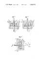
- FIG. 1is a side-sectional view of a canister for a capacitor made according to the principles of the invention
- FIG. 2is a side, partially sectional view of a discoidal monolithic capacitive structure for a capacitor made according to the principles of the invention
- FIG. 3is a side-sectional view of the capacitive structure of FIG. 2 disposed in the canister of FIG. 1;
- FIG. 4is a side-sectional view of the capacitive structure and canister of FIG. 3 into which a connecting material has been introduced;
- FIG. 5is a side-sectional view of the capacitive structure, canister, and connecting material of FIG. 4 during rotation;
- FIG. 6is a side-sectional view of the capacitive structure, canister, and connecting material of FIG. 4 after rotation has been completed;
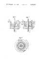
- FIGS. 7 and 8are side-sectional and bottom-sectional views, respectively, of a finished capacitor made in accordance with the principles of the invention.
- FIG. 9is a side-sectional view of a version of a finished capacitor made in accordance with the principles of the invention and incorporating an inductive ring.
- FIG. 1a capacitor canister 8 comprising an electrically conductive cylindrical tube 10, a solid electrically conductive lead forming cylindrical rod 12 running through the interior of tube 10, and an insulative, annular disc closing one end of tube 10 to form between tube 10 and rod 12 a hermetic seal.
- a flange 16is formed at the other end of tube 10.
- Rod 12 and tube 10are centered on an axis 18.
- the inwardly facing cylindrical surface of tube 10 and the outwardly facing cylindrical surface of rod 12form mutually insulated, electrically conductive interior surfaces in canister 8.
- the interior face of disc 14forms an insulative end surface opposite the open end of canister 8.
- the seal between disc 14 and tube 10 and rod 12is formed by well-known techniques.
- the described canistercan be purchased on the open market, for example from Aspe, Inc., of Fairfield, N.J.
- tube 10is made from steel plated with gold for improved surface conductivity
- rod 12is made from Kovar coated with gold for improved surface conductivity
- disc 14is made from clear sealing glass fired to form the seal with tube 10 and rod 12.
- a discoidal, monolithic capacitive structure 20comprises in a one-piece laminated construction a plurality of spaced parallel annular conductive layers 26 joined by an outer cylindrical conductive layer 28, a plurality of spaced parallel annular conductive layers 22 joined by an inner cylindrical conductive layer 24, annular insulative layers 30 sandwiched between conductive layers 22 and 26, and annular insulative layers 32 covering the conductive layers (22 or 26) on the ends of structure 20.
- layers 30 and 32could be a ceramic material such as barium titinate with appropriate additives.
- Structure 20is annular in shape, layer 24 covering most of the inside of the annulus, and layer 28 covering most of the outside of the annulus.
- Layers 22have an outer diameter slightly smaller than structure 20 so that they do not join layer 28 and layers 26 have an inner diameter slightly larger than structure 20 so that they do not join layer 24.
- Layers 22 and 26are disposed adjacent to each other to form parallel pairs of electrically conductive capacitor plates.
- Layer 24forms an electrically conductive bus connecting one plate of each pair, namely layers 22,
- layer 28forms an electrically conductive bus connecting the other plate of each pair, namely layers 26, to the exclusion of the one plate of each pair, namely layers 22.
- layers 22 through 28are typically of the order of six mils or less in thickness
- layers 30 and 32are of the order of one-half mil or less, and as many as 60 or more of each of layers 22 and 26 are provided.
- Structure 20is a commercially available component and its method of construction is well-known in the art. Briefly, a plurality of these structures are generally produced from a single laminate. First, a plurality of thin ceramic films, which comprise the insulative layers, are formed. Next, conductive patterns defining layers 22 and 26 are imprinted on the surfaces of the ceramic films, for example by a silk screening process. Next the insulative layers are stacked to form the laminate. Then, the individual capacitive structures are cut out of the laminate. Finally, layers 24 and 28 are formed on the inner and outer cylindrical surfaces of the structure.
- an annular bead of a bonding agent 34such as uncured epoxy, is deposited on the inner surface of disc 14 around rod 12. Structure 20 is then pushed firmly into bonding agent 34 so the bonding agent is squeezed into the gaps between structure 20 and canister 8, as depicted in FIG. 3. Bonding agent 34 extends a maximum of one-third the length of structure 20 along axis 18. Bonding agent 34 is permitted to set up to secure structure 20 within canister 8 in the manner depicted in FIG. 3.
- bonding agent 34could comprise a two-component epoxy resin, such as MERECO 4583 with hardener #16 which is sold by Mereco Products, Cranston, R.I.
- the bonding agentwould be set up by curing in an oven for approximately 30 minutes at approximately 150° C.
- the inner diameter of structure 20is larger than the diameter of rod 12 and the outer diameter of structure 20 is smaller than the diameter of the inside surface of tube 10.
- the respective buses of structure 20lie adjacent to the respective conductive surfaces of canister 8 in closely spaced relationship to define therewith and the closed end surface of canister 8 two annular cavities in communication with the open end of the canister, but out of direct communication with each other.
- solderto make the electrical connection between the buses of the capacitive structure and the conductive surfaces of the canister.
- a solderless electrical connectionis made between the buses of the capacitive structure and the respective conductive surfaces of the canister in which the capacitive structure is disposed.
- An electrically conductive solidifiable fluidic connecting material 36 having a pasty consistencyis introduced into the open end of canister 8 as depicted in FIG. 4.
- the volume of conductive material 36 introduced into the interior of canister 8exceeds the combined volume of the annular cavities to insure that the quantity of conductive material is sufficient to completely bridge the gaps between the buses of capacitive structure 20 and the conductive surfaces of canister 8.
- conducting material 36is an uncured thermosetting, non-conducting material loaded with electrically conductive particles and the conductive particles have a higher density than the thermosetting material.
- the concentration of conductive particlesis sufficient to establish an electrical connection, i.e., a volume resistivity of less than about 0.0005 ohm-cm.
- Suitable for use as connecting material 36is an electrically conductive polyimide sold by Ablestik Laboratories of Gardena, Calif., under the designation ABLEBOND 71-1, which has the following typical properties:
- the ABLEBONDis injected into canister 8 by means of a microsyringe so that a thick layer of the paste covers the portions of the annular cavities visible to the human eye from the open end of canister 8.
- the viscosity of the pasty connecting materialis too high to flow sufficiently into the annular cavities to establish good electrical connections between capacitive structure 20 and canister 8.
- the capacitor at the state of completion described in connection with FIG. 4,is mounted in a centrifuge so the open end of canister 8 faces the center of rotation of the centrifuge which is designated 40 in FIG. 5.
- axis 18 of cansister 8passes through center of rotation 40.
- the concentration of conductive particlesis greater at the closed end of canister 8 than at the open end thereof, as depicted by the stipling in FIG. 5.
- centrifugingis the preferable way to inject conductive material 36 into the annular cavities because it facilitates manufacture of the described capacitor in production quantities
- other ways of injectionmay be employed.
- conductive material 36may be directly injected into its final position by means of the microsyringe.
- flow of conductive material 36 into the annular cavitiesmay be induced by hammer blows struck against canister 8 parallel to axis 18 in the direction of desired flow.
- Other means of applying impact to canister 8could also be employed to induce flow into the annular cavities.
- the gaps between the conductors of the canistermay be sufficiently large so that the conductive material will flow into its proper position with little or no outside influence.
- connecting material 36is partially or completely cured.
- ABLEBOND 71-1it is partially cured by placing the capacitor in an oven for a minimum of four hours at a temperature of approximately 60° C. and then placing it in an oven for ten minutes at approximately 150° C. Thereafter, the portion of connecting material 36 bridging the gap between the conductive surfaces of canister 8 at its open end is removed, preferably by microblasting. Sufficient connecting material is removed so the end of capacitive structure 20 facing the open end of canister 8 is devoid of the conductive material so no short circuit can develop.
- the conductive materialcould be microblasted by micron-sized sodium bicarbonate in a dry nitrogen carrier gas by means of a Conco Microblaster MB-100 at a pressure setting of 80 to 100 psi.
- a high velocity stream of finely ground sodium bicarbonateis directed with a microtip into the canister until the end of capacitive structure 20 facing the open end of canister 8 is clean.
- Sodium bicarbonateis used for the microblasting operation because it is harder than the conductive material, but softer than the gold plate on canister 8 so as to prevent removal thereof.
- sodium bicarbonateother particulate abrasive material having a hardness between that of the conductive material and the gold plate could be employed for the microblasting operation. If connecting material 36 was previously only partially cured, the curing process is now completed. In the case of ABLEBOND 71-1, the capacitor is placed in an oven for 10 to 12 minutes at a temperature of approximately 275° C.
- a potting material 44is introduced into the open end of canister 8 to fill the remaining space therein and is hardened to complete the capacitor manufacturing method.
- potting material 44could comprise the two-component epoxy system described above as bonding agent 34.
- the finished capacitoris shown in FIGS. 7 and 8.
- bonding agent 34 and potting material 44prevent migration of the conductive particles of connecting material 34 out of the annular cavities during use of the capacitor, which would create danger of either a low insulation resistance condition or a short circuit.
- the described capacitorprovides a reliable, highly heat resistant electrically conductive connection between capacitive structure 20 and the conductive surfaces of canister 8; further the size and thermal mass restrictions heretofore imposed by the danger of solder reflow during component installation have been removed.
- the density of conductive particlesis selectively increased, thereby increasing at least the high frequency admittance of the connection, without adversely affecting the viscosity of the connecting material.
- FIG. 9is shown a version of a finished capacitor incorporating an inductive ring to form with capacitive structure 20 a filter.
- Like elements in FIG. 9bear the same reference numerals as in FIGS. 1 through 8.
- the filter of FIG. 9is made in the manner described in connection with FIGS. 1 through 8, except that inductive ring 46 is embedded in potting material 44 before it is hardened. Potting material 44 insulates inductive ring 46, which is preferably made of a ferrite, from structure 20 and canister 8.
- the centrifuging stepmay be applicable to improve the admittance of an electrical connection for other types of electrically conductive solidifiable fluidic connecting materials.
- the centrifuging stepis necessary to obtain a good electrical connection with currently known and available types of connecting material because of their high viscosity, if suitable connecting materials with lower viscosity and sufficient conductivity become available in the future, the centrifuging step may be eliminated.
Landscapes
- Engineering & Computer Science (AREA)
- Power Engineering (AREA)
- Manufacturing & Machinery (AREA)
- Microelectronics & Electronic Packaging (AREA)
- Fixed Capacitors And Capacitor Manufacturing Machines (AREA)
Abstract
Description
______________________________________ Consistency Very soft, smooth paste Conductor Pure Silver Particles Specific Gravity 2.4 grams/ml Work Life (open time) 8 hours @ RT (25° C.)Cure 10 min. @ 150° and 10 min. @ 275° C. Hardness (Shore D) 82 Volume Resistivity 0.0001 ohm-cm Lap Shear Strength 1000 psi to gold Surface Temperature 350° C. (continuous) Maximum Temperature 500° C. (intermittent) Thermal Conductivity 1.2 BTU/hr-sq ft-deg F/ft or 0.021 Watts/sq cm-deg C/cm ______________________________________
______________________________________ Max. Installation Temperature 300° C. Max. Operating Temperature 200° C. Capacitance 10,000 picofarads (range is 1 pf to 2 mfd) Number of22,26 6 each Thickness of layers 22,26 .1 to .3 mils Number of layers layers 30 11 Thickness oflayers 30 1.6 mils Number oflayers 32 5 Thickness oflayers 32 1.6 mils Inside diameter ofstructure 20 .040 inch Outer diameter ofstructure 20 .127 inch Height ofstructure 20 .035 inch Diameter ofrod 12 .032 inch Inside diameter oftube 10 .140 inch (range is .06 to .750 inch) Thickness oftube 10 .0125 inch Height oftube 10 .150 inch Thickness ofdisc 14 .045 inch ______________________________________
Claims (21)
Priority Applications (1)
| Application Number | Priority Date | Filing Date | Title |
|---|---|---|---|
| US06342497US4424551B1 (en) | 1982-01-25 | 1982-01-25 | Highly-reliable feed through/filter capacitor and method for making same |
Applications Claiming Priority (1)
| Application Number | Priority Date | Filing Date | Title |
|---|---|---|---|
| US06342497US4424551B1 (en) | 1982-01-25 | 1982-01-25 | Highly-reliable feed through/filter capacitor and method for making same |
Publications (2)
| Publication Number | Publication Date |
|---|---|
| US4424551Atrue US4424551A (en) | 1984-01-03 |
| US4424551B1 US4424551B1 (en) | 1991-06-11 |
Family
ID=23342088
Family Applications (1)
| Application Number | Title | Priority Date | Filing Date |
|---|---|---|---|
| US06342497Expired - LifetimeUS4424551B1 (en) | 1982-01-25 | 1982-01-25 | Highly-reliable feed through/filter capacitor and method for making same |
Country Status (1)
| Country | Link |
|---|---|
| US (1) | US4424551B1 (en) |
Cited By (166)
| Publication number | Priority date | Publication date | Assignee | Title |
|---|---|---|---|---|
| US4675632A (en)* | 1984-02-23 | 1987-06-23 | Mitsubishi Denki Kabushiki Kaisha | Coaxial line shape resonator with high dielectric constant |
| US4791391A (en)* | 1983-03-30 | 1988-12-13 | E. I. Du Pont De Nemours And Company | Planar filter connector having thick film capacitors |
| DE4013812A1 (en)* | 1989-05-09 | 1990-11-15 | Avx Corp | HERMETICALLY SEALED ELECTRICAL CONDUCTION WITH ELECTRIC FILTER ELEMENTS IN CHIPFORM |
| EP0433443A4 (en)* | 1989-07-12 | 1992-11-19 | Sundstrand Corporation | High current feed-through capacitor |
| US5333095A (en)* | 1993-05-03 | 1994-07-26 | Maxwell Laboratories, Inc., Sierra Capacitor Filter Division | Feedthrough filter capacitor assembly for human implant |
| WO1995001644A1 (en)* | 1993-07-02 | 1995-01-12 | The Morgan Crucible Company Plc | A high temperature feed-through system and method for making same |
| US5406444A (en)* | 1993-03-29 | 1995-04-11 | Medtronic, Inc. | Coated tantalum feedthrough pin |
| EP0705621A1 (en) | 1994-10-04 | 1996-04-10 | Medtronic, Inc. | Protective feedthrough |
| US5650759A (en)* | 1995-11-09 | 1997-07-22 | Hittman Materials & Medical Components, Inc. | Filtered feedthrough assembly having a mounted chip capacitor for medical implantable devices and method of manufacture therefor |
| US5735884A (en)* | 1994-10-04 | 1998-04-07 | Medtronic, Inc. | Filtered feedthrough assembly for implantable medical device |
| US5751539A (en)* | 1996-04-30 | 1998-05-12 | Maxwell Laboratories, Inc. | EMI filter for human implantable heart defibrillators and pacemakers |
| WO1998030281A1 (en) | 1997-01-06 | 1998-07-16 | Cardiac Pacemakers, Inc. | Filtered feedthrough for an implantable medical device |
| US5817130A (en)* | 1996-05-03 | 1998-10-06 | Sulzer Intermedics Inc. | Implantable cardiac cardioverter/defibrillator with EMI suppression filter with independent ground connection |
| EP0870517A1 (en)* | 1997-04-10 | 1998-10-14 | Hittman Materials and Medical Components, Inc. | Filtered feedthrough assembly for medical implantable devices and method of manufacture therefor |
| US5825608A (en)* | 1996-10-18 | 1998-10-20 | Novacap, Inc. | Feed-through filter capacitor assembly |
| US5867361A (en)* | 1997-05-06 | 1999-02-02 | Medtronic Inc. | Adhesively-bonded capacitive filter feedthrough for implantable medical device |
| US5905627A (en)* | 1997-09-10 | 1999-05-18 | Maxwell Energy Products, Inc. | Internally grounded feedthrough filter capacitor |
| US5959829A (en)* | 1998-02-18 | 1999-09-28 | Maxwell Energy Products, Inc. | Chip capacitor electromagnetic interference filter |
| US5973906A (en)* | 1998-03-17 | 1999-10-26 | Maxwell Energy Products, Inc. | Chip capacitors and chip capacitor electromagnetic interference filters |
| US5999398A (en)* | 1998-06-24 | 1999-12-07 | Avx Corporation | Feed-through filter assembly having varistor and capacitor structure |
| US6008980A (en)* | 1997-11-13 | 1999-12-28 | Maxwell Energy Products, Inc. | Hermetically sealed EMI feedthrough filter capacitor for human implant and other applications |
| WO2000008754A3 (en)* | 1998-08-07 | 2000-06-08 | Epcos Ag | Solderless, coaxial feedthrough component |
| US6141588A (en)* | 1998-07-24 | 2000-10-31 | Intermedics Inc. | Cardiac simulation system having multiple stimulators for anti-arrhythmia therapy |
| US6159560A (en)* | 1998-11-25 | 2000-12-12 | Stevenson; Robert A. | Process for depositing a metal coating on a metallic component of an electrical structure |
| EP1109180A2 (en) | 1999-12-14 | 2001-06-20 | Maxwell Electronic Components Group, Inc. | Emi Filter feedthrough terminal assembly |
| US6275369B1 (en) | 1997-11-13 | 2001-08-14 | Robert A. Stevenson | EMI filter feedthough terminal assembly having a capture flange to facilitate automated assembly |
| US6349025B1 (en)* | 1999-11-30 | 2002-02-19 | Medtronic, Inc. | Leak testable capacitive filtered feedthrough for an implantable medical device |
| US6424234B1 (en) | 1998-09-18 | 2002-07-23 | Greatbatch-Sierra, Inc. | Electromagnetic interference (emi) filter and process for providing electromagnetic compatibility of an electronic device while in the presence of an electromagnetic emitter operating at the same frequency |
| US6456481B1 (en) | 2001-05-31 | 2002-09-24 | Greatbatch-Sierra, Inc. | Integrated EMI filter-DC blocking capacitor |
| US6459935B1 (en) | 2000-07-13 | 2002-10-01 | Avx Corporation | Integrated filter feed-thru |
| US6473291B1 (en) | 1999-03-16 | 2002-10-29 | Gb Aquisition Co., Inc. | Low inductance four terminal capacitor lead frame |
| US6529103B1 (en) | 2000-09-07 | 2003-03-04 | Greatbatch-Sierra, Inc. | Internally grounded feedthrough filter capacitor with improved ground plane design for human implant and other applications |
| US6567259B2 (en) | 2001-05-31 | 2003-05-20 | Greatbatch-Sierra, Inc. | Monolithic ceramic capacitor with barium titinate dielectric curie point optimized for active implantable medical devices operating at 37° C. |
| US20030123215A1 (en)* | 2002-01-02 | 2003-07-03 | Allen Kevin M. | Installation of filter capacitors into feedthroughs for implantable medical devices |
| WO2003073449A1 (en) | 2002-02-28 | 2003-09-04 | Greatbatch-Sierra, Inc. | Emi feedthrough filter terminal assembly for human implant applications utilizing oxide resistant biostable conductive pads for reliable electrical attachments |
| US6643903B2 (en)* | 1997-11-13 | 2003-11-11 | Greatbatch-Sierra, Inc. | Process for manufacturing an EMI filter feedthrough terminal assembly |
| US20040027215A1 (en)* | 2002-08-07 | 2004-02-12 | Carter Mark A. | Electromagnetic interference filter |
| US20040201947A1 (en)* | 2002-02-28 | 2004-10-14 | Stevenson Robert A. | EMI filter capacitors designed for direct body fluid exposure |
| US20040257747A1 (en)* | 2003-05-23 | 2004-12-23 | Stevenson Robert A. | Inductor capacitor EMI filter for human implant applications |
| US20050007718A1 (en)* | 2003-02-27 | 2005-01-13 | Stevenson Robert A. | EMI filter terminal assembly with wire bond pads for human implant applications |
| US6882248B2 (en) | 2000-09-07 | 2005-04-19 | Greatbatch-Sierra, Inc. | EMI filtered connectors using internally grounded feedthrough capacitors |
| US20050092507A1 (en)* | 2003-10-29 | 2005-05-05 | Medtronic, Inc. | Implantable device feedthrough assembly |
| US20050197677A1 (en)* | 2004-02-12 | 2005-09-08 | Stevenson Robert A. | Apparatus and process for reducing the susceptability of active implantable medical devices to medical procedures such as magnetic resonance imaging |
| US20050258511A1 (en)* | 2003-05-06 | 2005-11-24 | Sehat Sutardja | Ultra low inductance multi layer ceramic capacitor |
| US20060023397A1 (en)* | 2004-07-27 | 2006-02-02 | Greatbatch-Sierra, Inc. | Feedthrough capacitor filter assemblies with laminar flow delaminations for helium leak detection |
| US20060028784A1 (en)* | 2004-05-10 | 2006-02-09 | Greatbatch-Sierra, Inc. | Device to protect an active implantable medical device feedthrough capacitor from stray laser weld strikes, and related manufacturing process |
| US20060085043A1 (en)* | 2004-04-15 | 2006-04-20 | Greatbatch-Sierra, Inc. | Apparatus and process for reducing the susceptibility of active implantable medical devices to medical procedures such as magentic resonance imaging |
| US7035076B1 (en) | 2005-08-15 | 2006-04-25 | Greatbatch-Sierra, Inc. | Feedthrough filter capacitor assembly with internally grounded hermetic insulator |
| EP1695736A1 (en) | 2005-02-23 | 2006-08-30 | Greatbatch-Sierra, Inc. | Shielded RF distance telemetry pin for active implantable medical devices |
| US20060212096A1 (en)* | 2005-03-21 | 2006-09-21 | Greatbatch-Sierra, Inc. | Rfid detection and identification system for implantable medical devices |
| US20060247714A1 (en)* | 2005-04-28 | 2006-11-02 | Taylor William J | Glass-to-metal feedthrough seals having improved durability particularly under AC or DC bias |
| US20060259093A1 (en)* | 2003-02-27 | 2006-11-16 | Greatbatch-Sierra, Inc. | Hermetic feedthrough terminal assembly with wire bond pads for human implant applications |
| EP1760735A1 (en) | 2005-09-02 | 2007-03-07 | Wilson Greatbatch Limited | Screen-printed capacitors for filter feedthrough assemblies |
| US20070083244A1 (en)* | 2005-10-06 | 2007-04-12 | Greatbatch-Sierra, Inc. | Process for tuning an emi filter to reduce the amount of heat generated in implanted lead wires during medical procedures such as magnetic resonance imaging |
| US20070088405A1 (en)* | 2005-10-14 | 2007-04-19 | Jacobson Peter M | Programmer for biostimulator system |
| EP1834666A2 (en) | 2006-03-14 | 2007-09-19 | Greatbatch Ltd. | Integrated filter feedthrough assemblies made from low temperature co-fired (LTCC) tape |
| US20070234540A1 (en)* | 2006-03-31 | 2007-10-11 | Iyer Rajesh V | A method of attaching a capacitor to a feedthrough assembly of a medical device |
| US20070260282A1 (en)* | 2003-09-12 | 2007-11-08 | Taylor William J | Feedthrough apparatus with noble metal-coated leads |
| US20070279834A1 (en)* | 2006-06-01 | 2007-12-06 | Greatbatch, Ltd. | Feedthrough capacitor having reduced self resonance insertion loss dip |
| US20070279833A1 (en)* | 2005-12-29 | 2007-12-06 | Iyer Rajesh V | Filtered feedthrough assembly and method of manufacture |
| US20080036556A1 (en)* | 2006-08-10 | 2008-02-14 | Honeywell International Inc. | Methods and apparatus for installing a feed through filter |
| US20080071313A1 (en)* | 2005-11-11 | 2008-03-20 | Greatbatch Ltd. | Tank filters utilizing very low k materials, in series with lead wires or circuits of active medical devices to enhance mri compatibility |
| US7391601B1 (en) | 2006-07-12 | 2008-06-24 | Pacesetter, Inc. | Feedthrough filter assembly |
| US20080161886A1 (en)* | 2006-06-08 | 2008-07-03 | Greatbatch Ltd. | Tank filters adaptable for placement with a guide wire, in series with the lead wires or circuits of active medical devices to enhance mri compatibility |
| US20080180878A1 (en)* | 2007-01-31 | 2008-07-31 | Advanced Semiconductor Engineering, Inc. | Package structure with embedded capacitor, fabricating process thereof and applications of the same |
| US20080294220A1 (en)* | 2006-04-03 | 2008-11-27 | Greatbatch Ltd. | Feedthrough filter terminal assemblies with breathable components to facilitate leak testing |
| US20090079517A1 (en)* | 2007-09-25 | 2009-03-26 | Iyer Rajesh V | Novel capacitive elements and filtered feedthrough elements for implantable medical devices |
| US20090079518A1 (en)* | 2007-09-25 | 2009-03-26 | Iyer Rajesh V | Novel capacitive elements and filtered feedthrough elements for implantable medical devices |
| US20090082828A1 (en)* | 2007-09-20 | 2009-03-26 | Alan Ostroff | Leadless Cardiac Pacemaker with Secondary Fixation Capability |
| US20090116167A1 (en)* | 2002-02-28 | 2009-05-07 | Greatbatch Ltd. | Passive electronic network components designed for direct body fluid exposure |
| EP2062525A2 (en) | 2007-11-20 | 2009-05-27 | Greatbatch Ltd. | RFID detection and identification system for implantable medical lead systems |
| US20090163974A1 (en)* | 2003-09-12 | 2009-06-25 | Medtronic, Inc. | Feedthrough apparatus with noble metal-coated leads |
| WO2009081663A1 (en)* | 2007-12-21 | 2009-07-02 | Murata Manufacturing Co., Ltd. | Band elimination filter and connector provided with band elimination filter |
| US20090229858A1 (en)* | 2006-11-30 | 2009-09-17 | William John Taylor | Insulator for feedthrough |
| WO2009117599A2 (en) | 2008-03-20 | 2009-09-24 | Greatbatch Ltd. | Shielded three-terminal flat-through emi/energy dissipating filter |
| US20090259265A1 (en)* | 2002-02-28 | 2009-10-15 | Greatbatch Ltd. | Electronic network components utilizing biocompatible conductive adhesives for direct body fluid exposure |
| WO2009128310A1 (en)* | 2008-04-18 | 2009-10-22 | 株式会社村田製作所 | Functional substrate |
| US20090288280A1 (en)* | 2008-05-22 | 2009-11-26 | Greatbatch Ltd. | Process for manufacturing emi filters utilizing counter-bored capacitors to facilitate solder re-flow |
| US20090321107A1 (en)* | 2006-11-30 | 2009-12-31 | Medtronic, Inc. | Feedthrough assembly and associated method |
| US20100016936A1 (en)* | 2001-04-13 | 2010-01-21 | Greatbatch Ltd. | Frequency selective passive component networks for implantable leads of active implantable medical devices utilizing an energy dissipating surface |
| US20100023000A1 (en)* | 2002-04-15 | 2010-01-28 | Greatbatch Ltd. | Frequency selective passive component networks for implantable leads of active implantable medical devices utilizing an energy dissipating surface |
| US20100060431A1 (en)* | 2006-01-25 | 2010-03-11 | Greatbatch Ltd. | Miniature hermetically sealed rfid microelectronic chip connected to a biocompatible rfid antenna for use in conjunction with an aimd |
| US20100123547A1 (en)* | 2008-11-19 | 2010-05-20 | Greatbatch Ltd. | Rfid detection and identification system including an rfid reader having a limited transmit time and a time-out period to protect a medical device against rfid-associated electromagnetic interference |
| US20100134951A1 (en)* | 2008-11-12 | 2010-06-03 | Greatbatch Ltd. | Electromagnetic interference filter and method for attaching a lead and/or a ferrule to capacitor electrodes |
| US20100160997A1 (en)* | 2001-04-13 | 2010-06-24 | Greatbatch Ltd. | Tuned energy balanced system for minimizing heating and/or to provide emi protection of implanted leads in a high power electromagnetic field environment |
| US20100168821A1 (en)* | 2001-04-13 | 2010-07-01 | Greatbatch Ltd. | Switched diverter circuits for minimizing heating of an implanted lead in a high power electromagnetic field environment |
| US20100177458A1 (en)* | 2009-01-12 | 2010-07-15 | Medtronic, Inc. | Capacitor for filtered feedthrough with conductive pad |
| WO2010081139A1 (en) | 2009-01-12 | 2010-07-15 | Medtronic, Inc. | Capacitor for filtered feedthrough with conductive pad |
| US20100185263A1 (en)* | 2008-03-20 | 2010-07-22 | Greatbatch Ltd. | Rf activated aimd telemetry transceiver |
| US20100191306A1 (en)* | 2006-01-25 | 2010-07-29 | Greatbatch Ltd. | Transient voltage suppression circuit for an implanted rfid chip |
| US20100191236A1 (en)* | 2001-04-13 | 2010-07-29 | Greatbatch Ltd. | Switched diverter circuits for minimizing heating of an implanted lead and/or providing emi protection in a high power electromagnetic field environment |
| US20100194541A1 (en)* | 2006-01-25 | 2010-08-05 | Greatbatch Ltd. | Hermetically sealed rfid microelectronic chip connected to a biocompatible rfid antenna |
| US20100198288A1 (en)* | 2009-02-02 | 2010-08-05 | Alan Ostroff | Leadless Cardiac Pacemaker with Secondary Fixation Capability |
| US20100202096A1 (en)* | 2009-02-10 | 2010-08-12 | Medtronic, Inc. | Filtered feedthrough assembly and associated method |
| US20100208397A1 (en)* | 2008-12-17 | 2010-08-19 | Greatbatch Ltd. | Switched safety protection circuit for an aimd system during exposure to high power electromagnetic fields |
| US20100241206A1 (en)* | 2009-03-19 | 2010-09-23 | Greatbatch Ltd. | Emi shielded conduit assembly for an active implantable medical device |
| US20100284124A1 (en)* | 2009-05-06 | 2010-11-11 | Medtronic, Inc. | Capacitor assembly and associated method |
| US20100302702A1 (en)* | 2009-06-02 | 2010-12-02 | Astec International Limited | Feedthrough Capacitor Assemblies |
| US20110003521A1 (en)* | 2009-07-01 | 2011-01-06 | Roman Kendyl A | Clean energy powered surfboards |
| US20110032658A1 (en)* | 2009-08-07 | 2011-02-10 | Medtronic, Inc. | Capacitor assembly and associated method |
| US20110077708A1 (en)* | 2009-09-28 | 2011-03-31 | Alan Ostroff | MRI Compatible Leadless Cardiac Pacemaker |
| US20110125210A1 (en)* | 2009-11-24 | 2011-05-26 | Medtronic, Inc. | Ltcc/htcc hybrid feedthrough |
| US20110147062A1 (en)* | 2009-12-22 | 2011-06-23 | Greatbatch Ltd. | Feedthrough flat-through capacitor |
| US20110230943A1 (en)* | 2010-03-17 | 2011-09-22 | Greatbatch Ltd. | Implantable lead for an active medical device having an inductor design minimizing eddy current losses |
| EP2392382A1 (en) | 2005-11-11 | 2011-12-07 | Greatbatch Ltd. | Tank filters placed in series with the lead wires or circuits of active medical devices to enhance MRI compatibility |
| US20120205150A1 (en)* | 2011-02-10 | 2012-08-16 | Litronik Entwicklungs Gmbh | Feedthrough conductor for electronic components |
| EP2497532A2 (en) | 2011-03-07 | 2012-09-12 | Greatbatch Ltd. | Secondary header for an implantable medical device incorporating an ISO DF4 connector and connector cavity and/or an IS4 connector and connector cavity |
| US8543205B2 (en) | 2010-10-12 | 2013-09-24 | Nanostim, Inc. | Temperature sensor for a leadless cardiac pacemaker |
| US8593816B2 (en) | 2011-09-21 | 2013-11-26 | Medtronic, Inc. | Compact connector assembly for implantable medical device |
| US8615310B2 (en) | 2010-12-13 | 2013-12-24 | Pacesetter, Inc. | Delivery catheter systems and methods |
| US8644936B2 (en) | 2012-01-09 | 2014-02-04 | Medtronic, Inc. | Feedthrough assembly including electrical ground through feedthrough substrate |
| US8644002B2 (en) | 2011-05-31 | 2014-02-04 | Medtronic, Inc. | Capacitor including registration feature for aligning an insulator layer |
| US8653384B2 (en) | 2012-01-16 | 2014-02-18 | Greatbatch Ltd. | Co-fired hermetically sealed feedthrough with alumina substrate and platinum filled via for an active implantable medical device |
| US8659870B2 (en) | 2010-11-22 | 2014-02-25 | Greatbatch Ltd. | Modular EMI filtered terminal assembly for an active implantable medical device |
| US8844103B2 (en) | 2011-09-01 | 2014-09-30 | Medtronic, Inc. | Methods for making feedthrough assemblies including a capacitive filter array |
| US8882763B2 (en) | 2010-01-12 | 2014-11-11 | Greatbatch Ltd. | Patient attached bonding strap for energy dissipation from a probe or a catheter during magnetic resonance imaging |
| US8903505B2 (en) | 2006-06-08 | 2014-12-02 | Greatbatch Ltd. | Implantable lead bandstop filter employing an inductive coil with parasitic capacitance to enhance MRI compatibility of active medical devices |
| US9020611B2 (en) | 2010-10-13 | 2015-04-28 | Pacesetter, Inc. | Leadless cardiac pacemaker with anti-unscrewing feature |
| US9060692B2 (en) | 2010-10-12 | 2015-06-23 | Pacesetter, Inc. | Temperature sensor for a leadless cardiac pacemaker |
| US9093974B2 (en) | 2012-09-05 | 2015-07-28 | Avx Corporation | Electromagnetic interference filter for implanted electronics |
| US9101782B2 (en) | 2011-08-19 | 2015-08-11 | Greatbatch Ltd. | Implantable cardioverter defibrillator designed for use in a magnetic resonance imaging environment |
| US9108066B2 (en) | 2008-03-20 | 2015-08-18 | Greatbatch Ltd. | Low impedance oxide resistant grounded capacitor for an AIMD |
| US9126032B2 (en) | 2010-12-13 | 2015-09-08 | Pacesetter, Inc. | Pacemaker retrieval systems and methods |
| US9168383B2 (en) | 2005-10-14 | 2015-10-27 | Pacesetter, Inc. | Leadless cardiac pacemaker with conducted communication |
| US9242102B2 (en) | 2010-12-20 | 2016-01-26 | Pacesetter, Inc. | Leadless pacemaker with radial fixation mechanism |
| US20160055976A1 (en)* | 2014-08-25 | 2016-02-25 | Qualcomm Incorporated | Package substrates including embedded capacitors |
| US9295828B2 (en) | 2001-04-13 | 2016-03-29 | Greatbatch Ltd. | Self-resonant inductor wound portion of an implantable lead for enhanced MRI compatibility of active implantable medical devices |
| US9427596B2 (en) | 2013-01-16 | 2016-08-30 | Greatbatch Ltd. | Low impedance oxide resistant grounded capacitor for an AIMD |
| US9463329B2 (en) | 2008-03-20 | 2016-10-11 | Greatbatch Ltd. | Shielded three-terminal flat-through EMI/energy dissipating filter with co-fired hermetically sealed feedthrough |
| US9504843B2 (en) | 2011-08-19 | 2016-11-29 | Greatbach Ltd. | Implantable cardioverter defibrillator designed for use in a magnetic resonance imaging environment |
| US9511236B2 (en) | 2011-11-04 | 2016-12-06 | Pacesetter, Inc. | Leadless cardiac pacemaker with integral battery and redundant welds |
| WO2017101992A1 (en)* | 2015-12-16 | 2017-06-22 | Siemens Aktiengesellschaft | High-voltage apparatus and method for producing same |
| US9802054B2 (en) | 2012-08-01 | 2017-10-31 | Pacesetter, Inc. | Biostimulator circuit with flying cell |
| USRE46699E1 (en) | 2013-01-16 | 2018-02-06 | Greatbatch Ltd. | Low impedance oxide resistant grounded capacitor for an AIMD |
| US9889306B2 (en) | 2012-01-16 | 2018-02-13 | Greatbatch Ltd. | Hermetically sealed feedthrough with co-fired filled via and conductive insert for an active implantable medical device |
| US9931514B2 (en) | 2013-06-30 | 2018-04-03 | Greatbatch Ltd. | Low impedance oxide resistant grounded capacitor for an AIMD |
| EP3320950A1 (en) | 2016-11-10 | 2018-05-16 | Greatbatch Ltd. | Feedthrough assembly for active implantable medical device |
| EP3326692A1 (en) | 2016-11-08 | 2018-05-30 | Greatbatch Ltd. | Feedthrough for an implantable medical device having a composite conductive lead |
| EP3345652A1 (en) | 2017-01-06 | 2018-07-11 | Greatbatch Ltd. | Method for manufacturing a feedthrough for an active implantable medical device |
| US10046166B2 (en) | 2012-01-16 | 2018-08-14 | Greatbatch Ltd. | EMI filtered co-connected hermetic feedthrough, feedthrough capacitor and leadwire assembly for an active implantable medical device |
| US10080889B2 (en) | 2009-03-19 | 2018-09-25 | Greatbatch Ltd. | Low inductance and low resistance hermetically sealed filtered feedthrough for an AIMD |
| US10249415B2 (en) | 2017-01-06 | 2019-04-02 | Greatbatch Ltd. | Process for manufacturing a leadless feedthrough for an active implantable medical device |
| US10350421B2 (en) | 2013-06-30 | 2019-07-16 | Greatbatch Ltd. | Metallurgically bonded gold pocket pad for grounding an EMI filter to a hermetic terminal for an active implantable medical device |
| US10376690B2 (en) | 2014-08-26 | 2019-08-13 | Medtronic, Inc. | Interventional medical systems, devices, and components thereof |
| US10420949B2 (en) | 2012-01-16 | 2019-09-24 | Greatbatch Ltd. | Method of manufacturing a feedthrough insulator for an active implantable medical device incorporating a post conductive paste filled pressing step |
| US10449375B2 (en) | 2016-12-22 | 2019-10-22 | Greatbatch Ltd. | Hermetic terminal for an AIMD having a pin joint in a feedthrough capacitor or circuit board |
| US10478620B2 (en) | 2014-08-26 | 2019-11-19 | Medtronic, Inc. | Interventional medical systems, devices, and methods of use |
| EP3569284A1 (en) | 2018-05-18 | 2019-11-20 | Greatbatch Ltd. | An aimd rf switch to connect an icd defibrillation electrode conductor either to a filter capacitor or to an rf source configured to detect a defective lead conductor |
| US10561837B2 (en) | 2011-03-01 | 2020-02-18 | Greatbatch Ltd. | Low equivalent series resistance RF filter for an active implantable medical device utilizing a ceramic reinforced metal composite filled via |
| US10828498B2 (en) | 2018-05-18 | 2020-11-10 | Greatbatch Ltd. | AIMD RF switch to connect an ICD defibrillation electrode conductor either to a filter capacitor or to an RF source configured to detect a defective implanted lead |
| US10874865B2 (en) | 2017-11-06 | 2020-12-29 | Avx Corporation | EMI feedthrough filter terminal assembly containing a resin coating over a hermetically sealing material |
| US10881867B2 (en) | 2012-01-16 | 2021-01-05 | Greatbatch Ltd. | Method for providing a hermetically sealed feedthrough with co-fired filled via for an active implantable medical device |
| US10903811B2 (en) | 2017-08-18 | 2021-01-26 | Avx Corporation | Coaxial RF filter with discoidal capacitor |
| US10905888B2 (en) | 2018-03-22 | 2021-02-02 | Greatbatch Ltd. | Electrical connection for an AIMD EMI filter utilizing an anisotropic conductive layer |
| US10912945B2 (en) | 2018-03-22 | 2021-02-09 | Greatbatch Ltd. | Hermetic terminal for an active implantable medical device having a feedthrough capacitor partially overhanging a ferrule for high effective capacitance area |
| US11147977B2 (en) | 2008-03-20 | 2021-10-19 | Greatbatch Ltd. | MLCC filter on an aimd circuit board conductively connected to a ground pin attached to a hermetic feedthrough ferrule |
| EP3900780A1 (en) | 2020-04-21 | 2021-10-27 | Greatbatch Ltd. | An aimd rf switch to connect an icd defibrillation electrode conductor either to a filter capacitor or to an rf source configured to detect a defective implanted lead |
| US11198014B2 (en) | 2011-03-01 | 2021-12-14 | Greatbatch Ltd. | Hermetically sealed filtered feedthrough assembly having a capacitor with an oxide resistant electrical connection to an active implantable medical device housing |
| US11211741B2 (en) | 2011-06-03 | 2021-12-28 | Greatbatch Ltd. | Removable terminal pin connector for an active electronics circuit board for use in an implantable medical device |
| US11541233B2 (en) | 2013-06-30 | 2023-01-03 | Greatbatch Ltd. | ECA oxide-resistant connection to a hermetic seal ferrule for an active implantable medical device |
| US11633612B2 (en) | 2020-02-21 | 2023-04-25 | Greatbatch Ltd. | ECA oxide-resistant connection to a hermetic seal ferrule for an active implantable medical device |
| US20230260714A1 (en)* | 2022-02-17 | 2023-08-17 | Tdk Corporation | High-voltage feed-through capacitor |
| EP4349397A1 (en) | 2022-10-07 | 2024-04-10 | Greatbatch Ltd. | High-voltage electrical insulation for use in active implantable medical devices circuit board connectors |
| US12017065B2 (en) | 2020-05-08 | 2024-06-25 | Greatbatch Ltd. | Electrically conductive coating applied to an oxidizable surface of an AIMD ferrule or housing to provide an oxide-resistant connection to an EMI filter capacitor, an EMI filter circuit or AIMD electronic circuits and components |
| US12218458B2 (en) | 2020-03-05 | 2025-02-04 | Greatbatch Ltd. | High-voltage electrical insulation for use in active implantable medical devices circuit board connectors |
| US20250246342A1 (en)* | 2024-01-31 | 2025-07-31 | Integrated Microwave Corporation | Ceramic rf feedthrough component |
Citations (6)
| Publication number | Priority date | Publication date | Assignee | Title |
|---|---|---|---|---|
| US3266121A (en) | 1963-02-14 | 1966-08-16 | Illinois Tool Works | Method of making a capacitorresistor construction |
| US3538464A (en) | 1963-08-20 | 1970-11-03 | Erie Technological Prod Inc | Multiple pin connector having ferrite core stacked capacitor filter |
| US4041587A (en) | 1975-06-11 | 1977-08-16 | Siemens Aktiengesellschaft | Method of producing layer capacitors |
| DE2815118A1 (en) | 1977-04-07 | 1978-10-19 | Murata Manufacturing Co | FEED-THROUGH CAPACITOR |
| US4148003A (en) | 1977-07-08 | 1979-04-03 | Globe-Union Inc. | Series feed-through capacitor |
| US4314213A (en) | 1978-03-30 | 1982-02-02 | Murata Manufacturing Co., Ltd. | Through-type capacitor |
- 1982
- 1982-01-25USUS06342497patent/US4424551B1/ennot_activeExpired - Lifetime
Patent Citations (6)
| Publication number | Priority date | Publication date | Assignee | Title |
|---|---|---|---|---|
| US3266121A (en) | 1963-02-14 | 1966-08-16 | Illinois Tool Works | Method of making a capacitorresistor construction |
| US3538464A (en) | 1963-08-20 | 1970-11-03 | Erie Technological Prod Inc | Multiple pin connector having ferrite core stacked capacitor filter |
| US4041587A (en) | 1975-06-11 | 1977-08-16 | Siemens Aktiengesellschaft | Method of producing layer capacitors |
| DE2815118A1 (en) | 1977-04-07 | 1978-10-19 | Murata Manufacturing Co | FEED-THROUGH CAPACITOR |
| US4148003A (en) | 1977-07-08 | 1979-04-03 | Globe-Union Inc. | Series feed-through capacitor |
| US4314213A (en) | 1978-03-30 | 1982-02-02 | Murata Manufacturing Co., Ltd. | Through-type capacitor |
Cited By (373)
| Publication number | Priority date | Publication date | Assignee | Title |
|---|---|---|---|---|
| US4791391A (en)* | 1983-03-30 | 1988-12-13 | E. I. Du Pont De Nemours And Company | Planar filter connector having thick film capacitors |
| US4675632A (en)* | 1984-02-23 | 1987-06-23 | Mitsubishi Denki Kabushiki Kaisha | Coaxial line shape resonator with high dielectric constant |
| DE4013812A1 (en)* | 1989-05-09 | 1990-11-15 | Avx Corp | HERMETICALLY SEALED ELECTRICAL CONDUCTION WITH ELECTRIC FILTER ELEMENTS IN CHIPFORM |
| DE4013812C2 (en)* | 1989-05-09 | 2000-06-21 | Avx Corp | Process for producing an airtight sealed electronic component package |
| EP0433443A4 (en)* | 1989-07-12 | 1992-11-19 | Sundstrand Corporation | High current feed-through capacitor |
| DE4410055B4 (en)* | 1993-03-29 | 2005-04-28 | Medtronic Inc | Method for producing an electrical feedthrough |
| US5406444A (en)* | 1993-03-29 | 1995-04-11 | Medtronic, Inc. | Coated tantalum feedthrough pin |
| US5531003A (en)* | 1993-03-29 | 1996-07-02 | Medtronic, Inc. | Fabricating a combination feedthrough/capacitor including a metallized tantalum or niobium pin |
| US5333095A (en)* | 1993-05-03 | 1994-07-26 | Maxwell Laboratories, Inc., Sierra Capacitor Filter Division | Feedthrough filter capacitor assembly for human implant |
| WO1995001644A1 (en)* | 1993-07-02 | 1995-01-12 | The Morgan Crucible Company Plc | A high temperature feed-through system and method for making same |
| US5440447A (en)* | 1993-07-02 | 1995-08-08 | The Morgan Crucible Company, Plc | High temperature feed-through system and method for making same |
| AU680515B2 (en)* | 1993-07-02 | 1997-07-31 | Morgan Crucible Company Plc, The | A high temperature feed-through system and method for making same |
| EP0705621A1 (en) | 1994-10-04 | 1996-04-10 | Medtronic, Inc. | Protective feedthrough |
| US5759197A (en)* | 1994-10-04 | 1998-06-02 | Medtronic, Inc. | Protective feedthrough |
| US5735884A (en)* | 1994-10-04 | 1998-04-07 | Medtronic, Inc. | Filtered feedthrough assembly for implantable medical device |
| US5650759A (en)* | 1995-11-09 | 1997-07-22 | Hittman Materials & Medical Components, Inc. | Filtered feedthrough assembly having a mounted chip capacitor for medical implantable devices and method of manufacture therefor |
| US5751539A (en)* | 1996-04-30 | 1998-05-12 | Maxwell Laboratories, Inc. | EMI filter for human implantable heart defibrillators and pacemakers |
| US5817130A (en)* | 1996-05-03 | 1998-10-06 | Sulzer Intermedics Inc. | Implantable cardiac cardioverter/defibrillator with EMI suppression filter with independent ground connection |
| US5825608A (en)* | 1996-10-18 | 1998-10-20 | Novacap, Inc. | Feed-through filter capacitor assembly |
| WO1998030281A1 (en) | 1997-01-06 | 1998-07-16 | Cardiac Pacemakers, Inc. | Filtered feedthrough for an implantable medical device |
| US6055455A (en)* | 1997-01-06 | 2000-04-25 | Cardiac Pacemakers, Inc. | Filtered feedthrough for an implantable medical device |
| EP0870517A1 (en)* | 1997-04-10 | 1998-10-14 | Hittman Materials and Medical Components, Inc. | Filtered feedthrough assembly for medical implantable devices and method of manufacture therefor |
| US6031710A (en)* | 1997-05-06 | 2000-02-29 | Medtronic, Inc. | Adhesively- and solder-bonded capacitive filter feedthrough for implantable medical devices |
| FR2766719A1 (en) | 1997-05-06 | 1999-02-05 | Medtronic Inc | CAPACITIVE FILTER CROSSOVER FOR AN IMPLANTABLE MEDICAL DEVICE |
| US5870272A (en)* | 1997-05-06 | 1999-02-09 | Medtronic Inc. | Capacitive filter feedthrough for implantable medical device |
| US5867361A (en)* | 1997-05-06 | 1999-02-02 | Medtronic Inc. | Adhesively-bonded capacitive filter feedthrough for implantable medical device |
| DE19819797C2 (en)* | 1997-05-06 | 2002-11-21 | Medtronic Inc | Feedthrough assembly for an implantable medical device |
| US5905627A (en)* | 1997-09-10 | 1999-05-18 | Maxwell Energy Products, Inc. | Internally grounded feedthrough filter capacitor |
| EP0916364A3 (en)* | 1997-11-13 | 2005-04-06 | Greatbatch-Sierra, Inc. | Hermetically sealed emi feedthrough filter capacitor for human implant and other applications |
| US6008980A (en)* | 1997-11-13 | 1999-12-28 | Maxwell Energy Products, Inc. | Hermetically sealed EMI feedthrough filter capacitor for human implant and other applications |
| US6643903B2 (en)* | 1997-11-13 | 2003-11-11 | Greatbatch-Sierra, Inc. | Process for manufacturing an EMI filter feedthrough terminal assembly |
| US6275369B1 (en) | 1997-11-13 | 2001-08-14 | Robert A. Stevenson | EMI filter feedthough terminal assembly having a capture flange to facilitate automated assembly |
| US5959829A (en)* | 1998-02-18 | 1999-09-28 | Maxwell Energy Products, Inc. | Chip capacitor electromagnetic interference filter |
| US5973906A (en)* | 1998-03-17 | 1999-10-26 | Maxwell Energy Products, Inc. | Chip capacitors and chip capacitor electromagnetic interference filters |
| WO1999067796A1 (en)* | 1998-06-24 | 1999-12-29 | Avx Corporation | Feed-through filter assembly |
| US5999398A (en)* | 1998-06-24 | 1999-12-07 | Avx Corporation | Feed-through filter assembly having varistor and capacitor structure |
| US6141588A (en)* | 1998-07-24 | 2000-10-31 | Intermedics Inc. | Cardiac simulation system having multiple stimulators for anti-arrhythmia therapy |
| US6501638B1 (en) | 1998-08-07 | 2002-12-31 | Epcos Ag | Solderless, coaxial feedthrough component |
| WO2000008754A3 (en)* | 1998-08-07 | 2000-06-08 | Epcos Ag | Solderless, coaxial feedthrough component |
| US6424234B1 (en) | 1998-09-18 | 2002-07-23 | Greatbatch-Sierra, Inc. | Electromagnetic interference (emi) filter and process for providing electromagnetic compatibility of an electronic device while in the presence of an electromagnetic emitter operating at the same frequency |
| US6159560A (en)* | 1998-11-25 | 2000-12-12 | Stevenson; Robert A. | Process for depositing a metal coating on a metallic component of an electrical structure |
| US6473291B1 (en) | 1999-03-16 | 2002-10-29 | Gb Aquisition Co., Inc. | Low inductance four terminal capacitor lead frame |
| US6349025B1 (en)* | 1999-11-30 | 2002-02-19 | Medtronic, Inc. | Leak testable capacitive filtered feedthrough for an implantable medical device |
| DE10059373B4 (en)* | 1999-11-30 | 2013-09-19 | Medtronic, Inc. | Leak test, capacitively filtered feedthrough for an implantable medical device |
| EP1109180A2 (en) | 1999-12-14 | 2001-06-20 | Maxwell Electronic Components Group, Inc. | Emi Filter feedthrough terminal assembly |
| US6459935B1 (en) | 2000-07-13 | 2002-10-01 | Avx Corporation | Integrated filter feed-thru |
| US6529103B1 (en) | 2000-09-07 | 2003-03-04 | Greatbatch-Sierra, Inc. | Internally grounded feedthrough filter capacitor with improved ground plane design for human implant and other applications |
| US6882248B2 (en) | 2000-09-07 | 2005-04-19 | Greatbatch-Sierra, Inc. | EMI filtered connectors using internally grounded feedthrough capacitors |
| US6566978B2 (en) | 2000-09-07 | 2003-05-20 | Greatbatch-Sierra, Inc. | Feedthrough capacitor filter assemblies with leak detection vents |
| EP2273518A2 (en) | 2000-09-07 | 2011-01-12 | Greatbatch Ltd. | Internally grounded feedthrough filter capacitor with improved ground plane design for human implant and other applications |
| US8855785B1 (en) | 2001-04-13 | 2014-10-07 | Greatbatch Ltd. | Circuits for minimizing heating of an implanted lead and/or providing EMI protection in a high power electromagnetic field environment |
| US8751013B2 (en) | 2001-04-13 | 2014-06-10 | Greatbatch Ltd. | Switched diverter circuits for minimizing heating of an implanted lead and/or providing EMI protection in a high power electromagnetic field environment |
| US20100191236A1 (en)* | 2001-04-13 | 2010-07-29 | Greatbatch Ltd. | Switched diverter circuits for minimizing heating of an implanted lead and/or providing emi protection in a high power electromagnetic field environment |
| US20100160997A1 (en)* | 2001-04-13 | 2010-06-24 | Greatbatch Ltd. | Tuned energy balanced system for minimizing heating and/or to provide emi protection of implanted leads in a high power electromagnetic field environment |
| US8457760B2 (en) | 2001-04-13 | 2013-06-04 | Greatbatch Ltd. | Switched diverter circuits for minimizing heating of an implanted lead and/or providing EMI protection in a high power electromagnetic field environment |
| US8509913B2 (en) | 2001-04-13 | 2013-08-13 | Greatbatch Ltd. | Switched diverter circuits for minimizing heating of an implanted lead and/or providing EMI protection in a high power electromagnetic field environment |
| US7689288B2 (en) | 2001-04-13 | 2010-03-30 | Greatbatch Ltd. | Frequency selective passive component networks for implantable leads of active implantable medical devices utilizing an energy dissipating surface |
| US20100168821A1 (en)* | 2001-04-13 | 2010-07-01 | Greatbatch Ltd. | Switched diverter circuits for minimizing heating of an implanted lead in a high power electromagnetic field environment |
| US20100016936A1 (en)* | 2001-04-13 | 2010-01-21 | Greatbatch Ltd. | Frequency selective passive component networks for implantable leads of active implantable medical devices utilizing an energy dissipating surface |
| US9295828B2 (en) | 2001-04-13 | 2016-03-29 | Greatbatch Ltd. | Self-resonant inductor wound portion of an implantable lead for enhanced MRI compatibility of active implantable medical devices |
| US9248283B2 (en) | 2001-04-13 | 2016-02-02 | Greatbatch Ltd. | Band stop filter comprising an inductive component disposed in a lead wire in series with an electrode |
| US8989870B2 (en) | 2001-04-13 | 2015-03-24 | Greatbatch Ltd. | Tuned energy balanced system for minimizing heating and/or to provide EMI protection of implanted leads in a high power electromagnetic field environment |
| US6567259B2 (en) | 2001-05-31 | 2003-05-20 | Greatbatch-Sierra, Inc. | Monolithic ceramic capacitor with barium titinate dielectric curie point optimized for active implantable medical devices operating at 37° C. |
| US6456481B1 (en) | 2001-05-31 | 2002-09-24 | Greatbatch-Sierra, Inc. | Integrated EMI filter-DC blocking capacitor |
| US6920673B2 (en)* | 2002-01-02 | 2005-07-26 | Greatbatch-Hittman, Inc. | Installation of filter capacitors into feedthroughs for implantable medical devices |
| US20030123215A1 (en)* | 2002-01-02 | 2003-07-03 | Allen Kevin M. | Installation of filter capacitors into feedthroughs for implantable medical devices |
| US8660645B2 (en) | 2002-02-28 | 2014-02-25 | Greatbatch Ltd. | Electronic network components utilizing biocompatible conductive adhesives for direct body fluid exposure |
| US6765780B2 (en) | 2002-02-28 | 2004-07-20 | Greatbatch-Sierra, Inc. | EMI feedthrough filter terminal assembly having surface mounted, internally grounded hybrid capacitor |
| US20090259265A1 (en)* | 2002-02-28 | 2009-10-15 | Greatbatch Ltd. | Electronic network components utilizing biocompatible conductive adhesives for direct body fluid exposure |
| US6888715B2 (en) | 2002-02-28 | 2005-05-03 | Greatbatch-Sierra, Inc. | EMI feedthrough filter terminal assembly utilizing hermetic seal for electrical attachment between lead wires and capacitor |
| US7535693B2 (en)* | 2002-02-28 | 2009-05-19 | Greatbatch-Sierra, Inc. | EMI filters designed for direct body fluid exposure |
| US20090116167A1 (en)* | 2002-02-28 | 2009-05-07 | Greatbatch Ltd. | Passive electronic network components designed for direct body fluid exposure |
| US20070019362A1 (en)* | 2002-02-28 | 2007-01-25 | Greatbatch-Sierra, Inc. | Emi filters designed for direct body fluid exposure |
| WO2003073449A1 (en) | 2002-02-28 | 2003-09-04 | Greatbatch-Sierra, Inc. | Emi feedthrough filter terminal assembly for human implant applications utilizing oxide resistant biostable conductive pads for reliable electrical attachments |
| US20040201947A1 (en)* | 2002-02-28 | 2004-10-14 | Stevenson Robert A. | EMI filter capacitors designed for direct body fluid exposure |
| US6765779B2 (en) | 2002-02-28 | 2004-07-20 | Greatbatch-Sierra, Inc. | EMI feedthrough filter terminal assembly for human implant applications utilizing oxide resistant biostable conductive pads for reliable electrical attachments |
| US6985347B2 (en) | 2002-02-28 | 2006-01-10 | Greatbatch-Sierra, Inc. | EMI filter capacitors designed for direct body fluid exposure |
| WO2003073450A1 (en) | 2002-02-28 | 2003-09-04 | Greatbatch-Sierra, Inc. | Emi feedthrough filter terminal assembly utilizing hermetic seal for electrical attachment between lead wires and capacitor |
| US7113387B2 (en) | 2002-02-28 | 2006-09-26 | Greatbatch-Sierra, Inc. | EMI filter capacitors designed for direct body fluid exposure |
| US20030179536A1 (en)* | 2002-02-28 | 2003-09-25 | Stevenson Robert A. | EMI feedthrough filter terminal assembly for human implant applications utilizing oxide resistant biostable conductive pads for reliable electrical attachments |
| US20030213604A1 (en)* | 2002-02-28 | 2003-11-20 | Stevenson Robert A. | EMI feedthrough filter terminal assembly utilizing hermetic seal for electrical attachment between lead wires and capacitor |
| US7917219B2 (en) | 2002-02-28 | 2011-03-29 | Greatbatch Ltd. | Passive electronic network components designed for direct body fluid exposure |
| US7751903B2 (en) | 2002-04-15 | 2010-07-06 | Greatbatch Ltd. | Frequency selective passive component networks for implantable leads of active implantable medical devices utilizing an energy dissipating surface |
| US20100023000A1 (en)* | 2002-04-15 | 2010-01-28 | Greatbatch Ltd. | Frequency selective passive component networks for implantable leads of active implantable medical devices utilizing an energy dissipating surface |
| US20040027215A1 (en)* | 2002-08-07 | 2004-02-12 | Carter Mark A. | Electromagnetic interference filter |
| WO2004015838A3 (en)* | 2002-08-07 | 2005-03-10 | Dearborn Electronics Inc | Improved electromagnetic interference filter |
| EP1537656A4 (en)* | 2002-08-07 | 2008-02-27 | Dearborn Electronics Inc | Improved electromagnetic interference filter |
| US6919780B2 (en)* | 2002-08-07 | 2005-07-19 | Dearborn Electronics, Inc. | Electromagnetic interference filter |
| US20060259093A1 (en)* | 2003-02-27 | 2006-11-16 | Greatbatch-Sierra, Inc. | Hermetic feedthrough terminal assembly with wire bond pads for human implant applications |
| US7038900B2 (en) | 2003-02-27 | 2006-05-02 | Greatbatch-Sierra, Inc. | EMI filter terminal assembly with wire bond pads for human implant applications |
| US7310216B2 (en) | 2003-02-27 | 2007-12-18 | Greatbatch-Sierra, Inc. | EMI filter terminal assembly with wire bond pads for human implant applications |
| US20050007718A1 (en)* | 2003-02-27 | 2005-01-13 | Stevenson Robert A. | EMI filter terminal assembly with wire bond pads for human implant applications |
| US7623335B2 (en) | 2003-02-27 | 2009-11-24 | Greatbatch-Sierra, Inc | Hermetic feedthrough terminal assembly with wire bond pads for human implant applications |
| US20050248907A1 (en)* | 2003-02-27 | 2005-11-10 | Greatbatch-Sierra, Inc. | EMI filter terminal assembly with wire bond pads for human implant applications |
| US7230816B2 (en) | 2003-05-06 | 2007-06-12 | Marvell World Trade Ltd. | Ultra low inductance multi layer ceramic capacitor |
| US20050258511A1 (en)* | 2003-05-06 | 2005-11-24 | Sehat Sutardja | Ultra low inductance multi layer ceramic capacitor |
| US7701695B2 (en) | 2003-05-06 | 2010-04-20 | Marvell World Trade Ltd. | Ultra low inductance multi layer ceramic capacitor |
| US20080049377A1 (en)* | 2003-05-06 | 2008-02-28 | Sehat Sutardja | Ultra low inductance multi layer ceramic capacitor |
| US20040257747A1 (en)* | 2003-05-23 | 2004-12-23 | Stevenson Robert A. | Inductor capacitor EMI filter for human implant applications |
| US20050201039A1 (en)* | 2003-05-23 | 2005-09-15 | Stevenson Robert A. | Inductor capacitor EMI filter for human implant applications |
| US6999818B2 (en) | 2003-05-23 | 2006-02-14 | Greatbatch-Sierra, Inc. | Inductor capacitor EMI filter for human implant applications |
| EP1626776A4 (en)* | 2003-05-23 | 2006-07-12 | Greatbatch Sierra Inc | Inductor capacitor emi filter for human implant applications |
| US8131369B2 (en) | 2003-09-12 | 2012-03-06 | Medtronic, Inc. | Feedthrough apparatus with noble metal-coated leads |
| US20110192645A1 (en)* | 2003-09-12 | 2011-08-11 | Medtronic, Inc. | Feedthrough Apparatus with Noble Metal-Coated Leads |
| US20090163974A1 (en)* | 2003-09-12 | 2009-06-25 | Medtronic, Inc. | Feedthrough apparatus with noble metal-coated leads |
| US20070260282A1 (en)* | 2003-09-12 | 2007-11-08 | Taylor William J | Feedthrough apparatus with noble metal-coated leads |
| US20100010560A1 (en)* | 2003-09-12 | 2010-01-14 | Medtronic, Inc. | Feedthrough apparatus with noble metal-coated leads |
| US8112152B2 (en) | 2003-09-12 | 2012-02-07 | Medtronic, Inc. | Feedthrough apparatus with noble metal-coated leads |
| US7966070B2 (en) | 2003-09-12 | 2011-06-21 | Medtronic, Inc. | Feedthrough apparatus with noble metal-coated leads |
| US7064270B2 (en)* | 2003-10-29 | 2006-06-20 | Medtronic, Inc. | Implantable device feedthrough assembly |
| US6951664B2 (en)* | 2003-10-29 | 2005-10-04 | Medtronic, Inc. | Method of manufacturing an implantable device feedthrough assembly |
| US20050095352A1 (en)* | 2003-10-29 | 2005-05-05 | Medtronic, Inc. | Implantable device feedthrough assembly |
| US20050092507A1 (en)* | 2003-10-29 | 2005-05-05 | Medtronic, Inc. | Implantable device feedthrough assembly |
| US6903268B2 (en)* | 2003-10-29 | 2005-06-07 | Medtronic, Inc. | Implantable device feedthrough assembly |
| US20050094353A1 (en)* | 2003-10-29 | 2005-05-05 | Medtronic, Inc. | Implantable device feedthrough assembly |
| US20050197677A1 (en)* | 2004-02-12 | 2005-09-08 | Stevenson Robert A. | Apparatus and process for reducing the susceptability of active implantable medical devices to medical procedures such as magnetic resonance imaging |
| US7765005B2 (en) | 2004-02-12 | 2010-07-27 | Greatbatch Ltd. | Apparatus and process for reducing the susceptability of active implantable medical devices to medical procedures such as magnetic resonance imaging |
| US20060085043A1 (en)* | 2004-04-15 | 2006-04-20 | Greatbatch-Sierra, Inc. | Apparatus and process for reducing the susceptibility of active implantable medical devices to medical procedures such as magentic resonance imaging |
| US7489495B2 (en) | 2004-04-15 | 2009-02-10 | Greatbatch-Sierra, Inc. | Apparatus and process for reducing the susceptibility of active implantable medical devices to medical procedures such as magnetic resonance imaging |
| US7035077B2 (en)* | 2004-05-10 | 2006-04-25 | Greatbatch-Sierra, Inc. | Device to protect an active implantable medical device feedthrough capacitor from stray laser weld strikes, and related manufacturing process |
| US7012192B2 (en) | 2004-05-10 | 2006-03-14 | Stevenson Robert A | Feedthrough terminal assembly with lead wire bonding pad for human implant applications |
| US20060028784A1 (en)* | 2004-05-10 | 2006-02-09 | Greatbatch-Sierra, Inc. | Device to protect an active implantable medical device feedthrough capacitor from stray laser weld strikes, and related manufacturing process |
| WO2005114685A1 (en) | 2004-05-10 | 2005-12-01 | Greatbatch-Sierra, Inc. | Emi filter terminal assembly with wire bond pads for human implant applications |
| US20050247475A1 (en)* | 2004-05-10 | 2005-11-10 | Stevenson Robert A | Feedthrough terminal assembly with lead wire bonding pad for human implant applications |
| US7327553B2 (en) | 2004-07-27 | 2008-02-05 | Brendel Richard L | Feedthrough capacitor filter assemblies with laminar flow delaminations for helium leak detection |
| US20060023397A1 (en)* | 2004-07-27 | 2006-02-02 | Greatbatch-Sierra, Inc. | Feedthrough capacitor filter assemblies with laminar flow delaminations for helium leak detection |
| EP1632265A1 (en) | 2004-09-02 | 2006-03-08 | Greatbatch-Sierra, Inc. | Apparatus and process for reducing the susceptibility of active implantable medical devices to medical procedures such as magnetic resonance imaging |
| US20070043399A1 (en)* | 2005-02-23 | 2007-02-22 | Greatbatch-Sierra, Inc. | Shielded rf distance telemetry pin wiring for active implantable medical devices |
| US8160705B2 (en) | 2005-02-23 | 2012-04-17 | Greatbatch Ltd | Shielded RF distance telemetry pin wiring for active implantable medical devices |
| EP1695736A1 (en) | 2005-02-23 | 2006-08-30 | Greatbatch-Sierra, Inc. | Shielded RF distance telemetry pin for active implantable medical devices |
| US20060212096A1 (en)* | 2005-03-21 | 2006-09-21 | Greatbatch-Sierra, Inc. | Rfid detection and identification system for implantable medical devices |
| US20100321163A1 (en)* | 2005-03-21 | 2010-12-23 | Greatbatch Ltd. | Rfid detection and identification system for implantable medical lead systems |
| US7916013B2 (en) | 2005-03-21 | 2011-03-29 | Greatbatch Ltd. | RFID detection and identification system for implantable medical devices |
| US8326435B2 (en) | 2005-03-21 | 2012-12-04 | Greatbatch Ltd. | RFID detection and identification system for implantable medical lead systems |
| EP1704893A1 (en) | 2005-03-21 | 2006-09-27 | Greatbatch-Sierra, Inc. | RFID detection and identification system for implantable medical devices |
| EP1707237A2 (en) | 2005-03-31 | 2006-10-04 | Greatbatch-Sierra, Inc. | Apparatus and process for reducing the susceptibility of active impantable medical devices to medical procedures such as magnetic resonance imaging |
| US20060247714A1 (en)* | 2005-04-28 | 2006-11-02 | Taylor William J | Glass-to-metal feedthrough seals having improved durability particularly under AC or DC bias |
| US20070035910A1 (en)* | 2005-08-15 | 2007-02-15 | Greatbatch-Sierra, Inc. | Feedthrough filter capacitor assembly with internally grounded hermetic insulator |
| US7035076B1 (en) | 2005-08-15 | 2006-04-25 | Greatbatch-Sierra, Inc. | Feedthrough filter capacitor assembly with internally grounded hermetic insulator |
| US7199995B2 (en)* | 2005-08-15 | 2007-04-03 | Greatbatch-Sierra, Inc. | Feedthrough filter capacitor assembly with internally grounded hermetic insulator |
| USRE48348E1 (en) | 2005-08-15 | 2020-12-08 | Greatbatch Ltd. | Feedthrough filter capacitor assembly with internally grounded hermetic insulator |
| EP1754511A2 (en) | 2005-08-15 | 2007-02-21 | Greatbatch-Sierra, Inc. | Feedthrough filter capacitor assembly with internally grounded hermetic insulator |
| US7569452B2 (en) | 2005-09-02 | 2009-08-04 | Greatbatch Ltd. | Screen-printed filter capacitors for filtered feedthroughs |
| US20070053137A1 (en)* | 2005-09-02 | 2007-03-08 | Wilson Greatbatch, Ltd. | Screen-Printed Capacitors For Filter Feedthrough Assemblies |
| EP1760735A1 (en) | 2005-09-02 | 2007-03-07 | Wilson Greatbatch Limited | Screen-printed capacitors for filter feedthrough assemblies |
| US20070083244A1 (en)* | 2005-10-06 | 2007-04-12 | Greatbatch-Sierra, Inc. | Process for tuning an emi filter to reduce the amount of heat generated in implanted lead wires during medical procedures such as magnetic resonance imaging |
| US8855789B2 (en) | 2005-10-14 | 2014-10-07 | Pacesetter, Inc. | Implantable biostimulator delivery system |
| US8010209B2 (en) | 2005-10-14 | 2011-08-30 | Nanostim, Inc. | Delivery system for implantable biostimulator |
| US20070088396A1 (en)* | 2005-10-14 | 2007-04-19 | Jacobson Peter M | Leadless cardiac pacemaker |
| US20070088400A1 (en)* | 2005-10-14 | 2007-04-19 | Jacobson Peter M | Rate responsive leadless cardiac pacemaker |
| US8295939B2 (en) | 2005-10-14 | 2012-10-23 | Nanostim, Inc. | Programmer for biostimulator system |
| US20070088418A1 (en)* | 2005-10-14 | 2007-04-19 | Jacobson Peter M | Delivery system for implantable biostimulator |
| US20070088397A1 (en)* | 2005-10-14 | 2007-04-19 | Jacobson Peter M | Leadless cardiac pacemaker system with conductive communication |
| US8798745B2 (en) | 2005-10-14 | 2014-08-05 | Pacesetter, Inc. | Leadless cardiac pacemaker system for usage in combination with an implantable cardioverter-defibrillator |
| US9168383B2 (en) | 2005-10-14 | 2015-10-27 | Pacesetter, Inc. | Leadless cardiac pacemaker with conducted communication |
| US9358400B2 (en) | 2005-10-14 | 2016-06-07 | Pacesetter, Inc. | Leadless cardiac pacemaker |
| US9409033B2 (en) | 2005-10-14 | 2016-08-09 | Pacesetter, Inc. | Leadless cardiac pacemaker system for usage in combination with an implantable cardioverter-defibrillator |
| US9072913B2 (en) | 2005-10-14 | 2015-07-07 | Pacesetter, Inc. | Rate responsive leadless cardiac pacemaker |
| US8352025B2 (en) | 2005-10-14 | 2013-01-08 | Nanostim, Inc. | Leadless cardiac pacemaker triggered by conductive communication |
| US20070088405A1 (en)* | 2005-10-14 | 2007-04-19 | Jacobson Peter M | Programmer for biostimulator system |
| US20110218587A1 (en)* | 2005-10-14 | 2011-09-08 | Nanostim, Inc. | Programmer for Biostimulator System |
| US8788053B2 (en) | 2005-10-14 | 2014-07-22 | Pacesetter, Inc. | Programmer for biostimulator system |
| US9687666B2 (en) | 2005-10-14 | 2017-06-27 | Pacesetter, Inc. | Leadless cardiac pacemaker system for usage in combination with an implantable cardioverter-defibrillator |
| US9872999B2 (en) | 2005-10-14 | 2018-01-23 | Pacesetter, Inc. | Leadless cardiac pacemaker system for usage in combination with an implantable cardioverter-defibrillator |
| US8457742B2 (en) | 2005-10-14 | 2013-06-04 | Nanostim, Inc. | Leadless cardiac pacemaker system for usage in combination with an implantable cardioverter-defibrillator |
| US8788035B2 (en) | 2005-10-14 | 2014-07-22 | Pacesetter, Inc. | Leadless cardiac pacemaker triggered by conductive communication |
| US7945333B2 (en) | 2005-10-14 | 2011-05-17 | Nanostim, Inc. | Programmer for biostimulator system |
| US7937148B2 (en) | 2005-10-14 | 2011-05-03 | Nanostim, Inc. | Rate responsive leadless cardiac pacemaker |
| US9227077B2 (en) | 2005-10-14 | 2016-01-05 | Pacesetter, Inc. | Leadless cardiac pacemaker triggered by conductive communication |
| US20110071586A1 (en)* | 2005-10-14 | 2011-03-24 | Nanostim, Inc. | Leadless Cardiac Pacemaker Triggered by Conductive Communication |
| US9216298B2 (en) | 2005-10-14 | 2015-12-22 | Pacesetter, Inc. | Leadless cardiac pacemaker system with conductive communication |
| US9192774B2 (en) | 2005-10-14 | 2015-11-24 | Pacesetter, Inc. | Cardiac pacemaker system for usage in combination with an implantable cardioverter-defibrillator |
| US10238883B2 (en) | 2005-10-14 | 2019-03-26 | Pacesetter Inc. | Leadless cardiac pacemaker system for usage in combination with an implantable cardioverter-defibrillator |
| US20080071313A1 (en)* | 2005-11-11 | 2008-03-20 | Greatbatch Ltd. | Tank filters utilizing very low k materials, in series with lead wires or circuits of active medical devices to enhance mri compatibility |
| EP2392382A1 (en) | 2005-11-11 | 2011-12-07 | Greatbatch Ltd. | Tank filters placed in series with the lead wires or circuits of active medical devices to enhance MRI compatibility |
| US7539004B2 (en) | 2005-12-29 | 2009-05-26 | Medtronic, Inc. | Filtered feedthrough assembly and method of manufacture |
| US20070279833A1 (en)* | 2005-12-29 | 2007-12-06 | Iyer Rajesh V | Filtered feedthrough assembly and method of manufacture |
| US20100060431A1 (en)* | 2006-01-25 | 2010-03-11 | Greatbatch Ltd. | Miniature hermetically sealed rfid microelectronic chip connected to a biocompatible rfid antenna for use in conjunction with an aimd |
| US8248232B2 (en) | 2006-01-25 | 2012-08-21 | Greatbatch Ltd. | Hermetically sealed RFID microelectronic chip connected to a biocompatible RFID antenna |
| US8253555B2 (en) | 2006-01-25 | 2012-08-28 | Greatbatch Ltd. | Miniature hermetically sealed RFID microelectronic chip connected to a biocompatible RFID antenna for use in conjunction with an AIMD |
| US20100194541A1 (en)* | 2006-01-25 | 2010-08-05 | Greatbatch Ltd. | Hermetically sealed rfid microelectronic chip connected to a biocompatible rfid antenna |
| US20100191306A1 (en)* | 2006-01-25 | 2010-07-29 | Greatbatch Ltd. | Transient voltage suppression circuit for an implanted rfid chip |
| EP1834666A2 (en) | 2006-03-14 | 2007-09-19 | Greatbatch Ltd. | Integrated filter feedthrough assemblies made from low temperature co-fired (LTCC) tape |
| US20080033496A1 (en)* | 2006-03-31 | 2008-02-07 | Iyer Rajesh V | Filtered feedthrough assembly and method of manufacture |
| US7281305B1 (en) | 2006-03-31 | 2007-10-16 | Medtronic, Inc. | Method of attaching a capacitor to a feedthrough assembly of a medical device |
| US20070234540A1 (en)* | 2006-03-31 | 2007-10-11 | Iyer Rajesh V | A method of attaching a capacitor to a feedthrough assembly of a medical device |
| US7748093B2 (en) | 2006-03-31 | 2010-07-06 | Medtronic, Inc. | Filtered feedthrough assembly and method of manufacture |
| US20080294220A1 (en)* | 2006-04-03 | 2008-11-27 | Greatbatch Ltd. | Feedthrough filter terminal assemblies with breathable components to facilitate leak testing |
| US7797048B2 (en) | 2006-04-03 | 2010-09-14 | Greatbatch Ltd. | Feedthrough filter terminal assemblies with breathable components to facilitate leak testing |
| US7623336B2 (en) | 2006-06-01 | 2009-11-24 | Greatbatch Ltd. | Feedthrough capacitor having reduced self resonance insertion loss dip |
| US20070279834A1 (en)* | 2006-06-01 | 2007-12-06 | Greatbatch, Ltd. | Feedthrough capacitor having reduced self resonance insertion loss dip |
| US8903505B2 (en) | 2006-06-08 | 2014-12-02 | Greatbatch Ltd. | Implantable lead bandstop filter employing an inductive coil with parasitic capacitance to enhance MRI compatibility of active medical devices |
| US20080161886A1 (en)* | 2006-06-08 | 2008-07-03 | Greatbatch Ltd. | Tank filters adaptable for placement with a guide wire, in series with the lead wires or circuits of active medical devices to enhance mri compatibility |
| US7702387B2 (en) | 2006-06-08 | 2010-04-20 | Greatbatch Ltd. | Tank filters adaptable for placement with a guide wire, in series with the lead wires or circuits of active medical devices to enhance MRI compatibility |
| US7391601B1 (en) | 2006-07-12 | 2008-06-24 | Pacesetter, Inc. | Feedthrough filter assembly |
| US20080036556A1 (en)* | 2006-08-10 | 2008-02-14 | Honeywell International Inc. | Methods and apparatus for installing a feed through filter |
| US8129622B2 (en) | 2006-11-30 | 2012-03-06 | Medtronic, Inc. | Insulator for feedthrough |
| US20090229858A1 (en)* | 2006-11-30 | 2009-09-17 | William John Taylor | Insulator for feedthrough |
| US20090321107A1 (en)* | 2006-11-30 | 2009-12-31 | Medtronic, Inc. | Feedthrough assembly and associated method |
| US8288654B2 (en) | 2006-11-30 | 2012-10-16 | Medtronic, Inc. | Feedthrough assembly including a ferrule, an insulating structure and a glass |
| US20080180878A1 (en)* | 2007-01-31 | 2008-07-31 | Advanced Semiconductor Engineering, Inc. | Package structure with embedded capacitor, fabricating process thereof and applications of the same |
| EP2025361A1 (en) | 2007-08-13 | 2009-02-18 | Greatbatch Ltd. | Tank filters adaptable for placement with a guide wire, in series with the lead wires or circuits of active medical devices to enhance MRI compatibility |
| US20090082828A1 (en)* | 2007-09-20 | 2009-03-26 | Alan Ostroff | Leadless Cardiac Pacemaker with Secondary Fixation Capability |
| US8059386B2 (en)* | 2007-09-25 | 2011-11-15 | Medtronic, Inc. | Capacitive elements and filtered feedthrough elements for implantable medical devices |
| US20090079517A1 (en)* | 2007-09-25 | 2009-03-26 | Iyer Rajesh V | Novel capacitive elements and filtered feedthrough elements for implantable medical devices |
| US20090079518A1 (en)* | 2007-09-25 | 2009-03-26 | Iyer Rajesh V | Novel capacitive elements and filtered feedthrough elements for implantable medical devices |
| EP2062525A2 (en) | 2007-11-20 | 2009-05-27 | Greatbatch Ltd. | RFID detection and identification system for implantable medical lead systems |
| WO2009081663A1 (en)* | 2007-12-21 | 2009-07-02 | Murata Manufacturing Co., Ltd. | Band elimination filter and connector provided with band elimination filter |
| JP5218428B2 (en)* | 2007-12-21 | 2013-06-26 | 株式会社村田製作所 | Band elimination filter and connector with band elimination filter |
| US10722706B2 (en) | 2008-03-20 | 2020-07-28 | Greatbatch Ltd. | Filtered feedthrough assembly having an MLCC filter capacitor on an AIMD circuit board attached to the ferrule of a hermetic feedthrough |
| US9895534B2 (en) | 2008-03-20 | 2018-02-20 | Greatbatch Ltd. | MLCC filter on an AIMD circuit board with conductive ground pin attached to a hermetic feedthrough ferrule |
| US8195295B2 (en) | 2008-03-20 | 2012-06-05 | Greatbatch Ltd. | Shielded three-terminal flat-through EMI/energy dissipating filter |
| WO2009117599A2 (en) | 2008-03-20 | 2009-09-24 | Greatbatch Ltd. | Shielded three-terminal flat-through emi/energy dissipating filter |
| US11241581B2 (en) | 2008-03-20 | 2022-02-08 | Greatbatch Ltd. | Feedthrough terminal assembly with an electrically conductive pad conductively connected to a terminal pin |
| US11147977B2 (en) | 2008-03-20 | 2021-10-19 | Greatbatch Ltd. | MLCC filter on an aimd circuit board conductively connected to a ground pin attached to a hermetic feedthrough ferrule |
| US20090243756A1 (en)* | 2008-03-20 | 2009-10-01 | Greatbatch Ltd. | Shielded three-terminal flat-through emi/energy dissipating filter |
| US9108066B2 (en) | 2008-03-20 | 2015-08-18 | Greatbatch Ltd. | Low impedance oxide resistant grounded capacitor for an AIMD |
| US9463329B2 (en) | 2008-03-20 | 2016-10-11 | Greatbatch Ltd. | Shielded three-terminal flat-through EMI/energy dissipating filter with co-fired hermetically sealed feedthrough |
| US11648409B2 (en) | 2008-03-20 | 2023-05-16 | Greatbatch Ltd. | Ground electrical path from an MLCC filter capacitor on an AIMD circuit board to the ferrule of a hermetic feedthrough |
| US20100185263A1 (en)* | 2008-03-20 | 2010-07-22 | Greatbatch Ltd. | Rf activated aimd telemetry transceiver |
| US10016595B2 (en) | 2008-03-20 | 2018-07-10 | Greatbatch Ltd. | MLCC filter on an AIMD circuit board with ground electrical connection to a gold braze between a hermetic feedthrough ferrule and insulator |
| US8868189B2 (en) | 2008-03-20 | 2014-10-21 | Greatbatch Ltd. | Internally grounded flat through filter with hermetically sealed insulative body with internal ground plates |
| US10016596B2 (en) | 2008-03-20 | 2018-07-10 | Greatbatch Ltd. | MLCC filter on an AIMD circuit board having an external ground plate adjacent to the hermetic seal insulator |
| US8433410B2 (en) | 2008-03-20 | 2013-04-30 | Greetbatch Ltd. | Shielded three-terminal flat-through EMI/energy dissipating filter |
| US8761895B2 (en) | 2008-03-20 | 2014-06-24 | Greatbatch Ltd. | RF activated AIMD telemetry transceiver |
| US20110004283A1 (en)* | 2008-03-20 | 2011-01-06 | Greatbatch Ltd. | Shielded three-terminal flat-through emi/energy dissipating filter |
| US10099051B2 (en) | 2008-03-20 | 2018-10-16 | Greatbatch Ltd. | MLCC filter on an AIMD circuit board with direct connect to the gold braze hermetically sealing a feed through insulator to a ferrule |
| US10124164B2 (en) | 2008-03-20 | 2018-11-13 | Greatbatch Ltd. | MLCC filter on an AIMD circuit board with conductive ground pin attached to a hermetic feedthrough ferrule |
| US7957806B2 (en) | 2008-03-20 | 2011-06-07 | Greatbatch Ltd. | Shielded three-terminal flat-through EMI/energy dissipating filter |
| US10857369B2 (en) | 2008-03-20 | 2020-12-08 | Greatbatch Ltd. | Ground electrical path from an MLCC filter capacitor on an AIMD circuit board to the ferrule of a hermetic feedthrough |
| US10874866B2 (en) | 2008-03-20 | 2020-12-29 | Greatbatch Ltd. | Flat-through capacitor mounted in a tombstone position on a hermetic feedthrough for an active implantable medical device |
| US11013928B2 (en) | 2008-03-20 | 2021-05-25 | Greatbatch Ltd. | Ground electrical path from an MLCC filter capacitor on an AIMD circuit board to the ferrule of a hermetic feedthrough |
| WO2009128310A1 (en)* | 2008-04-18 | 2009-10-22 | 株式会社村田製作所 | Functional substrate |
| US9064640B2 (en) | 2008-05-22 | 2015-06-23 | Greatbatch Ltd. | EMI filters utilizing counter-bored capacitors to facilitate solder re-flow |
| US20090288280A1 (en)* | 2008-05-22 | 2009-11-26 | Greatbatch Ltd. | Process for manufacturing emi filters utilizing counter-bored capacitors to facilitate solder re-flow |
| US8468664B2 (en) | 2008-05-22 | 2013-06-25 | Greatbatch Ltd. | Process for manufacturing EMI filters utilizing counter-bored capacitors to facilitate solder re-flow |
| US8179658B2 (en) | 2008-11-12 | 2012-05-15 | Greatbatch Ltd. | Electromagnetic interference filter and method for attaching a lead and/or a ferrule to capacitor electrodes |
| US20100134951A1 (en)* | 2008-11-12 | 2010-06-03 | Greatbatch Ltd. | Electromagnetic interference filter and method for attaching a lead and/or a ferrule to capacitor electrodes |
| EP2193823A2 (en) | 2008-11-12 | 2010-06-09 | Greatbatch Ltd. | Passsive electronic network components designed for direct body fluid exposure |
| EP2194548A2 (en) | 2008-11-12 | 2010-06-09 | Greatbatch Ltd. | Electronic network components and component networks utilizing biocompatible conductive adhesives for direct body fluid exposure |
| US8410899B2 (en) | 2008-11-19 | 2013-04-02 | Greatbatch Ltd. | Automobile keyless entry system having an RFID interrogator |
| US20100123547A1 (en)* | 2008-11-19 | 2010-05-20 | Greatbatch Ltd. | Rfid detection and identification system including an rfid reader having a limited transmit time and a time-out period to protect a medical device against rfid-associated electromagnetic interference |
| US8115600B2 (en) | 2008-11-19 | 2012-02-14 | Greatbatch Ltd. | RFID detection and identification system including an RFID reader having a limited transmit time and a time-out period to protect a medical device against RFID-associated electromagnetic interference |
| US8581694B2 (en) | 2008-11-19 | 2013-11-12 | Greatbatch Ltd. | RFID interrogator configured for protection against electromagnetic interference of a remote device having an RFID tag |
| US8447414B2 (en) | 2008-12-17 | 2013-05-21 | Greatbatch Ltd. | Switched safety protection circuit for an AIMD system during exposure to high power electromagnetic fields |
| US20100208397A1 (en)* | 2008-12-17 | 2010-08-19 | Greatbatch Ltd. | Switched safety protection circuit for an aimd system during exposure to high power electromagnetic fields |
| US20100177458A1 (en)* | 2009-01-12 | 2010-07-15 | Medtronic, Inc. | Capacitor for filtered feedthrough with conductive pad |
| WO2010081139A1 (en) | 2009-01-12 | 2010-07-15 | Medtronic, Inc. | Capacitor for filtered feedthrough with conductive pad |
| US8331077B2 (en) | 2009-01-12 | 2012-12-11 | Medtronic, Inc. | Capacitor for filtered feedthrough with annular member |
| USRE50564E1 (en) | 2009-02-02 | 2025-09-02 | Pacesetter, Inc. | Leadless cardiac pacemaker with secondary fixation capability |
| US9272155B2 (en) | 2009-02-02 | 2016-03-01 | Pacesetter, Inc. | Leadless cardiac pacemaker with secondary fixation capability |
| US8527068B2 (en) | 2009-02-02 | 2013-09-03 | Nanostim, Inc. | Leadless cardiac pacemaker with secondary fixation capability |
| US20100198288A1 (en)* | 2009-02-02 | 2010-08-05 | Alan Ostroff | Leadless Cardiac Pacemaker with Secondary Fixation Capability |
| US20100202096A1 (en)* | 2009-02-10 | 2010-08-12 | Medtronic, Inc. | Filtered feedthrough assembly and associated method |
| US8373965B2 (en) | 2009-02-10 | 2013-02-12 | Medtronic, Inc. | Filtered feedthrough assembly and associated method |
| US8982532B2 (en) | 2009-02-10 | 2015-03-17 | Medtronic, Inc. | Filtered feedthrough assembly and associated method |
| US20100241206A1 (en)* | 2009-03-19 | 2010-09-23 | Greatbatch Ltd. | Emi shielded conduit assembly for an active implantable medical device |
| US10080889B2 (en) | 2009-03-19 | 2018-09-25 | Greatbatch Ltd. | Low inductance and low resistance hermetically sealed filtered feedthrough for an AIMD |
| US8095224B2 (en) | 2009-03-19 | 2012-01-10 | Greatbatch Ltd. | EMI shielded conduit assembly for an active implantable medical device |
| US9009935B2 (en) | 2009-05-06 | 2015-04-21 | Medtronic, Inc. | Methods to prevent high voltage arcing under capacitors used in filtered feedthroughs |
| US20100284124A1 (en)* | 2009-05-06 | 2010-11-11 | Medtronic, Inc. | Capacitor assembly and associated method |
| US8154846B2 (en)* | 2009-06-02 | 2012-04-10 | Astec International Limited | Feedthrough capacitor assemblies |
| US20100302702A1 (en)* | 2009-06-02 | 2010-12-02 | Astec International Limited | Feedthrough Capacitor Assemblies |
| EP2273675A2 (en) | 2009-06-23 | 2011-01-12 | Greatbatch Ltd. | Switched diverter circuits for minimizing heating of an implanted lead and/or providing EMI protection in a high power electromagnetic field environment |
| EP2267894A2 (en) | 2009-06-23 | 2010-12-29 | Greatbatch Ltd. | Switched safety protection circuit for an AIMD system during exposure to high power electromagnetic fields |
| US20110003521A1 (en)* | 2009-07-01 | 2011-01-06 | Roman Kendyl A | Clean energy powered surfboards |
| US8070544B2 (en)* | 2009-07-01 | 2011-12-06 | Roman Kendyl A | Clean energy powered surfboards |
| US20110032658A1 (en)* | 2009-08-07 | 2011-02-10 | Medtronic, Inc. | Capacitor assembly and associated method |
| WO2011017688A1 (en) | 2009-08-07 | 2011-02-10 | Medtronic, Inc. | Capacitor assembly and associated method |
| USRE45030E1 (en) | 2009-09-24 | 2014-07-22 | Greatbatch Ltd. | Hermetically sealed RFID microelectronic chip connected to a biocompatible RFID antenna |
| US20110077708A1 (en)* | 2009-09-28 | 2011-03-31 | Alan Ostroff | MRI Compatible Leadless Cardiac Pacemaker |
| US20110125210A1 (en)* | 2009-11-24 | 2011-05-26 | Medtronic, Inc. | Ltcc/htcc hybrid feedthrough |
| US20110147062A1 (en)* | 2009-12-22 | 2011-06-23 | Greatbatch Ltd. | Feedthrough flat-through capacitor |
| US8422195B2 (en) | 2009-12-22 | 2013-04-16 | Greatbatch Ltd. | Feedthrough flat-through capacitor |
| US8882763B2 (en) | 2010-01-12 | 2014-11-11 | Greatbatch Ltd. | Patient attached bonding strap for energy dissipation from a probe or a catheter during magnetic resonance imaging |
| US20110230943A1 (en)* | 2010-03-17 | 2011-09-22 | Greatbatch Ltd. | Implantable lead for an active medical device having an inductor design minimizing eddy current losses |
| US8260435B2 (en) | 2010-03-17 | 2012-09-04 | Greatbatch Ltd. | Implantable lead for an active medical device having an inductor design minimizing eddy current losses |
| US9687655B2 (en) | 2010-10-12 | 2017-06-27 | Pacesetter, Inc. | Temperature sensor for a leadless cardiac pacemaker |
| US8543205B2 (en) | 2010-10-12 | 2013-09-24 | Nanostim, Inc. | Temperature sensor for a leadless cardiac pacemaker |
| US9060692B2 (en) | 2010-10-12 | 2015-06-23 | Pacesetter, Inc. | Temperature sensor for a leadless cardiac pacemaker |
| US9020611B2 (en) | 2010-10-13 | 2015-04-28 | Pacesetter, Inc. | Leadless cardiac pacemaker with anti-unscrewing feature |
| US8659870B2 (en) | 2010-11-22 | 2014-02-25 | Greatbatch Ltd. | Modular EMI filtered terminal assembly for an active implantable medical device |
| US11890032B2 (en) | 2010-12-13 | 2024-02-06 | Pacesetter, Inc. | Pacemaker retrieval systems and methods |
| US12226122B2 (en) | 2010-12-13 | 2025-02-18 | Pacesetter, Inc. | Pacemaker retrieval systems and methods |
| US9126032B2 (en) | 2010-12-13 | 2015-09-08 | Pacesetter, Inc. | Pacemaker retrieval systems and methods |
| US11786272B2 (en) | 2010-12-13 | 2023-10-17 | Pacesetter, Inc. | Pacemaker retrieval systems and methods |
| US10188425B2 (en) | 2010-12-13 | 2019-01-29 | Pacesetter, Inc. | Pacemaker retrieval systems and methods |
| US11759234B2 (en) | 2010-12-13 | 2023-09-19 | Pacesetter, Inc. | Pacemaker retrieval systems and methods |
| US8615310B2 (en) | 2010-12-13 | 2013-12-24 | Pacesetter, Inc. | Delivery catheter systems and methods |
| US9242102B2 (en) | 2010-12-20 | 2016-01-26 | Pacesetter, Inc. | Leadless pacemaker with radial fixation mechanism |
| US20120205150A1 (en)* | 2011-02-10 | 2012-08-16 | Litronik Entwicklungs Gmbh | Feedthrough conductor for electronic components |
| US8674239B2 (en)* | 2011-02-10 | 2014-03-18 | Litronik Entwicklungs Gmbh | Feedthrough conductor for electronic components |
| US11198014B2 (en) | 2011-03-01 | 2021-12-14 | Greatbatch Ltd. | Hermetically sealed filtered feedthrough assembly having a capacitor with an oxide resistant electrical connection to an active implantable medical device housing |
| US11071858B2 (en) | 2011-03-01 | 2021-07-27 | Greatbatch Ltd. | Hermetically sealed filtered feedthrough having platinum sealed directly to the insulator in a via hole |
| US10596369B2 (en) | 2011-03-01 | 2020-03-24 | Greatbatch Ltd. | Low equivalent series resistance RF filter for an active implantable medical device |
| US10561837B2 (en) | 2011-03-01 | 2020-02-18 | Greatbatch Ltd. | Low equivalent series resistance RF filter for an active implantable medical device utilizing a ceramic reinforced metal composite filled via |
| EP3284518A1 (en) | 2011-03-07 | 2018-02-21 | Greatbatch Ltd. | Secondary header for an implantable medical device incorporating an iso df4 connector and connector cavity and/or an is4 connector and connector cavity |
| EP2497532A2 (en) | 2011-03-07 | 2012-09-12 | Greatbatch Ltd. | Secondary header for an implantable medical device incorporating an ISO DF4 connector and connector cavity and/or an IS4 connector and connector cavity |
| US8644002B2 (en) | 2011-05-31 | 2014-02-04 | Medtronic, Inc. | Capacitor including registration feature for aligning an insulator layer |
| US11211741B2 (en) | 2011-06-03 | 2021-12-28 | Greatbatch Ltd. | Removable terminal pin connector for an active electronics circuit board for use in an implantable medical device |
| US12272899B2 (en) | 2011-06-03 | 2025-04-08 | Greatbatch Ltd. | Common housing for a plurality of terminal pin connectors for use in an implantable medical device |
| US12149021B2 (en) | 2011-06-03 | 2024-11-19 | Greatbatch Ltd. | Removable terminal pin connector for an active electronics circuit board for use in an implantable medical device |
| US9101782B2 (en) | 2011-08-19 | 2015-08-11 | Greatbatch Ltd. | Implantable cardioverter defibrillator designed for use in a magnetic resonance imaging environment |
| US9504843B2 (en) | 2011-08-19 | 2016-11-29 | Greatbach Ltd. | Implantable cardioverter defibrillator designed for use in a magnetic resonance imaging environment |
| US8849404B2 (en) | 2011-09-01 | 2014-09-30 | Medtronic, Inc. | Feedthrough assembly including a lead frame assembly |
| US8844103B2 (en) | 2011-09-01 | 2014-09-30 | Medtronic, Inc. | Methods for making feedthrough assemblies including a capacitive filter array |
| US9061161B2 (en) | 2011-09-01 | 2015-06-23 | Medtronic, Inc. | Capacitive filtered feedthrough array for implantable medical device |
| US8593816B2 (en) | 2011-09-21 | 2013-11-26 | Medtronic, Inc. | Compact connector assembly for implantable medical device |
| US9511236B2 (en) | 2011-11-04 | 2016-12-06 | Pacesetter, Inc. | Leadless cardiac pacemaker with integral battery and redundant welds |
| US8644936B2 (en) | 2012-01-09 | 2014-02-04 | Medtronic, Inc. | Feedthrough assembly including electrical ground through feedthrough substrate |
| US8938309B2 (en) | 2012-01-16 | 2015-01-20 | Greatbatch Ltd. | Elevated hermetic feedthrough insulator adapted for side attachment of electrical conductors on the body fluid side of an active implantable medical device |
| US9511220B2 (en) | 2012-01-16 | 2016-12-06 | Greatbatch Ltd. | Elevated hermetic feedthrough insulator adapted for side attachment of electrical conductors on the body fluid side of an active implantable medical device |
| US9233253B2 (en) | 2012-01-16 | 2016-01-12 | Greatbatch Ltd. | EMI filtered co-connected hermetic feedthrough, feedthrough capacitor and leadwire assembly for an active implantable medical device |
| US9889306B2 (en) | 2012-01-16 | 2018-02-13 | Greatbatch Ltd. | Hermetically sealed feedthrough with co-fired filled via and conductive insert for an active implantable medical device |
| US10881867B2 (en) | 2012-01-16 | 2021-01-05 | Greatbatch Ltd. | Method for providing a hermetically sealed feedthrough with co-fired filled via for an active implantable medical device |
| US9352150B2 (en) | 2012-01-16 | 2016-05-31 | Greatbatch Ltd. | EMI filtered co-connected hermetic feedthrough, feedthrough capacitor and leadwire assembly for an active implantable medical device |
| US11351387B2 (en) | 2012-01-16 | 2022-06-07 | Greatbatch Ltd. | Method of manufacturing a singulated feedthrough insulator for a hermetic seal of an active implantable medical device incorporating a post conductive paste filled pressing step |
| US10420949B2 (en) | 2012-01-16 | 2019-09-24 | Greatbatch Ltd. | Method of manufacturing a feedthrough insulator for an active implantable medical device incorporating a post conductive paste filled pressing step |
| USRE47624E1 (en) | 2012-01-16 | 2019-10-01 | Greatbatch Ltd. | Co-fired hermetically sealed feedthrough with alumina substrate and platinum filled via for an active implantable medical device |
| US10046166B2 (en) | 2012-01-16 | 2018-08-14 | Greatbatch Ltd. | EMI filtered co-connected hermetic feedthrough, feedthrough capacitor and leadwire assembly for an active implantable medical device |
| US8653384B2 (en) | 2012-01-16 | 2014-02-18 | Greatbatch Ltd. | Co-fired hermetically sealed feedthrough with alumina substrate and platinum filled via for an active implantable medical device |
| US9993650B2 (en) | 2012-01-16 | 2018-06-12 | Greatbatch Ltd. | Hermetic filter feedthrough including MLCC-type capacitors for use with an active implantable medical device |
| US9492659B2 (en) | 2012-01-16 | 2016-11-15 | Greatbatch Ltd. | Co-fired hermetically sealed feedthrough with alumina substrate and platinum filled via for an active implantable medical device |
| US10500402B2 (en) | 2012-01-16 | 2019-12-10 | Greatbatch Ltd. | Hermetically sealed feedthrough with co-fired filled via and conductive insert for an active implantable medical device |
| US10744332B2 (en) | 2012-08-01 | 2020-08-18 | Pacesetter, Inc. | Biostimulator circuit with flying cell |
| US9802054B2 (en) | 2012-08-01 | 2017-10-31 | Pacesetter, Inc. | Biostimulator circuit with flying cell |
| US9093974B2 (en) | 2012-09-05 | 2015-07-28 | Avx Corporation | Electromagnetic interference filter for implanted electronics |
| US10154616B2 (en) | 2012-09-05 | 2018-12-11 | Avx Corporation | Electromagnetic interference filter for implanted electronics |
| USRE46699E1 (en) | 2013-01-16 | 2018-02-06 | Greatbatch Ltd. | Low impedance oxide resistant grounded capacitor for an AIMD |
| US9427596B2 (en) | 2013-01-16 | 2016-08-30 | Greatbatch Ltd. | Low impedance oxide resistant grounded capacitor for an AIMD |
| US9931514B2 (en) | 2013-06-30 | 2018-04-03 | Greatbatch Ltd. | Low impedance oxide resistant grounded capacitor for an AIMD |
| US10350421B2 (en) | 2013-06-30 | 2019-07-16 | Greatbatch Ltd. | Metallurgically bonded gold pocket pad for grounding an EMI filter to a hermetic terminal for an active implantable medical device |
| US11541233B2 (en) | 2013-06-30 | 2023-01-03 | Greatbatch Ltd. | ECA oxide-resistant connection to a hermetic seal ferrule for an active implantable medical device |
| US20160055976A1 (en)* | 2014-08-25 | 2016-02-25 | Qualcomm Incorporated | Package substrates including embedded capacitors |
| US11684775B2 (en) | 2014-08-26 | 2023-06-27 | Medtronic, Inc. | Interventional medical device and method of use |
| US10376690B2 (en) | 2014-08-26 | 2019-08-13 | Medtronic, Inc. | Interventional medical systems, devices, and components thereof |
| US12194292B2 (en) | 2014-08-26 | 2025-01-14 | Medtronic, Inc. | Interventional medical device and method of use |
| US10478620B2 (en) | 2014-08-26 | 2019-11-19 | Medtronic, Inc. | Interventional medical systems, devices, and methods of use |
| US10366808B2 (en) | 2015-12-16 | 2019-07-30 | Siemens Aktiengesellschaft | High-voltage apparatus and method for producing same |
| WO2017101992A1 (en)* | 2015-12-16 | 2017-06-22 | Siemens Aktiengesellschaft | High-voltage apparatus and method for producing same |
| EP3838337A1 (en) | 2016-11-08 | 2021-06-23 | Greatbatch Ltd. | Insulative feedthrough for an active implantable medical device (aimd) |
| EP3326692A1 (en) | 2016-11-08 | 2018-05-30 | Greatbatch Ltd. | Feedthrough for an implantable medical device having a composite conductive lead |
| US10272252B2 (en) | 2016-11-08 | 2019-04-30 | Greatbatch Ltd. | Hermetic terminal for an AIMD having a composite brazed conductive lead |
| EP3520857A1 (en) | 2016-11-08 | 2019-08-07 | Greatbatch Ltd. | Circuit board mounted filtered feedthrough assembly having a composite conductive lead for an aimd |
| US10589107B2 (en) | 2016-11-08 | 2020-03-17 | Greatbatch Ltd. | Circuit board mounted filtered feedthrough assembly having a composite conductive lead for an AIMD |
| US10272253B2 (en) | 2016-11-10 | 2019-04-30 | Greatbatch Ltd. | Hermetic terminal for an active implantable medical device with composite co-fired filled via and body fluid side brazed leadwire |
| EP3320950A1 (en) | 2016-11-10 | 2018-05-16 | Greatbatch Ltd. | Feedthrough assembly for active implantable medical device |
| US11202916B2 (en) | 2016-12-22 | 2021-12-21 | Greatbatch Ltd. | Hermetic terminal for an AIMD having a pin joint in a feedthrough capacitor or circuit board |
| US10449375B2 (en) | 2016-12-22 | 2019-10-22 | Greatbatch Ltd. | Hermetic terminal for an AIMD having a pin joint in a feedthrough capacitor or circuit board |
| US10559409B2 (en) | 2017-01-06 | 2020-02-11 | Greatbatch Ltd. | Process for manufacturing a leadless feedthrough for an active implantable medical device |
| EP3345652A1 (en) | 2017-01-06 | 2018-07-11 | Greatbatch Ltd. | Method for manufacturing a feedthrough for an active implantable medical device |
| US10249415B2 (en) | 2017-01-06 | 2019-04-02 | Greatbatch Ltd. | Process for manufacturing a leadless feedthrough for an active implantable medical device |
| EP3560553A1 (en) | 2017-01-06 | 2019-10-30 | Greatbatch Ltd. | Method for manufacturing a feedthrough for an active implantable medical device |
| US10903811B2 (en) | 2017-08-18 | 2021-01-26 | Avx Corporation | Coaxial RF filter with discoidal capacitor |
| US10874865B2 (en) | 2017-11-06 | 2020-12-29 | Avx Corporation | EMI feedthrough filter terminal assembly containing a resin coating over a hermetically sealing material |
| US11369800B2 (en) | 2017-11-06 | 2022-06-28 | KYOCERA AVX Components Corporation | EMI feedthrough filter terminal assembly containing a laminated insulative seal |
| US10912945B2 (en) | 2018-03-22 | 2021-02-09 | Greatbatch Ltd. | Hermetic terminal for an active implantable medical device having a feedthrough capacitor partially overhanging a ferrule for high effective capacitance area |
| US11712571B2 (en) | 2018-03-22 | 2023-08-01 | Greatbatch Ltd. | Electrical connection for a hermetic terminal for an active implantable medical device utilizing a ferrule pocket |
| US10905888B2 (en) | 2018-03-22 | 2021-02-02 | Greatbatch Ltd. | Electrical connection for an AIMD EMI filter utilizing an anisotropic conductive layer |
| US12343548B2 (en) | 2018-03-22 | 2025-07-01 | Greatbatch Ltd. | Anisotropic conductive electrical connection from a conductive pathway through a ceramic casing to a circuit board electronic component housed inside the casing |
| US12064639B2 (en) | 2018-03-22 | 2024-08-20 | Greatbatch Ltd. | Electrical connection for an AIMD utilizing an anisotropic conductive layer |
| EP3569284A1 (en) | 2018-05-18 | 2019-11-20 | Greatbatch Ltd. | An aimd rf switch to connect an icd defibrillation electrode conductor either to a filter capacitor or to an rf source configured to detect a defective lead conductor |
| US10625084B2 (en) | 2018-05-18 | 2020-04-21 | Greatbatch Ltd. | AIMD RF switch to connect an ICD defibrillation electrode conductor either to a filter capacitor or to an RF source configured to detect a defective lead conductor |
| US10828498B2 (en) | 2018-05-18 | 2020-11-10 | Greatbatch Ltd. | AIMD RF switch to connect an ICD defibrillation electrode conductor either to a filter capacitor or to an RF source configured to detect a defective implanted lead |
| US11185705B2 (en) | 2018-05-18 | 2021-11-30 | Greatbatch Ltd. | RF switch and an EMI filter capacitor for an AIMD connected in series between a feedthrough active conductor and system ground |
| US11633612B2 (en) | 2020-02-21 | 2023-04-25 | Greatbatch Ltd. | ECA oxide-resistant connection to a hermetic seal ferrule for an active implantable medical device |
| US12218458B2 (en) | 2020-03-05 | 2025-02-04 | Greatbatch Ltd. | High-voltage electrical insulation for use in active implantable medical devices circuit board connectors |
| EP3900780A1 (en) | 2020-04-21 | 2021-10-27 | Greatbatch Ltd. | An aimd rf switch to connect an icd defibrillation electrode conductor either to a filter capacitor or to an rf source configured to detect a defective implanted lead |
| US12017065B2 (en) | 2020-05-08 | 2024-06-25 | Greatbatch Ltd. | Electrically conductive coating applied to an oxidizable surface of an AIMD ferrule or housing to provide an oxide-resistant connection to an EMI filter capacitor, an EMI filter circuit or AIMD electronic circuits and components |
| US11862405B2 (en)* | 2022-02-17 | 2024-01-02 | Tdk Corporation | High-voltage feed-through capacitor |
| US20230260714A1 (en)* | 2022-02-17 | 2023-08-17 | Tdk Corporation | High-voltage feed-through capacitor |
| EP4349397A1 (en) | 2022-10-07 | 2024-04-10 | Greatbatch Ltd. | High-voltage electrical insulation for use in active implantable medical devices circuit board connectors |
| US20250246342A1 (en)* | 2024-01-31 | 2025-07-31 | Integrated Microwave Corporation | Ceramic rf feedthrough component |
Also Published As
| Publication number | Publication date |
|---|---|
| US4424551B1 (en) | 1991-06-11 |
Similar Documents
| Publication | Publication Date | Title |
|---|---|---|
| US4424551A (en) | Highly-reliable feed through/filter capacitor and method for making same | |
| US4085435A (en) | Tantalum chip capacitor | |
| CN1155924C (en) | Polymeric radio frequency resonant tag and method of manufacture | |
| US4093972A (en) | Anode termination means for an electrical device component | |
| JPS58184282A (en) | connection device | |
| US5886457A (en) | Sealing structure and method of sealing electronic component | |
| US20010055668A1 (en) | Surface acoustic wave device and method for making the same | |
| US4603373A (en) | Outer wrapping for a metallized wound capacitor | |
| US4059887A (en) | Tantalum chip capacitor and method of manufacture | |
| JPH0697754A (en) | Manufacture of chip type piezoelectric resonator | |
| US2899611A (en) | Capacitor | |
| US3221387A (en) | Terminal lead connection and method of making the same | |
| JP3088907B2 (en) | Solid capacitor and its manufacturing method | |
| US4420653A (en) | High capacitance bus bar and method of manufacture thereof | |
| JPS62190627A (en) | Method for jointing members electrically and apparatus assembled by the method | |
| JP3209304B2 (en) | Laminated electronic component and method of manufacturing the same | |
| JPH01112805A (en) | Manufacture of piezoelectric component | |
| CA1143021A (en) | High capacitance bus bar and method of manufacture thereof | |
| US3292234A (en) | Method of producing an electrical capacitor | |
| JPH0563096B2 (en) | ||
| JPH03175713A (en) | Piezoelectric resonator and its manufacture | |
| JPS5998496A (en) | Electroluminescent element | |
| JP2976042B2 (en) | Method of forming through hole | |
| JPH0513526B2 (en) | ||
| KR100277604B1 (en) | Mass production of surface mountable solid state capacitors and composite capacitors |
Legal Events
| Date | Code | Title | Description |
|---|---|---|---|
| AS | Assignment | Owner name:U.S. CAPACITOR CORPORTION, 11144 PENROSE ST., UNIT Free format text:ASSIGNMENT OF ASSIGNORS INTEREST.;ASSIGNORS:STEVENSON, ROBERT A.;DEY, ALBERT W.;REEL/FRAME:003966/0339 Effective date:19820122 | |
| AS | Assignment | Owner name:U.S. MICROTEK COMPONENTS CORPORATION, 11144 PENROS Free format text:ASSIGNMENT OF ASSIGNORS INTEREST.;ASSIGNOR:U.S. CAPACITOR CORPORATION;REEL/FRAME:004367/0389 Effective date:19850222 | |
| MAFP | Maintenance fee payment | Free format text:PAYMENT OF MAINTENANCE FEE, 4TH YEAR, PL 96-517 (ORIGINAL EVENT CODE: M170); ENTITY STATUS OF PATENT OWNER: SMALL ENTITY Year of fee payment:4 | |
| FEPP | Fee payment procedure | Free format text:PAYOR NUMBER ASSIGNED (ORIGINAL EVENT CODE: ASPN); ENTITY STATUS OF PATENT OWNER: SMALL ENTITY | |
| AS | Assignment | Owner name:AVX CORPORATION, A CORP. OF DE, NEW YORK Free format text:ASSIGNMENT OF ASSIGNORS INTEREST.;ASSIGNOR:UNITRODE CORPORATION;REEL/FRAME:005197/0304 Effective date:19891013 Owner name:UNITRODE CORPORATION A CORP. OF MD, MARYLAND Free format text:MERGER;ASSIGNOR:U. S. MICROTEK COMPONENTS CORPORATION, A CORP. OF MA (MERGED INT0);REEL/FRAME:005211/0298 Effective date:19891012 | |
| RR | Request for reexamination filed | Effective date:19900403 | |
| B1 | Reexamination certificate first reexamination | ||
| MAFP | Maintenance fee payment | Free format text:PAYMENT OF MAINTENANCE FEE, 8TH YEAR, PL 96-517 (ORIGINAL EVENT CODE: M171); ENTITY STATUS OF PATENT OWNER: SMALL ENTITY Year of fee payment:8 | |
| FEPP | Fee payment procedure | Free format text:PAYER NUMBER DE-ASSIGNED (ORIGINAL EVENT CODE: RMPN); ENTITY STATUS OF PATENT OWNER: SMALL ENTITY | |
| CCB | Certificate of correction for reexamination | ||
| FEPP | Fee payment procedure | Free format text:MAINTENANCE FEE REMINDER MAILED (ORIGINAL EVENT CODE: REM.); ENTITY STATUS OF PATENT OWNER: SMALL ENTITY | |
| REIN | Reinstatement after maintenance fee payment confirmed | ||
| FEPP | Fee payment procedure | Free format text:PETITION RELATED TO MAINTENANCE FEES GRANTED (ORIGINAL EVENT CODE: PMFG); ENTITY STATUS OF PATENT OWNER: SMALL ENTITY | |
| STCF | Information on status: patent grant | Free format text:PATENTED CASE | |
| FP | Lapsed due to failure to pay maintenance fee | Effective date:19960103 | |
| FEPP | Fee payment procedure | Free format text:SURCHARGE, PETITION TO ACCEPT PYMT AFTER EXP, UNINTENTIONAL (ORIGINAL EVENT CODE: M188); ENTITY STATUS OF PATENT OWNER: SMALL ENTITY Free format text:PETITION RELATED TO MAINTENANCE FEES FILED (ORIGINAL EVENT CODE: PMFP); ENTITY STATUS OF PATENT OWNER: SMALL ENTITY | |
| MAFP | Maintenance fee payment | Free format text:PAYMENT OF MAINTENANCE FEE, 12TH YEAR, LARGE ENTITY (ORIGINAL EVENT CODE: M185); ENTITY STATUS OF PATENT OWNER: SMALL ENTITY Year of fee payment:12 |