US4424532A - Coding and decoding system for video and audio signals - Google Patents
Coding and decoding system for video and audio signalsDownload PDFInfo
- Publication number
- US4424532A US4424532AUS06/492,706US49270683AUS4424532AUS 4424532 AUS4424532 AUS 4424532AUS 49270683 AUS49270683 AUS 49270683AUS 4424532 AUS4424532 AUS 4424532A
- Authority
- US
- United States
- Prior art keywords
- signal
- data
- horizontal
- vertical
- video
- Prior art date
- Legal status (The legal status is an assumption and is not a legal conclusion. Google has not performed a legal analysis and makes no representation as to the accuracy of the status listed.)
- Expired - Lifetime
Links
- 230000005236sound signalEffects0.000titleclaimsabstractdescription17
- 238000005070samplingMethods0.000abstractdescription2
- 239000000523sampleSubstances0.000description14
- 238000010586diagramMethods0.000description11
- 230000000694effectsEffects0.000description4
- 230000001360synchronised effectEffects0.000description3
- 239000002131composite materialSubstances0.000description2
- 238000000034methodMethods0.000description2
- 238000003909pattern recognitionMethods0.000description2
- 230000003252repetitive effectEffects0.000description2
- 230000005540biological transmissionEffects0.000description1
- 238000001514detection methodMethods0.000description1
- 230000000977initiatory effectEffects0.000description1
- 238000003780insertionMethods0.000description1
- 230000037431insertionEffects0.000description1
- 238000002955isolationMethods0.000description1
- 238000000926separation methodMethods0.000description1
- 230000001629suppressionEffects0.000description1
Images


Classifications
- H—ELECTRICITY
- H04—ELECTRIC COMMUNICATION TECHNIQUE
- H04N—PICTORIAL COMMUNICATION, e.g. TELEVISION
- H04N7/00—Television systems
- H04N7/16—Analogue secrecy systems; Analogue subscription systems
- H04N7/167—Systems rendering the television signal unintelligible and subsequently intelligible
Definitions
- the present inventionrelates to subscription television and in particular to a unique means for coding and decoding both video and audio signals.
- a primary purpose of the inventionis a coding and decoding system in which the horizontal and vertical blanking intervals are suppressed at the transmitter and digital sound and control data is inserted in these intervals for use in controlling an independent sync pulse generator at the receiver and for providing a coded audio signal which can be reconstituted at the receiver.
- Another purposeis a coding and decoding system of the type described in which the digital sound is derived by taking a plurality of sound samples during horizontal lines of the video signal and inserting such samples in the horizontal blanking interval of the succeeding line.
- Another purposeis a system of the type described in which clock data and vertical reference signal data for use in controlling the independent sync pulse generator at the receiver is transmitted in the horizontal and vertical blanking intervals of the video signal.
- Another purposeis a coding system of the type described including means for applying sine wave amplitude modulation of approximate line frequency to the aural carrier thereby preventing the chrominance subcarrier from providing receiver synchronization.
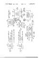
- FIG. 1is a diagrammatic illustration of the various functional components which together form an entire audio and video television coding system
- FIG. 2is a block diagram of the input video processor
- FIG. 3is a block diagram of the input audio processor
- FIG. 4is a block diagram of the audio and reference data processor
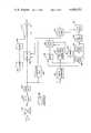
- FIG. 5is a block diagram of the scene change detector
- FIG. 6is a block diagram of the scrambling enhancement assembly
- FIG. 7is a block diagram of the output video processor.
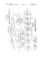
- FIG. 8is a block diagram of the decoder.
- FIG. 9is a waveform diagram of the standard NTSC video signal illustrating the horizontal sync pulse, the color burst and the color bars.
- FIG. 10is a waveform diagram, similar to FIG. 9, but illustrating the replacement of horizontal sync with digitized audio, and a bias applied to the color burst,
- FIG. 11is a waveform diagram illustrating the scrambled video signal of FIG. 10 with video polarity reversed, except for the color burst,
- FIG. 12is a waveform diagram illustrating the instantaneous effect of amplitude modulation applied to the three data bytes.
- FIG. 13is a diagrammatic illustration of the application of a low frequency sine wave to a video signal frame.
- the present inventionrelates to subscription television and in particular to a means for scrambling or encoding or distorting both the video and audio portions of a television signal so that the program has no entertainment value unless the subscriber has the proper decoding equipment.
- the primary means for encodingis the suppression of all synchronizing information in both the vertical and horizontal blanking intervals as described in co-pending application Ser. No. 965,940 assigned to the assignee of the present application.
- the sound or audio informationis placed in digital form and is inserted in the horizontal blanking interval in place of the normal horizontal sync information.
- the videomay be inverted and this inversion may take place on the basis of program scene changes.
- the videomay be distorted by both shifting the voltage level of the digital information in the horizontal interval, as well as by varying the voltage level of this portion of a horizontal line by the application of a sine wave phased to vary the amplitude of the horizontal blanking portion of each line.
- amplitude modulationis applied to the aural carrier in such a way that chrominance subcarrier video information will not provide synchronization.
- FIG. 1diagrammatically illustrates the encoding equipment and FIG. 8 diagrammatically illustrates the decoder.
- the input video processoris indicated at 10 and has an input of base band video (FIG. 9) and outputs of the following signals: a filtered video signal, a 4.0909 MHz clock, a frame reference pulse, a color burst gate signal, and a clamped video output.
- base band videoFIG. 9
- a filtered video signala 4.0909 MHz clock
- a frame reference pulsea color burst gate signal
- clamped video outputThe use of these various signals will be described in connection with the remaining portions of the circuit.
- An input audio processor 12receives the input audio signal and provides an output of the audio information in digital form.
- the audio information in digital formis connected to an audio and reference data processor 14 whose output will be data to enable the subscriber decoders as well as the audio information in digital form.
- the output from processor 14is directed to output video processor 16 wherein this data is combined with the video signal for subsequent transmission on a suitable carrier.
- a horizontal timing generator 18 and a vertical timing generator 20provide various timing signals which coordinate the audio and video processors as well as the operation of a scrambling enhancement assembly 22.
- a scene change detector 24has an input of filtered video and an output designed to control inversion of the video in output video processor 16 in accordance with program scene changes.
- Attenuator 28which permits manual adjustment of the video gain in order to accomodate operating conditions of different video sources. Attenuator 28 is connected to an amplifier 30 which functions as an isolation stage between the video source and the following video processing circuit, as well as providing a small gain (2X) to allow for low amplitude video signals.
- a clamp 32is connected to amplifier 30 and clamps the video signal at a specific level as is common in television operations.
- the output from clamp 32is the video signal clamped at an appropriate level which output is passed directly to the output video processor 16 which will be described in detail hereinafter.
- a filter 34is also connected to amplifier 30 and is a low pass filter effectively removing all color signals that may interfere with the various following sync separation circuits.
- the output from filter 34is thus a low bandwidth monochrome video signal which will be used in scene change detector 24.
- the output from filter 34is also connected to a second amplifier 36 whose output in turn is connected to a sync separating circuit 38.
- sync separating circuit 38One output from sync separating circuit 38 is to a clock circuit 40 which provides a 4.0909 MHz clock signal synchronized with the frequency of the horizontal sync pulses of the incoming video.
- a pulse processing circuit 42is also connected to sync separator 38 and provides two outputs. The first, a frame reference signal, is a pulse coincident with the leading edge of the first serration pulse of the vertical interval immediately preceding the odd field. This pulse is required for synchronization of the internal timing signals with the input video.
- a second output from pulse processor 42is a color burst gate signal which is coincident with the color burst of each line of the incoming video. The color burst gate will be suppressed during the vertical sync period when no color burst is being received.
- the horizontal timing generator 18will have an input of the clock and frame reference signals from video processor 10.
- the timing generatorwill provide a number of signals all synchronized by its two inputs. Each horizontal line is divided into 260 parts of approximately 250 NS each.
- the following tableindicates the position of the various timing pulses in a horizontal line. In addition to the pulses of the table, the timing generator will provide an approximate 500 KHz and a two MHz signal for operation of certain of the circuits, as described.
- Vertical timing generator 20will provide four outputs, the first being the field index signal which will be a very short duration pulse at approximately the middle of the fifth line of the vertical interval (FI); a vertical drive signal, a positive pulse beginning at the first line of the vertical interval and extending to the ninth line of that interval (VD); a vertical blanking signal which is a positive pulse beginning with the initiation of the vertical interval and extending until line 21 of the vertical interval (VB); and a vertical window signal which is a positive pulse beginning at line 46 and extending until line 238 (VW).
- the firstbeing the field index signal which will be a very short duration pulse at approximately the middle of the fifth line of the vertical interval (FI); a vertical drive signal, a positive pulse beginning at the first line of the vertical interval and extending to the ninth line of that interval (VD); a vertical blanking signal which is a positive pulse beginning with the initiation of the vertical interval and extending until line 21 of the vertical interval (VB); and a vertical window signal which is a positive pulse beginning at line 46 and extending
- FIG. 3illustrates the input audio processor circuit.
- the audio signalis directed to an attenuator 44 which functions in a manner similar to attenuator 28 and the output of the attenuator is connected to a low pass filter 46 which limits the pass band to approximately 12 KHz, the audible range. Higher frequency signals would cause distortion in the subsequent digitizing process.
- a sample and hold circuit 48is connected to filter 46 and is gated by the sound sample gate signals from horizontal timing generator 18. Circuit 48 will sample the sound during the period that it is gated and will hold the amplitude level of the sound until the next sound sample. As indicated in the previous table, the first audio sample will be made approximately 3.5 microseconds after the start of the horizontal line, with the second audio sample being made approximately 35 microseconds after the beginning of the horizontal line.
- the sound sampleswill be converted to digital form by an analog to digital converter 50 which is clocked by a 500 KHz signal from horizontal timing generator 18. Alternate outputs from ADC 50 are connected, in parallel form, to storage registers 52 and 54. The data from the storage registers will be transferred to audio and reference data processor circuit 14 in accordance with the operation of a flip-flop 56. Flip-flop 56 will be gated by the sound sample and horizontal drive (HD) outputs from horizontal timing generator 18. For example, each of the sound samples may be an eight-bit digital word and the samples may be taken at a rate of approximately 31,500 per second.
- HDsound sample and horizontal drive
- a storage register 58has three sections, one for sound byte 1 (the first sound sample), indicated at 60, a second for sound byte 2 (the second sound sample), indicated at 62, and a third for a digital receiver clock sync pattern, indicated at 64.
- the sync patternwill be hard-wired into the storage register and will in binary form provide the clock signal for the decoder.
- the parallel information in storage register 58will be moved, again in a parallel manner, to a shift register 66 upon being gated by the shift register load pulse from horizontal timing generator 18.
- a second input for shift register 66is provided by storage register 68 which has a hard-wired vertical drive reference pattern, which code sequence, again in binary form, is used by the decoder to recognize the existence of an encoded video signal and to reset the decoder time sequence.
- the field index signal from vertical timing generator 20is used to move the reference pattern from storage register 68, once each frame, into shift register 66.
- the data in shift register 66will be gated to the output video processor in accordance with the presence of either field index or shift register load signals at the input of an OR gate 70 which is connected to shift register 66. The information will be shifted out in accordance with the input four MHz clock signal.
- FIG. 10illustrates the three-byte data insertion into the horizontal blanking interval in place of the horizontal sync pulse illustrated in FIG. 9.
- the scene change detector(FIG. 5) has an input of low bandwidth monochrome video from the input video processor and this signal is connected to a voltage comparator 72.
- Analog comparator 72compares the instantaneous brightness of the video signal with the average brightness over a period of time, for example three frames.
- the output from comparator 72is sampled at a rate of 2,048 samples per field and these samples are stored in shift register 74.
- the binary video at the output of comparator 72is sampled at a rate of 32 samples in one out of every three lines over a period of 192 lines in each field.
- a divide by three circuit 76is clocked by the horizontal drive and reset by the vertical window.
- the vertical windowin addition to resetting the divide by three circuit, thus insuring the same starting point in every frame, also prevents counting and blocks the output of this circuit during the vertical interval.
- divide by three circuit 76produces a pulse during every third line except during the vertical interval.
- a divide by six circuit 78is driven by the 4 MHz clock and reset by divide by three circuit 76 and the horizontal window. Accordingly, the divide by six circuit 78 produces output pulses only every line and only during the horizontal window. Since the horizontal window lasts for 192 clock pulses and divide by six circuit 78 produces one output pulse for every six clock pulses, there are 32 sample pulses every third line except during the vertical interval.
- a digital comparator 80is connected to the output of shift register 74 and compares the output binary number from shift register 74 with the output binary number from comparator 72. Thus, the brightness level of one field is compared with the brightness level of the preceding field at each of the same locations in the field.
- the output from digital comparator 80which will be either high or low, depending upon whether the brightness levels are the same or different, is connected to a clocked counter 82.
- Counter 82receives the output from divide circuits 76 and 78 and thus is clocked at the same rate as shift register 74. Clocked counter 82 will count pulses at the described sample rate when the comparator output from circuit 80 is high indicating dissimilar inputs.
- clocked counter 82whenever there is a difference in the brightness levels from one field to the next, that indication of a brighness change will be registered by clocked counter 82.
- the counteris reset by the vertical drive signal so that a new count begins for each field.
- Clocked counter 82is connected to a digital comparator 84 which has a preset number, as provided by a series of manual switches diagrammatically indicated at 86.
- the threshold for recognition of a scene changecan be varied.
- the number from clocked counter 82when it exceeds the number provided by preset switches 86 is indicative of a scene change as there have been a sufficient number of changes in the brightness level from one field to the next to indicate a scene change.
- the output from digital comparator 84is a pulse indicating that in fact a scene change has taken place and this pulse is connected to a time delay 88.
- Time delay 88may typically have a three second period and thus will not register a new scene change unless three seconds have elapsed. In this way, fast moving objects or the like will not trigger a polarity change.
- Time delay circuit 88is connected to a field sync circuit 90 which is gated by the vertical drive signal from vertical timing generator 20.
- a scene changewhich will cause inversion or a change of polarity of the video signal as described, will only take place at the end of a field and such inversion will not take place at a greater frequency than every three seconds.
- the scene change detector output of field sync 90is connected to output video processor 16.
- FIG. 6illustrates certain circuits which can be utilized to further enhance the scrambling of the video signal.
- a data swing oscillator 92is a free running generator oscillating at a frequency of for example approximately 15 Hz. This variable signal will be applied to the data to vary the level thereof at the output of video processor 16.
- the second circuit in scrambling enhancement assembly 22is an aural amplitude modulating oscillator 94 which provides a frequency of approximately 15.75 KHz, which frequency will be varied approximately 15-30 Hz on either side of the base frequency. Such a swept frequency will be applied to the aural carrier at the transmitter.
- a third signal in scrambling enhancement assembly 22is provided by a random data modulator 96.
- This circuithas inputs of horizontal drive, vertical drive, and the four MHz clock.
- Modulator 96has three outputs, only one of which will be high during each horizontal drive period. The pattern as to which of the three outputs will be high will only be repeated after approximately 65,000 patterns.
- the horizontal drive pulsegates the circuit into operation and the vertical drive pulse will advance the sequence one step. The sequence is continually changing at the vertical drive rate of 60 Hz.
- FIG. 7illustrates the output video processor.
- An inverteris indicated at 98 and receives one input from scene change detector 24 and a second input of the standard clamped video from input video processor 10. Inverter 98 will either reverse the polarity of the video signal or not depending upon the output from scene change detector 24.
- the scrambled non-inverted video signalis illustrated in FIG. 10 and the scrambled inverted video signal is illustrated in FIG. 11.
- the video signal as applied to inverter 98is also applied to a switch 100 which will normally block the video signal except during the period of the color burst as controlled by the color burst gate signal applied from input video processor 10. Thus, the output from switch 100 will be the video color burst.
- a burst bias circuit 102has inputs of vertical drive, horizontal drive and the color burst gate.
- the burst bias circuitwhen gated by the color burst gate and not inhibited by either the vertical drive or horizontal drive signals, will provide a DC level or bias voltage for the color burst but will not bias the data.
- Burst bias circuit 102is connected to the output of switch 100 so as to provide the bias for the color burst signal. Compare the bias of the color burst signal in the unscrambled waveform of FIG. 9 and the scrambled waveform of FIG. 10.
- the data information from audio and reference data processor 14provides one input to an amplifier 104 whose gain is controlled by the three outputs from random data modulator 96.
- which of the three data bytes will have an enhanced amplitudeis determined by which output is high from modulator 96.
- FIG. 12illustrates one of the three data bytes with an enhanced amplitude.
- the output from amplifier 104is connected to a swing circuit 106 which receives the output from data swing oscillator 92.
- the three data bytes, in addition to having one of the three enhanced in amplitude,will in total have their bias level varied in accordance with the 15 Hz signal from oscillator 92.
- FIG. 13diagrammatically illustrates the effect of the 15 Hz signal on a single frame of the video signal.
- the output from swing circuit 106is connected to switch 108 as are the outputs from switch 100 and burst bias 102.
- Switch 108normally passes the video signal from inverter 98. However, during the horizontal blanking interval, as determined by the horizontal blanking gate applied to the switch, the switch will pass the inputs from swing circuit 106, burst bias 102 and switch 100. Thus, in the horizontal blanking interval, the output from the switch will be the three data bytes enhanced as described and the color burst, all at a predetermined bias level.
- the output from switch 108is connected to an amplifier 110, with the output from the amplifier going to the transmitter.
- the output from amplifier 110is a video signal with all horizontal and vertical sync information removed, which video signal will be polarity inverted or not, depending upon changes in scene of the actual picture.
- the horizontal blanking intervalwill be filled with sound data bytes and the conventional color burst as well as the receiver clock sync pattern which is used to control the clock of each decoder.
- the vertical drive reference patternwill be inserted, which enables the decoders to recognize the existence of an encoded video signal.
- the data in the blanking intervalwill vary, as described, as effected by the data swing oscillator and the random data modulator.
- the decoderis illustrated in FIG. 8.
- subscription programswill be carried on either a UHF or VHF station and such programs will only be broadcast during a portion of the station's overall air time.
- the input for the decoderis a UHF or VHF tuner 120 which provides an output IF signal, for example at frequencies of 41.25 MHz and 45.75 MHz, respectively.
- the program audiois coded, the audio carrier may in fact be used for other purposes, such as additional sound, or as a barker channel.
- the output from tuner 120is connected to an IF amplifier 122 whose output is connected to a video detector 124 which provides base band video and a 4.5 MHz audio carrier.
- the video informationwill pass through a switch 126 directly to a modulator 128 which will provide an output usable in a TV receiver.
- the audio signalwill pass through a filter 129 and an amplifier 130 whose output is also connected to modulator 128.
- the entire program of both audio and videowill pass in the conventional manner.
- the decoderwill have no effect upon either signal.
- the output from video detector 124is connected to a data separator 132 which provides an output with three different types of information.
- the data separatorprovides a signal which allows the vertical reference pattern detector 134 to recognize the existence of coded video and provides a reset pulse for sync generator 136.
- Sync generator 136will provide the complete series of horizontal and vertical sync pulses necessary to properly control the video information so that it may be recognizably displayed on a TV receiver. There will be a horizontal drive signal, a vertical drive signal, a composite sync signal and a composite blanking signal.
- Sync generator 136is controlled by a clock 138 which is synchronized by the sync pattern which has been transmitted as one of the three data bytes in the horizontal blanking interval. This clock signal will properly regulate the operation of the sync generator as gated by the vertical pattern recognition circuit.
- the third output from data separator 132is the audio information in the form of the two data bytes.
- This informationis passed to a first shift register 140 and a second shift register 142 whose outputs are both connected to a digital-to-analog converter 144 whose output is the audio information in analog or conventional audio form.
- the operation of the shift registersare controlled by clock 138 and by a timer 146 which is gated by the horizontal drive output from sync generator 136.
- the timerprovides an internally generated clock which consists of two 15.734 KHz signals of opposite phase which alternates operation of the shift registers and is gated or controlled as described by the horizontal drive signal.
- the datagoes into the two shift registers in serial form and comes out in a parallel manner where it is converted by the digital-to-analog converter into conventional audio information.
- the output from digital-to-analog converter 144goes to an FM modulator 145 which will provide the conventional FM signal normally associated with a television program.
- the output from FM modulator 145is connected to modulator 128 and to a frequency comparison circuit 147.
- the basis for frequency comparisonis the horizontal drive signal which will be at a very specific 15.734 KHz. This is compared with the FM carrier of 4.5 MHz divided by 286 and any difference is used to control the FM modulator so that it stays precisely on frequency.
- An inversion detector 148is also connected to the output of video detector 124 and the presence of an inverted video signal may, for example, be determined by the level of line 23 in the vertical blanking interval.
- the manner in which a video inversion control signal is transmitted to a receivermay vary. Such a signal may occupy a portion of a horizontal line in the vertical interval or it may be transmitted with address information in the manner shown in U.S. Pat. Nos. 4,145,717 and 4,112,464.
- the output from inversion detector 148is connected directly to modulator 128 where it is effective to cause inversion of the video signal in accordance with inversions of that signal at the transmitter.
- Switch 126receives all of the necessary sync information from sync generator 136. This switch will pass the video signal except as it is gated during the horizontal and vertical blanking intervals to pass only the sync information from sync generator 136. Thus, the output from switch 126 will be the video signal as transmitted with the proper synchronization information inserted therein, which output will subsequently either be inverted or not, depending upon the condition of inversion detector 148. In the case of a signal inversion, the sync will also have to be inverted, which function is also performed by switch 126.
- the video signalhas been reconstituted by the addition of the sync information deleted at the transmitter.
- the video signalis inverted or not in accordance with the output of the inversion detector.
- the audio informationis detected, converted to an analog form and placed on a controlled FM carrier.
- the decoder or data separatorignores the varying level of the three data bytes, as brought about by the data swing generator and similarly ignores any enhancement of one of the three data bytes as controlled by the random data modulator. This is brought about by appropriate bias control in the data separator.
- a receiver without an appropriate decodercannot ignore such variations in signal level during the horizontal blanking intervals and, as described, will be unable to sync on any repetitive signal.
- the vertical reference pattern recognition circuitis arranged to recognize the binary reference pattern as provided by storage register 68 in the audio and reference data processor. As indicated above, such recognition effectively permits the decoder to operate in the manner described.
Landscapes
- Engineering & Computer Science (AREA)
- Multimedia (AREA)
- Signal Processing (AREA)
- Television Systems (AREA)
Abstract
Description
______________________________________ Timing pulse Start Stop ______________________________________ SRLShift register load 3 4 SS1 First audio sample 14 33 SS2Second audio sample 144 163 HD Horizontal drive 9 36 HB Horizontal blanking 9 59 HWHorizontal window 60 252 ______________________________________
Claims (5)
Priority Applications (1)
| Application Number | Priority Date | Filing Date | Title |
|---|---|---|---|
| US06/492,706US4424532A (en) | 1980-05-14 | 1983-05-09 | Coding and decoding system for video and audio signals |
Applications Claiming Priority (2)
| Application Number | Priority Date | Filing Date | Title |
|---|---|---|---|
| US06/149,707US4353088A (en) | 1980-05-14 | 1980-05-14 | Coding and decoding system for video and audio signals |
| US06/492,706US4424532A (en) | 1980-05-14 | 1983-05-09 | Coding and decoding system for video and audio signals |
Related Parent Applications (2)
| Application Number | Title | Priority Date | Filing Date |
|---|---|---|---|
| US96594078AContinuation-In-Part | 1978-12-04 | 1978-12-04 | |
| US06368854Continuation | 1982-04-15 |
Publications (1)
| Publication Number | Publication Date |
|---|---|
| US4424532Atrue US4424532A (en) | 1984-01-03 |
Family
ID=26846964
Family Applications (1)
| Application Number | Title | Priority Date | Filing Date |
|---|---|---|---|
| US06/492,706Expired - LifetimeUS4424532A (en) | 1980-05-14 | 1983-05-09 | Coding and decoding system for video and audio signals |
Country Status (1)
| Country | Link |
|---|---|
| US (1) | US4424532A (en) |
Cited By (28)
| Publication number | Priority date | Publication date | Assignee | Title |
|---|---|---|---|---|
| US4608456A (en)* | 1983-05-27 | 1986-08-26 | M/A-Com Linkabit, Inc. | Digital audio scrambling system with error conditioning |
| US4618888A (en)* | 1983-02-18 | 1986-10-21 | Sanyo Electric Co., Ltd. | Scrambling system of television signal |
| US4636854A (en)* | 1983-06-20 | 1987-01-13 | U.S. Philips Corporation | Transmission system |
| US4651205A (en)* | 1983-06-20 | 1987-03-17 | U.S. Philips Corporation | Television transmission system |
| US4682360A (en)* | 1983-12-22 | 1987-07-21 | Frederiksen Jeffrey E | Video transmission system |
| EP0152309A3 (en)* | 1984-02-15 | 1987-08-05 | Matsushita Electric Industrial Co., Ltd. | Television sound signal processing apparatus |
| US4688246A (en)* | 1985-12-20 | 1987-08-18 | Zenith Electronics Corporation | CATV scrambling system with compressed digital audio in synchronizing signal intervals |
| US4697277A (en)* | 1985-02-21 | 1987-09-29 | Scientific Atlanta, Inc. | Synchronization recovery in a communications system |
| US4727579A (en)* | 1983-05-13 | 1988-02-23 | U.S. Philips Corporation | Scrambled television signals |
| US4739510A (en)* | 1985-05-01 | 1988-04-19 | General Instrument Corp. | Direct broadcast satellite signal transmission system |
| US4815129A (en)* | 1985-01-02 | 1989-03-21 | General Instrument Corp. | Video encryption system |
| US4817142A (en)* | 1985-05-21 | 1989-03-28 | Scientific Atlanta, Inc. | Restoring framing in a communications system |
| US4908834A (en)* | 1984-10-12 | 1990-03-13 | Wiedemer John D | High security pay television system |
| US5103477A (en)* | 1990-03-16 | 1992-04-07 | Pioneer Electronic Corporation | Method and apparatus for descrambling a television signal |
| US5153723A (en)* | 1991-07-24 | 1992-10-06 | Zenith Electronics Corporation | HDTV audio subsystem with timing characteristics compatible with video subsystem |
| US5191609A (en)* | 1990-04-14 | 1993-03-02 | Samsung Electronics Co., Ltd. | Scrambling and unscrambling circuit |
| US5335277A (en) | 1981-11-03 | 1994-08-02 | The Personalized Mass Media Corporation | Signal processing appparatus and methods |
| WO1994017622A3 (en)* | 1993-01-15 | 1994-09-15 | Elektronika Ltd N Proizv | Method of relaying data via television channels and a system for carrying out same |
| EP0635977A1 (en)* | 1990-01-19 | 1995-01-25 | British Broadcasting Corporation | High definition television coder/decoder synchronisation |
| US5519433A (en)* | 1991-11-20 | 1996-05-21 | Zing Systems, L.P. | Interactive television security through transaction time stamping |
| WO1996037076A1 (en)* | 1995-05-19 | 1996-11-21 | Pires H George | Video scrambling with variable function generator |
| US5640210A (en)* | 1990-01-19 | 1997-06-17 | British Broadcasting Corporation | High definition television coder/decoder which divides an HDTV signal into stripes for individual processing |
| US5710815A (en)* | 1995-06-07 | 1998-01-20 | Vtech Communications, Ltd. | Encoder apparatus and decoder apparatus for a television signal having embedded viewer access control data |
| US5768377A (en)* | 1995-10-25 | 1998-06-16 | Samsung Electro-Mechanics Co., Ltd. | Video signal descrambling apparatus |
| US6064440A (en)* | 1998-01-08 | 2000-05-16 | Navis Digital Media Systems | Apparatus for inserting data into the vertical blanking interval of a video signal |
| US20070252893A1 (en)* | 2005-06-14 | 2007-11-01 | Toshiaki Shigemori | Receiving Apparatus, Transmitting Apparatus And In-Vivo Information Acquiring Apparatus |
| US7769344B1 (en) | 1981-11-03 | 2010-08-03 | Personalized Media Communications, Llc | Signal processing apparatus and methods |
| USRE47642E1 (en) | 1981-11-03 | 2019-10-08 | Personalized Media Communications LLC | Signal processing apparatus and methods |
Citations (9)
| Publication number | Priority date | Publication date | Assignee | Title |
|---|---|---|---|---|
| US2510046A (en) | 1947-04-18 | 1950-05-30 | Zenith Radio Corp | Radio-wire signaling system |
| US2705740A (en) | 1949-12-14 | 1955-04-05 | Zenith Radio Corp | Subscription type signalling system |
| US3081376A (en) | 1959-03-23 | 1963-03-12 | Zenith Radio Corp | Subscription television system |
| US3313880A (en) | 1962-08-30 | 1967-04-11 | R & R Res Ltd | Secrecy television system with false synchronizing signals |
| US3485941A (en) | 1965-04-12 | 1969-12-23 | R & R Research Ltd | Television system with modified sync signals and auxiliary timing information |
| US3530232A (en) | 1966-06-17 | 1970-09-22 | Intern Telemeter Corp | Subscription television system |
| US4081832A (en) | 1976-06-08 | 1978-03-28 | Pay Television Corporation | Pay television system, method and apparatus |
| US4095258A (en) | 1976-10-15 | 1978-06-13 | Blonder-Tongue Laboratories, Inc. | Apparatus for decoding scrambled television and similar transmissions |
| US4215366A (en) | 1977-10-19 | 1980-07-29 | Feature Film Services | Subscriber-limited reception television broadcast security encoder-decoder system |
- 1983
- 1983-05-09USUS06/492,706patent/US4424532A/ennot_activeExpired - Lifetime
Patent Citations (9)
| Publication number | Priority date | Publication date | Assignee | Title |
|---|---|---|---|---|
| US2510046A (en) | 1947-04-18 | 1950-05-30 | Zenith Radio Corp | Radio-wire signaling system |
| US2705740A (en) | 1949-12-14 | 1955-04-05 | Zenith Radio Corp | Subscription type signalling system |
| US3081376A (en) | 1959-03-23 | 1963-03-12 | Zenith Radio Corp | Subscription television system |
| US3313880A (en) | 1962-08-30 | 1967-04-11 | R & R Res Ltd | Secrecy television system with false synchronizing signals |
| US3485941A (en) | 1965-04-12 | 1969-12-23 | R & R Research Ltd | Television system with modified sync signals and auxiliary timing information |
| US3530232A (en) | 1966-06-17 | 1970-09-22 | Intern Telemeter Corp | Subscription television system |
| US4081832A (en) | 1976-06-08 | 1978-03-28 | Pay Television Corporation | Pay television system, method and apparatus |
| US4095258A (en) | 1976-10-15 | 1978-06-13 | Blonder-Tongue Laboratories, Inc. | Apparatus for decoding scrambled television and similar transmissions |
| US4215366A (en) | 1977-10-19 | 1980-07-29 | Feature Film Services | Subscriber-limited reception television broadcast security encoder-decoder system |
Cited By (135)
| Publication number | Priority date | Publication date | Assignee | Title |
|---|---|---|---|---|
| US9043859B1 (en) | 1981-11-02 | 2015-05-26 | Personalized Media Communications, Llc | Signal processing apparatus and methods |
| US7856650B1 (en) | 1981-11-03 | 2010-12-21 | Personalized Media Communications, Llc | Signal processing apparatus and methods |
| US7860131B1 (en) | 1981-11-03 | 2010-12-28 | Personalized Media Communications, Llc | Signal processing apparatus and methods |
| US7860249B1 (en) | 1981-11-03 | 2010-12-28 | Personalized Media Communications LLC | Signal processing apparatus and methods |
| USRE48633E1 (en) | 1981-11-03 | 2021-07-06 | Personalized Media Communications LLC | Reprogramming of a programmable device of a specific version |
| USRE48565E1 (en) | 1981-11-03 | 2021-05-18 | Personalized Media Communications LLC | Providing a subscriber specific solution in a computer network |
| USRE48484E1 (en) | 1981-11-03 | 2021-03-23 | Personalized Media Communications, Llc | Signal processing apparatus and methods |
| US10715835B1 (en) | 1981-11-03 | 2020-07-14 | John Christopher Harvey | Signal processing apparatus and methods |
| USRE47968E1 (en) | 1981-11-03 | 2020-04-28 | Personalized Media Communications LLC | Signal processing apparatus and methods |
| US10616638B1 (en) | 1981-11-03 | 2020-04-07 | Personalized Media Communications LLC | Signal processing apparatus and methods |
| US10609425B1 (en) | 1981-11-03 | 2020-03-31 | Personalized Media Communications, L.L.C. | Signal processing apparatus and methods |
| USRE47867E1 (en) | 1981-11-03 | 2020-02-18 | Personalized Media Communications LLC | Signal processing apparatus and methods |
| US10523350B1 (en) | 1981-11-03 | 2019-12-31 | Personalized Media Communications LLC | Signal processing apparatus and methods |
| USRE47642E1 (en) | 1981-11-03 | 2019-10-08 | Personalized Media Communications LLC | Signal processing apparatus and methods |
| US10334292B1 (en) | 1981-11-03 | 2019-06-25 | Personalized Media Communications LLC | Signal processing apparatus and methods |
| US9674560B1 (en) | 1981-11-03 | 2017-06-06 | Personalized Media Communications LLC | Signal processing apparatus and methods |
| US5335277A (en) | 1981-11-03 | 1994-08-02 | The Personalized Mass Media Corporation | Signal processing appparatus and methods |
| US9294205B1 (en) | 1981-11-03 | 2016-03-22 | Personalized Media Communications LLC | Signal processing apparatus and methods |
| US9210370B1 (en) | 1981-11-03 | 2015-12-08 | Personalized Media Communications LLC | Signal processing apparatus and methods |
| US9038124B1 (en) | 1981-11-03 | 2015-05-19 | Personalized Media Communications, Llc | Signal processing apparatus and methods |
| US8973034B1 (en) | 1981-11-03 | 2015-03-03 | Personalized Media Communications LLC | Signal processing apparatus and methods |
| US8914825B1 (en) | 1981-11-03 | 2014-12-16 | Personalized Media Communications LLC | Signal processing apparatus and methods |
| US8893177B1 (en) | 1981-11-03 | 2014-11-18 | {Personalized Media Communications, LLC | Signal processing apparatus and methods |
| US8869229B1 (en) | 1981-11-03 | 2014-10-21 | Personalized Media Communications, Llc | Signal processing apparatus and methods |
| US8869228B1 (en) | 1981-11-03 | 2014-10-21 | Personalized Media Communications, Llc | Signal processing apparatus and methods |
| US8843988B1 (en) | 1981-11-03 | 2014-09-23 | Personalized Media Communications, Llc | Signal processing apparatus and methods |
| US8839293B1 (en) | 1981-11-03 | 2014-09-16 | Personalized Media Communications, Llc | Signal processing apparatus and methods |
| US8804727B1 (en) | 1981-11-03 | 2014-08-12 | Personalized Media Communications, Llc | Signal processing apparatus and methods |
| US5887243A (en) | 1981-11-03 | 1999-03-23 | Personalized Media Communications, L.L.C. | Signal processing apparatus and methods |
| US8752088B1 (en) | 1981-11-03 | 2014-06-10 | Personalized Media Communications LLC | Signal processing apparatus and methods |
| US8739241B1 (en) | 1981-11-03 | 2014-05-27 | Personalized Media Communications LLC | Signal processing apparatus and methods |
| US7734251B1 (en) | 1981-11-03 | 2010-06-08 | Personalized Media Communications, Llc | Signal processing apparatus and methods |
| US7747217B1 (en) | 1981-11-03 | 2010-06-29 | Personalized Media Communications, Llc | Signal processing apparatus and methods |
| US7752649B1 (en) | 1981-11-03 | 2010-07-06 | Personalized Media Communications, Llc | Signal processing apparatus and methods |
| US7752650B1 (en) | 1981-11-03 | 2010-07-06 | Personalized Media Communications, Llc | Signal processing apparatus and methods |
| US7761890B1 (en) | 1981-11-03 | 2010-07-20 | Personalized Media Communications, Llc | Signal processing apparatus and methods |
| US7764685B1 (en) | 1981-11-03 | 2010-07-27 | Personalized Media Communications, L.L.C. | Signal processing apparatus and methods |
| US7769170B1 (en) | 1981-11-03 | 2010-08-03 | Personalized Media Communications, Llc | Signal processing apparatus and methods |
| US7769344B1 (en) | 1981-11-03 | 2010-08-03 | Personalized Media Communications, Llc | Signal processing apparatus and methods |
| US7774809B1 (en) | 1981-11-03 | 2010-08-10 | Personalized Media Communications, Llc | Signal processing apparatus and method |
| US7783252B1 (en) | 1981-11-03 | 2010-08-24 | Personalized Media Communications, Llc | Signal processing apparatus and methods |
| US7784082B1 (en) | 1981-11-03 | 2010-08-24 | Personalized Media Communications, Llc | Signal processing apparatus and methods |
| US7793332B1 (en) | 1981-11-03 | 2010-09-07 | Personalized Media Communications, Llc | Signal processing apparatus and methods |
| US7797717B1 (en) | 1981-11-03 | 2010-09-14 | Personalized Media Communications, Llc | Signal processing apparatus and methods |
| US7801304B1 (en) | 1981-11-03 | 2010-09-21 | Personalized Media Communications, Llc | Signal processing apparatus and methods |
| US7805738B1 (en) | 1981-11-03 | 2010-09-28 | Personalized Media Communications, Llc | Signal processing apparatus and methods |
| US7805748B1 (en) | 1981-11-03 | 2010-09-28 | Personalized Media Communications, Llc | Signal processing apparatus and methods |
| US7805749B1 (en) | 1981-11-03 | 2010-09-28 | Personalized Media Communications, Llc | Signal processing apparatus and methods |
| US7810115B1 (en) | 1981-11-03 | 2010-10-05 | Personalized Media Communications, Llc | Signal processing apparatus and methods |
| US7814526B1 (en) | 1981-11-03 | 2010-10-12 | Personalized Media Communications, Llc | Signal processing apparatus and methods |
| US7818776B1 (en) | 1981-11-03 | 2010-10-19 | Personalized Media Communications, Llc | Signal processing apparatus and methods |
| US7817208B1 (en) | 1981-11-03 | 2010-10-19 | Personalized Media Communications, Llc | Signal processing apparatus and methods |
| US7818778B1 (en) | 1981-11-03 | 2010-10-19 | Personalized Media Communications, Llc | Signal processing apparatus and methods |
| US7818761B1 (en) | 1981-11-03 | 2010-10-19 | Personalized Media Communications, Llc | Signal processing apparatus and methods |
| US7818777B1 (en) | 1981-11-03 | 2010-10-19 | Personalized Media Communications, Llc | Signal processing apparatus and methods |
| US7823175B1 (en) | 1981-11-03 | 2010-10-26 | Personalized Media Communications LLC | Signal processing apparatus and methods |
| US7827586B1 (en) | 1981-11-03 | 2010-11-02 | Personalized Media Communications, Llc | Signal processing apparatus and methods |
| US7827587B1 (en) | 1981-11-03 | 2010-11-02 | Personalized Media Communications, Llc | Signal processing apparatus and methods |
| US7831204B1 (en) | 1981-11-03 | 2010-11-09 | Personalized Media Communications, Llc | Signal processing apparatus and methods |
| US7830925B1 (en) | 1981-11-03 | 2010-11-09 | Personalized Media Communications, Llc | Signal processing apparatus and methods |
| US7836480B1 (en) | 1981-11-03 | 2010-11-16 | Personalized Media Communications, Llc | Signal processing apparatus and methods |
| US7840976B1 (en) | 1981-11-03 | 2010-11-23 | Personalized Media Communications, Llc | Signal processing apparatus and methods |
| US7844995B1 (en) | 1981-11-03 | 2010-11-30 | Personalized Media Communications, Llc | Signal processing apparatus and methods |
| US7849493B1 (en) | 1981-11-03 | 2010-12-07 | Personalized Media Communications, Llc | Signal processing apparatus and methods |
| US7849479B1 (en) | 1981-11-03 | 2010-12-07 | Personalized Media Communications, Llc | Signal processing apparatus and methods |
| US7856649B1 (en) | 1981-11-03 | 2010-12-21 | Personalized Media Communications, Llc | Signal processing apparatus and methods |
| US8713624B1 (en) | 1981-11-03 | 2014-04-29 | Personalized Media Communications LLC | Signal processing apparatus and methods |
| US7849480B1 (en) | 1981-11-03 | 2010-12-07 | Personalized Media Communications LLC | Signal processing apparatus and methods |
| US8711885B1 (en) | 1981-11-03 | 2014-04-29 | Personalized Media Communications LLC | Signal processing apparatus and methods |
| USRE48682E1 (en) | 1981-11-03 | 2021-08-10 | Personalized Media Communications LLC | Providing subscriber specific content in a network |
| US7861278B1 (en) | 1981-11-03 | 2010-12-28 | Personalized Media Communications, Llc | Signal processing apparatus and methods |
| US7861263B1 (en) | 1981-11-03 | 2010-12-28 | Personalized Media Communications, Llc | Signal processing apparatus and methods |
| US7864956B1 (en) | 1981-11-03 | 2011-01-04 | Personalized Media Communications, Llc | Signal processing apparatus and methods |
| US7865920B1 (en) | 1981-11-03 | 2011-01-04 | Personalized Media Communications LLC | Signal processing apparatus and methods |
| US7864248B1 (en) | 1981-11-03 | 2011-01-04 | Personalized Media Communications, Llc | Signal processing apparatus and methods |
| US7870581B1 (en) | 1981-11-03 | 2011-01-11 | Personalized Media Communications, Llc | Signal processing apparatus and methods |
| US7889865B1 (en) | 1981-11-03 | 2011-02-15 | Personalized Media Communications, L.L.C. | Signal processing apparatus and methods |
| US7908638B1 (en) | 1981-11-03 | 2011-03-15 | Personalized Media Communications LLC | Signal processing apparatus and methods |
| US7926084B1 (en) | 1981-11-03 | 2011-04-12 | Personalized Media Communications LLC | Signal processing apparatus and methods |
| US7940931B1 (en) | 1981-11-03 | 2011-05-10 | Personalized Media Communications LLC | Signal processing apparatus and methods |
| US7953223B1 (en) | 1981-11-03 | 2011-05-31 | Personalized Media Communications, L.L.C. | Signal processing apparatus and methods |
| US8683539B1 (en) | 1981-11-03 | 2014-03-25 | Personalized Media Communications, Llc | Signal processing apparatus and methods |
| US8675775B1 (en) | 1981-11-03 | 2014-03-18 | Personalized Media Communications, Llc | Signal processing apparatus and methods |
| US7992169B1 (en) | 1981-11-03 | 2011-08-02 | Personalized Media Communications LLC | Signal processing apparatus and methods |
| US8046791B1 (en) | 1981-11-03 | 2011-10-25 | Personalized Media Communications, Llc | Signal processing apparatus and methods |
| US8060903B1 (en) | 1981-11-03 | 2011-11-15 | Personalized Media PMC Communications, L.L.C. | Signal processing apparatus and methods |
| US8112782B1 (en) | 1981-11-03 | 2012-02-07 | Personalized Media Communications, Llc | Signal processing apparatus and methods |
| US8191091B1 (en) | 1981-11-03 | 2012-05-29 | Personalized Media Communications, Llc | Signal processing apparatus and methods |
| US8646001B1 (en) | 1981-11-03 | 2014-02-04 | Personalized Media Communications, Llc | Signal processing apparatus and methods |
| US8395707B1 (en) | 1981-11-03 | 2013-03-12 | Personalized Media Communications LLC | Signal processing apparatus and methods |
| US8555310B1 (en) | 1981-11-03 | 2013-10-08 | Personalized Media Communications, Llc | Signal processing apparatus and methods |
| US8558950B1 (en) | 1981-11-03 | 2013-10-15 | Personalized Media Communications LLC | Signal processing apparatus and methods |
| US8559635B1 (en) | 1981-11-03 | 2013-10-15 | Personalized Media Communications, L.L.C. | Signal processing apparatus and methods |
| US8566868B1 (en) | 1981-11-03 | 2013-10-22 | Personalized Media Communications, L.L.C. | Signal processing apparatus and methods |
| US8572671B1 (en) | 1981-11-03 | 2013-10-29 | Personalized Media Communications LLC | Signal processing apparatus and methods |
| US8584162B1 (en) | 1981-11-03 | 2013-11-12 | Personalized Media Communications LLC | Signal processing apparatus and methods |
| US8587720B1 (en) | 1981-11-03 | 2013-11-19 | Personalized Media Communications LLC | Signal processing apparatus and methods |
| US8601528B1 (en) | 1981-11-03 | 2013-12-03 | Personalized Media Communications, L.L.C. | Signal processing apparatus and methods |
| US8607296B1 (en) | 1981-11-03 | 2013-12-10 | Personalized Media Communications LLC | Signal processing apparatus and methods |
| US8613034B1 (en) | 1981-11-03 | 2013-12-17 | Personalized Media Communications, Llc | Signal processing apparatus and methods |
| US8621547B1 (en) | 1981-11-03 | 2013-12-31 | Personalized Media Communications, Llc | Signal processing apparatus and methods |
| US8635644B1 (en) | 1981-11-03 | 2014-01-21 | Personalized Media Communications LLC | Signal processing apparatus and methods |
| US8640184B1 (en) | 1981-11-03 | 2014-01-28 | Personalized Media Communications, Llc | Signal processing apparatus and methods |
| US4618888A (en)* | 1983-02-18 | 1986-10-21 | Sanyo Electric Co., Ltd. | Scrambling system of television signal |
| US4727579A (en)* | 1983-05-13 | 1988-02-23 | U.S. Philips Corporation | Scrambled television signals |
| US4608456A (en)* | 1983-05-27 | 1986-08-26 | M/A-Com Linkabit, Inc. | Digital audio scrambling system with error conditioning |
| US4636854A (en)* | 1983-06-20 | 1987-01-13 | U.S. Philips Corporation | Transmission system |
| US4651205A (en)* | 1983-06-20 | 1987-03-17 | U.S. Philips Corporation | Television transmission system |
| US4682360A (en)* | 1983-12-22 | 1987-07-21 | Frederiksen Jeffrey E | Video transmission system |
| EP0152309A3 (en)* | 1984-02-15 | 1987-08-05 | Matsushita Electric Industrial Co., Ltd. | Television sound signal processing apparatus |
| US4908834A (en)* | 1984-10-12 | 1990-03-13 | Wiedemer John D | High security pay television system |
| US4815129A (en)* | 1985-01-02 | 1989-03-21 | General Instrument Corp. | Video encryption system |
| US4697277A (en)* | 1985-02-21 | 1987-09-29 | Scientific Atlanta, Inc. | Synchronization recovery in a communications system |
| US4739510A (en)* | 1985-05-01 | 1988-04-19 | General Instrument Corp. | Direct broadcast satellite signal transmission system |
| US4817142A (en)* | 1985-05-21 | 1989-03-28 | Scientific Atlanta, Inc. | Restoring framing in a communications system |
| US4688246A (en)* | 1985-12-20 | 1987-08-18 | Zenith Electronics Corporation | CATV scrambling system with compressed digital audio in synchronizing signal intervals |
| US7966640B1 (en) | 1987-09-11 | 2011-06-21 | Personalized Media Communications, Llc | Signal processing apparatus and methods |
| US7958527B1 (en) | 1987-09-11 | 2011-06-07 | Personalized Media Communications, Llc | Signal processing apparatus and methods |
| EP0635977A1 (en)* | 1990-01-19 | 1995-01-25 | British Broadcasting Corporation | High definition television coder/decoder synchronisation |
| US5640210A (en)* | 1990-01-19 | 1997-06-17 | British Broadcasting Corporation | High definition television coder/decoder which divides an HDTV signal into stripes for individual processing |
| US5856847A (en)* | 1990-01-19 | 1999-01-05 | British Broadcasting Corporation | High definition television coder/decoder where synchronization is achieved via the addition of absolute time reference signals at the coder |
| US5103477A (en)* | 1990-03-16 | 1992-04-07 | Pioneer Electronic Corporation | Method and apparatus for descrambling a television signal |
| US5191609A (en)* | 1990-04-14 | 1993-03-02 | Samsung Electronics Co., Ltd. | Scrambling and unscrambling circuit |
| US5153723A (en)* | 1991-07-24 | 1992-10-06 | Zenith Electronics Corporation | HDTV audio subsystem with timing characteristics compatible with video subsystem |
| US5519433A (en)* | 1991-11-20 | 1996-05-21 | Zing Systems, L.P. | Interactive television security through transaction time stamping |
| US5764275A (en)* | 1991-11-20 | 1998-06-09 | Thomson Multimedia S.A. | Interactive television security through transaction time stamping |
| WO1994017622A3 (en)* | 1993-01-15 | 1994-09-15 | Elektronika Ltd N Proizv | Method of relaying data via television channels and a system for carrying out same |
| GB2317777A (en)* | 1995-05-19 | 1998-04-01 | Harold George Pires | Video scrambling with variable function generator |
| WO1996037076A1 (en)* | 1995-05-19 | 1996-11-21 | Pires H George | Video scrambling with variable function generator |
| US5671278A (en)* | 1995-05-19 | 1997-09-23 | Pires; H. George | Video scrambling with variable function generator |
| US5710815A (en)* | 1995-06-07 | 1998-01-20 | Vtech Communications, Ltd. | Encoder apparatus and decoder apparatus for a television signal having embedded viewer access control data |
| US5768377A (en)* | 1995-10-25 | 1998-06-16 | Samsung Electro-Mechanics Co., Ltd. | Video signal descrambling apparatus |
| US6064440A (en)* | 1998-01-08 | 2000-05-16 | Navis Digital Media Systems | Apparatus for inserting data into the vertical blanking interval of a video signal |
| US8279274B2 (en)* | 2005-06-14 | 2012-10-02 | Olympus Corporation | Receiving apparatus, transmitting apparatus and in-vivo information acquiring apparatus |
| US20070252893A1 (en)* | 2005-06-14 | 2007-11-01 | Toshiaki Shigemori | Receiving Apparatus, Transmitting Apparatus And In-Vivo Information Acquiring Apparatus |
Similar Documents
| Publication | Publication Date | Title |
|---|---|---|
| US4336553A (en) | Method of coding audio and video signals | |
| US4424532A (en) | Coding and decoding system for video and audio signals | |
| US4353088A (en) | Coding and decoding system for video and audio signals | |
| US4340906A (en) | Video signal coding by video signal polarity reversal on the basis of brightness level comparison | |
| US5230019A (en) | Key signal conversion device for CATV system | |
| US4454543A (en) | Dynamic video scrambling | |
| US5113440A (en) | Universal decoder | |
| GB2038137A (en) | Coding and decoding of TV signals | |
| US4511919A (en) | Method and apparatus for scrambling and descrambling video signals in a multichannel system | |
| US4636852A (en) | Scrambling and descrambling of television signals for subscription TV | |
| US4398215A (en) | Video signal processing system | |
| US4447828A (en) | Phase change dynamic scrambling | |
| US4901351A (en) | Video signal scramble system | |
| US4679078A (en) | High security subscription television transmission system | |
| US4463376A (en) | Television signal processing system for a wireless pay system | |
| US4706284A (en) | Television signal data transmission system | |
| US5617475A (en) | Scrambling and descrambling of video signals using horizontal line combinations | |
| US4390899A (en) | Television signal processing system | |
| US5063594A (en) | Video signal scrambling system | |
| US2987576A (en) | Secrecy communication system | |
| JP2721163B2 (en) | Synchronous compression scrambler | |
| JPH0143514B2 (en) | ||
| JP2609517B2 (en) | Scramble method in CATV system | |
| EP0409211B1 (en) | Universal decoder | |
| JPS63105589A (en) | Scranble decoding device |
Legal Events
| Date | Code | Title | Description |
|---|---|---|---|
| STCF | Information on status: patent grant | Free format text:PATENTED CASE | |
| MAFP | Maintenance fee payment | Free format text:PAYMENT OF MAINTENANCE FEE, 4TH YEAR, PL 97-247 (ORIGINAL EVENT CODE: M173); ENTITY STATUS OF PATENT OWNER: LARGE ENTITY Year of fee payment:4 | |
| AS | Assignment | Owner name:GENERAL INSTRUMENT CORPORATION, NEW YORK, NEW YORK Free format text:LICENSE;ASSIGNOR:OAK INDUSTRIES INC., A DE CORP.;REEL/FRAME:004761/0665 Effective date:19870721 Owner name:GENERAL INSTRUMENT CORPORATION,NEW YORK Free format text:LICENSE;ASSIGNOR:OAK INDUSTRIES INC., A DE CORP.;REEL/FRAME:004761/0665 Effective date:19870721 | |
| AS | Assignment | Owner name:M/A-COM, INC., BURLINGTON, MASSACHUSETTS A CORP. O Free format text:LICENSE;ASSIGNOR:OAK INDUSTRIES, INC.;REEL/FRAME:004779/0629 Effective date:19871028 Owner name:M/A-COM, INC., A CORP. OF MASSACHUSETTS,MASSACHUSE Free format text:LICENSE;ASSIGNOR:OAK INDUSTRIES, INC.;REEL/FRAME:004779/0629 Effective date:19871028 | |
| AS | Assignment | Owner name:ZENITH ELECTRONICS CORPORATION, GLENVIEW, IL A COR Free format text:LICENSE;ASSIGNOR:OAK INDUSTRIES, INC.;REEL/FRAME:005164/0006 Effective date:19881102 | |
| AS | Assignment | Owner name:ZENITH ELECTRONICS CORPORATION, A CORP OF DELAWARE Free format text:LICENSE;ASSIGNOR:OAK INDUSTRIES, INC.,;REEL/FRAME:005284/0010 Effective date:19881102 | |
| AS | Assignment | Owner name:OCI COMMUNICATIONS, INC., CALIFORNIA Free format text:ASSIGNMENT OF ASSIGNORS INTEREST.;ASSIGNOR:OAK INDUSTRIES INC.;REEL/FRAME:005465/0595 Effective date:19900731 | |
| MAFP | Maintenance fee payment | Free format text:PAYMENT OF MAINTENANCE FEE, 8TH YEAR, PL 97-247 (ORIGINAL EVENT CODE: M174); ENTITY STATUS OF PATENT OWNER: LARGE ENTITY Year of fee payment:8 | |
| AS | Assignment | Owner name:SECURITY PACIFIC NATIONAL BANK N.A., CALIFORNIA Free format text:SECURITY INTEREST;ASSIGNOR:OCI COMMUNICATIONS, INC.;REEL/FRAME:005770/0676 Effective date:19910708 | |
| AS | Assignment | Owner name:NOKIA CONSUMER ELECTRONICS LTD. Free format text:SECURITY INTEREST;ASSIGNOR:BANK OF AMERICA, NATIONAL TRUST AND SAVINGS ASSOCIATION, AS SUCCESSOR BY MERGER TO SECURITY PACIFIC NATIONAL BANK;REEL/FRAME:007420/0153 Effective date:19950224 Owner name:IDETO N.V. Free format text:SECURITY INTEREST;ASSIGNOR:BANK OF AMERICA, NATIONAL TRUST AND SAVINGS ASSOCIATION, AS SUCCESSOR BY MERGER TO SECURITY PACIFIC NATIONAL BANK;REEL/FRAME:007420/0153 Effective date:19950224 Owner name:OCI COMMUNICATIONS COMPANY, CALIFORNIA Free format text:ASSIGNMENT OF ASSIGNORS INTEREST;ASSIGNOR:OCI COMMUNICATIONS, INC.;REEL/FRAME:007420/0138 Effective date:19910601 | |
| AS | Assignment | Owner name:HYUNDAI ELECTRONICS AMERICA, CALIFORNIA Free format text:SECURITY INTEREST;ASSIGNOR:OCI COMMUNICATIONS COMPANY;REEL/FRAME:007462/0690 Effective date:19950412 | |
| AS | Assignment | Owner name:HYUNDAI ELECTRONICS AMERICA, A CA CORP., CALIFORNI Free format text:SECURITY INTEREST;ASSIGNORS:NOKIA CONSUMER ELECTRONICS LTD.;IRDETO N.V.;REEL/FRAME:007521/0501 Effective date:19950612 | |
| AS | Assignment | Owner name:TV/COM TECHNOLOGIES, INC., CALIFORNIA Free format text:ASSIGNMENT OF ASSIGNORS INTEREST;ASSIGNOR:OCI COMMUNICATIONS COMPANY;REEL/FRAME:007553/0811 Effective date:19950616 Owner name:HYUNDAI ELECTRONICS AMERICA, CALIFORNIA Free format text:ASSIGNMENT OF ASSIGNORS INTEREST;ASSIGNOR:OCI COMMUNICATIONS COMPANY;REEL/FRAME:007553/0811 Effective date:19950616 | |
| FEPP | Fee payment procedure | Free format text:MAINTENANCE FEE REMINDER MAILED (ORIGINAL EVENT CODE: REM.); ENTITY STATUS OF PATENT OWNER: LARGE ENTITY | |
| AS | Assignment | Owner name:TV/COM TECHNOLOGIES, INC., CALIFORNIA Free format text:MERGER;ASSIGNOR:TV/COM TECHNOLOGIES, INC.;REEL/FRAME:007656/0613 Effective date:19950712 | |
| FEPP | Fee payment procedure | Free format text:SURCHARGE FOR LATE PAYMENT, LARGE ENTITY (ORIGINAL EVENT CODE: M186); ENTITY STATUS OF PATENT OWNER: LARGE ENTITY | |
| MAFP | Maintenance fee payment | Free format text:PAYMENT OF MAINTENANCE FEE, 12TH YEAR, LARGE ENTITY (ORIGINAL EVENT CODE: M185); ENTITY STATUS OF PATENT OWNER: LARGE ENTITY Year of fee payment:12 | |
| AS | Assignment | Owner name:TV/COM TECHNOLOGIES, INC., CALIFORNIA Free format text:ASSIGNMENT OF ASSIGNORS INTEREST;ASSIGNORS:HYUNDAI ELECTRONICS AMERICA;TV/COM TECHNLOLGIES, INC.;REEL/FRAME:009719/0052 Effective date:19990112 |