US4424473A - Drive apparatus for an industrial robot - Google Patents
Drive apparatus for an industrial robotDownload PDFInfo
- Publication number
- US4424473A US4424473AUS06/346,222US34622282AUS4424473AUS 4424473 AUS4424473 AUS 4424473AUS 34622282 AUS34622282 AUS 34622282AUS 4424473 AUS4424473 AUS 4424473A
- Authority
- US
- United States
- Prior art keywords
- drive
- gear
- axis
- motors
- industrial robot
- Prior art date
- Legal status (The legal status is an assumption and is not a legal conclusion. Google has not performed a legal analysis and makes no representation as to the accuracy of the status listed.)
- Expired - Fee Related
Links
- 230000033001locomotionEffects0.000claimsabstractdescription40
- 238000012795verificationMethods0.000claimsdescription6
- 230000005540biological transmissionEffects0.000claimsdescription4
- 230000001133accelerationEffects0.000description6
- 238000010276constructionMethods0.000description2
- 230000013011matingEffects0.000description2
- 210000000707wristAnatomy0.000description2
- 238000004590computer programMethods0.000description1
- 231100001261hazardousToxicity0.000description1
- 238000004519manufacturing processMethods0.000description1
- 230000003252repetitive effectEffects0.000description1
- 238000007789sealingMethods0.000description1
- 125000006850spacer groupChemical group0.000description1
Images


Classifications
- B—PERFORMING OPERATIONS; TRANSPORTING
- B25—HAND TOOLS; PORTABLE POWER-DRIVEN TOOLS; MANIPULATORS
- B25J—MANIPULATORS; CHAMBERS PROVIDED WITH MANIPULATION DEVICES
- B25J9/00—Programme-controlled manipulators
- B25J9/02—Programme-controlled manipulators characterised by movement of the arms, e.g. cartesian coordinate type
- B25J9/04—Programme-controlled manipulators characterised by movement of the arms, e.g. cartesian coordinate type by rotating at least one arm, excluding the head movement itself, e.g. cylindrical coordinate type or polar coordinate type
- B25J9/046—Revolute coordinate type
- B—PERFORMING OPERATIONS; TRANSPORTING
- B25—HAND TOOLS; PORTABLE POWER-DRIVEN TOOLS; MANIPULATORS
- B25J—MANIPULATORS; CHAMBERS PROVIDED WITH MANIPULATION DEVICES
- B25J17/00—Joints
- B25J17/02—Wrist joints
- B25J17/0283—Three-dimensional joints
- B—PERFORMING OPERATIONS; TRANSPORTING
- B25—HAND TOOLS; PORTABLE POWER-DRIVEN TOOLS; MANIPULATORS
- B25J—MANIPULATORS; CHAMBERS PROVIDED WITH MANIPULATION DEVICES
- B25J19/00—Accessories fitted to manipulators, e.g. for monitoring, for viewing; Safety devices combined with or specially adapted for use in connection with manipulators
- B25J19/0008—Balancing devices
- B25J19/002—Balancing devices using counterweights
- B—PERFORMING OPERATIONS; TRANSPORTING
- B25—HAND TOOLS; PORTABLE POWER-DRIVEN TOOLS; MANIPULATORS
- B25J—MANIPULATORS; CHAMBERS PROVIDED WITH MANIPULATION DEVICES
- B25J19/00—Accessories fitted to manipulators, e.g. for monitoring, for viewing; Safety devices combined with or specially adapted for use in connection with manipulators
- B25J19/0025—Means for supplying energy to the end effector
- B25J19/0029—Means for supplying energy to the end effector arranged within the different robot elements
- B—PERFORMING OPERATIONS; TRANSPORTING
- B25—HAND TOOLS; PORTABLE POWER-DRIVEN TOOLS; MANIPULATORS
- B25J—MANIPULATORS; CHAMBERS PROVIDED WITH MANIPULATION DEVICES
- B25J9/00—Programme-controlled manipulators
- B25J9/08—Programme-controlled manipulators characterised by modular constructions
- B—PERFORMING OPERATIONS; TRANSPORTING
- B25—HAND TOOLS; PORTABLE POWER-DRIVEN TOOLS; MANIPULATORS
- B25J—MANIPULATORS; CHAMBERS PROVIDED WITH MANIPULATION DEVICES
- B25J9/00—Programme-controlled manipulators
- B25J9/10—Programme-controlled manipulators characterised by positioning means for manipulator elements
- B25J9/102—Gears specially adapted therefor, e.g. reduction gears
- Y—GENERAL TAGGING OF NEW TECHNOLOGICAL DEVELOPMENTS; GENERAL TAGGING OF CROSS-SECTIONAL TECHNOLOGIES SPANNING OVER SEVERAL SECTIONS OF THE IPC; TECHNICAL SUBJECTS COVERED BY FORMER USPC CROSS-REFERENCE ART COLLECTIONS [XRACs] AND DIGESTS
- Y10—TECHNICAL SUBJECTS COVERED BY FORMER USPC
- Y10S—TECHNICAL SUBJECTS COVERED BY FORMER USPC CROSS-REFERENCE ART COLLECTIONS [XRACs] AND DIGESTS
- Y10S700/00—Data processing: generic control systems or specific applications
- Y10S700/90—Special robot structural element
Definitions
- the present inventionrelates to a drive apparatus for an industrial robot, and which is characterized by accurately controllable movement of an element at slow speed, and by the ability to efficiently function as a speed control transmission.
- Robotshave been developed in recent years as a replacement for human labor in performing repetitive, hazardous or tiring work. Such robots typically have the capability of moving through six revolute axes to manipulate objects, parts, or tools through variable programmed motions for the performance of a variety of tasks.
- Reprogrammable robotsare also available which incorporate a computer and microprocessor whereby the robot may be taught to move from point to point using a portable teaching box or the like.
- each of the movable elementsis moved about its axis of movement by means of an electrical DC servo-motor which acts through a conventional gear train.
- an electrical DC servo-motorwhich acts through a conventional gear train.
- the accuracy of the movement of the elementis correspondingly limited, and a high degree of control over the positioning of the element cannot be achieved.
- conventional DC servo motorsare not readily controllable for smooth acceleration and deceleration.
- Still other objects of the present inventioninclude the provision of a drive apparatus for an industrial robot which is of relatively simple design, which is compact and modular in nature, and which may be readily assembled with a minimum of required tolerances between the various components.
- a drive apparatus for an industrial robotwhich comprises a pair of electrical stepping motors, with each motor having an output shaft mounting a drive gear, and drive control means for selectively operating at least one of the motors at a controllable rotational speed.
- the two motorsact through a differential gear train, which comprises a pair of gear wheels each having two face gears, with one face gear of each wheel operatively meshing with respective ones of the motor drive gears, and a pinion gear mounted between the two gear wheels and operatively meshing with the second face gear of each gear wheel.
- electrical stepping motorsis preferred and greatly facilitates the control of the robot movement, since the rotational position and speed of such motors may be accurately controlled by the delivery of a specified number and frequency of discrete electrical pulses. Also, the rotational position of such motors may be readily verified by the counting of the pulses delivered to each motor by means of a position verification encoder associated with each motor. Still further, the digital nature of such motors renders them easily controllable by a conventional digital computer.
- the number of teeth on the drive gear of one stepping motoris diffferent by one from the number of teeth on the drive gear of the other motor.
- the two motorsmay be operated at the same speed, and thus operable from the same electrical pulse generator, to rotate the movable element in a slow and closely controlled manner.
- one motormay be de-energized so that the other motor is able to act through the differential gear train to rotate the movable element in close conformance to a programmed acceleration or deceleration curve and speed.
- each of the two face gears on each of the gear wheelsbe in the form of a circular rack, i.e., the faces of the gear teeth on each face gear are coplanar and lie in a plane perpendicular to the axis of relative rotation.
- This configurationpermits the drive gears of the two drive motors to be aligned and assembled with the gear wheels by movement along a single direction, to thereby facilitate the assembly of the components.
- FIG. 1is a perspective view of an industrial robot which embodies the present invention
- FIG. 2is a fragmentary side elevation view, partly sectioned, of the robot of FIG. 1;
- FIG. 3is a fragmentary top plan view, partly sectioned, of the robot of FIG. 1, and which also schematically illustrates a portion of the drive control system;
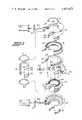
- FIG. 4is a sectional plan view taken substantially along the line 4--4 of FIG. 3;
- FIG. 5is a perspective view of the inner arm drive shaft of the illustrated robot
- FIG. 6is a perspective view of the outer arm drive shaft of the robot.
- FIG. 7is an exploded perspective view of one of the drive units of the illustrated robot.
- an industrial robot embodying the features of the present inventionis illustrated generally at 10 in FIG. 1.
- the robotis adapted for moving through six axes of revolution, and comprises a base or vertical support stand 12 having a horizontal waist 14 which is pivotally mounted for movement about the vertical axis A.
- An inner arm 16is pivotally mounted to the outer end of the waist 14 for movement about the horizontal axis B, and an outer arm 18 is pivotally mounted to the outer end of the inner arm for movement about the horizontal axis C.
- a wrist member 19is rotatably mounted at the end of the outer arm for rotation about the axis D, and a tong 20 is connected to the wrist by means of a pin 21 to permit movement about the axis E. Further, the tong 20 is rotatable about the rotational axis F.
- FIG. 2illustrates the drive unit 22 by which movement of the waist 14 relative to the stand about the axis A may be effected.
- other like drive units 24, 25are utilized to power each of two other movements of the robot.
- the unit 24is utilized for the movement of the inner arm 16 with respect to the waist about the axis B
- the unit 25is utilized for the movement of the outer arm with respect to the inner arm about the axis C.
- this standardization of drive unitsgreatly simplifies the design, construction, and repair of the overall apparatus, and promotes standardization of parts.
- the drive units for the other movements of the illustrated robotmay be generally conventional, and do not form a part of the present invention.
- the waist drive unit 22is mounted for rotation about the cylindrical post 28 which is fixed to the support stand 12 by a suitable connector 29, with the post 28 defining the vertical axis A.
- the unit 22comprises a pair of electrical stepping motors 30, 31 fixedly mounted to a bracket 32 which in turn forms the frame of the waist 14.
- Electrical stepping motorsare per se well-known in the art and are operated by discrete electrical pulses which are fed in a sequential manner from a suitable switching control system. For every pulse fed to the motor, the motor rotates a fixed angle, typically 1.8 degrees. Thus, the number of pulses fed to the motor determines the rotational angle the motor will make.
- a shaft encoderon the output shaft of the motor, which produces a verification signal upon each step having been taken.
- the two stepping motors 30, 31 of the unit 22are mounted to the bracket 32, with the output shafts of the two motors being disposed parallel to each other and extending in a direction which perpendicularly intersects the axis A.
- the two motors 30, 31each include a drive gear 34, 35 mounted at the end of the respective shaft.
- the two drive gears 34, 35preferably have an unequal number of teeth, with the number typically differing by one.
- the drive control for the two motors 30, 31 of the unit 22conforms to that illustrated schematically in FIG. 3, and includes a suitable switching apparatus or pulse generator 36, which in the illustrated embodiment is common for both motors of a drive unit. In other embodiments, a separate generator may be provided for each motor.
- the operation of the generator 36is controlled by a program 38 of a digital computer or the like.
- each motorpreferably includes a shaft encoder 40, which feeds a verification signal to a comparator 41 upon each rotational step of the associated motor. Should the comparator detect a failure of rotation, a suitable corrective signal is fed to the generator.
- the two motors 30, 31 of the unit 22are operatively interconnected to the vertical post 28 by means of a differential gear train.
- the differential gear trainincludes a pair of like, oppositely oriented gear wheels 44, 45, with each gear wheel being rotatably disposed coaxially about the post 28 for rotation about the axis A.
- Each gear wheel 44, 45includes two oppositely facing face gears 47, 48, with the outer face gear 47 of each wheel operatively meshing with respective ones of the drive gears 34, 35 and so that each motor is adapted to rotate its associated gear wheel about the axis A.
- a total of five pinion gears 50are mounted between the two gear wheels 44, 45, and so as to operatively mesh with the inner face gear 48 of each gear wheel.
- the two face gears 47, 48 on each gear wheelare each in the form of a circular rack, i.e. the faces of the gear teeth are coplaner and lie in a plane perpendicular to the axis A.
- This configurationfacilitates the alignment and assembly of the differential gear train, in that the gear wheels 44, 45 and drive gears 34, 35 are relatively movable along only a single vertical direction, rather than a plurality of directions as would be required by conventional bevel gears.
- the two gear wheels 44, 45are rotatably mounted on the post 28 between a pair of snap rings 52, which are held in the respective grooves 53 on the post.
- a spacer 54 and wave spring 55are disposed between each snap ring and adjacent gear wheel, so that the gear wheels are free to rotate and are axially biased toward each other and into operative meshing engagement with the five pinion gears.
- the five pinion gears 50are assembled to a planet carrier 58, by means of respective pinion shafts 59 which extend perpendicularly to the axis A. The inner end of each shaft is received in a mating radial opening 60 in the post 28.
- the planet carrier 58also supports a bearing 62, in cooperation with a bearing retainer ring 63 and the two mating support rings 65, 66.
- Upper and lower gear housings 68, 69serve to enclose the gears, with the two housings being fixed to each other and to the bracket 32 by suitable bolts (not shown).
- a motor mounting plate 72is utilized to secure each stepping motor to an associated housing, and a resilient sealing ring 73 is disposed between each housing 68, 69 and the post 28 adjacent the outer face of the housing.
- both motors 30, 31are operated at a corresponding speed and in a common direction by the pulses received from the generator 36. Since the gear wheels 44, 45 are oriented to face in opposite directions, with the motors on respective opposite sides, the gear wheels will rotate about the axis A in opposite directions. In view of the different number of teeth on the drive gears 34, 35, the pinions 50, which are locked to the vertical post 28 by their mounting shafts 59, will cause the motors 30, 31, bracket 32, and the waist 14 to all slowly rotate about the axis A.
- the waist 14may be rotated at a readily controllable high speed by either terminating operation of one motor or pulsing it at a fixed rate.
- the other motormay then be pulsed in a manner controlled by the computer program 38 to provide a desired acceleration, deceleration, or constant speed to the waist.
- only one motorneeds to be variably controlled to provide the desired movement.
- the motors and differential gear train for the drive unit 24 of the inner arm, and for the drive unit 25 of the outer arm,will be seen to be substantially identical to the above described construction.
- the motors and housings 68, 69 of these two drive unitsare fixed to the bracket 32.
- the shafts 59 of the pinions 50are disposed in openings 75 in the tubular drive shaft 76 (FIG. 5).
- the shaft 76is composed of two segments 76a and 76b, which are interconnected by a suitable connector 76c. Further, the shaft 76 is directly connected to the inner arm 16, and which is mounted to the bracket 32 for rotation about the axis B.
- the shafts 59 of the pinions 50are disposed in openings 78 in the inner drive shaft 79 (FIG. 6). More particularly, the drive shaft 79 includes an inner sleeve portion 80 which extends coaxially through the drive shaft 76 and mounts a suitable gear 81 at the remote free end thereof. In addition, the drive shaft 79 includes a second portion 82 which is disposed axially outside of the drive shaft 76 and has an outer diameter generally corresponding to that of the shaft 76. The inner sleeve portion 80 is interconnected to the second portion 82 by a suitable connector 83.
- each of the drive units 24, 25will be seen to be substantially identical to that described above with respect to the waist drive unit 22.
Landscapes
- Engineering & Computer Science (AREA)
- Robotics (AREA)
- Mechanical Engineering (AREA)
- Manipulator (AREA)
Abstract
Description
Claims (18)
Priority Applications (7)
| Application Number | Priority Date | Filing Date | Title |
|---|---|---|---|
| US06/346,222US4424473A (en) | 1982-02-05 | 1982-02-05 | Drive apparatus for an industrial robot |
| US06/443,156US4636138A (en) | 1982-02-05 | 1982-11-19 | Industrial robot |
| DE8383300373TDE3374671D1 (en) | 1982-02-05 | 1983-01-25 | Industrial robots, and arm assemblies and drive apparatus therefor |
| AT83300373TATE31043T1 (en) | 1982-02-05 | 1983-01-25 | INDUSTRIAL ROBOT, AS WELL AS BOOM AND DRIVE SYSTEM. |
| EP83300373AEP0086054B1 (en) | 1982-02-05 | 1983-01-25 | Industrial robots, and arm assemblies and drive apparatus therefor |
| JP58016844AJPS58160077A (en) | 1982-02-05 | 1983-02-03 | Industrial robot |
| US06/641,717US4645409A (en) | 1982-02-05 | 1984-08-16 | Outer arm assembly for industrial robot |
Applications Claiming Priority (1)
| Application Number | Priority Date | Filing Date | Title |
|---|---|---|---|
| US06/346,222US4424473A (en) | 1982-02-05 | 1982-02-05 | Drive apparatus for an industrial robot |
Related Child Applications (1)
| Application Number | Title | Priority Date | Filing Date |
|---|---|---|---|
| US06/443,156Continuation-In-PartUS4636138A (en) | 1982-02-05 | 1982-11-19 | Industrial robot |
Publications (1)
| Publication Number | Publication Date |
|---|---|
| US4424473Atrue US4424473A (en) | 1984-01-03 |
Family
ID=23358466
Family Applications (1)
| Application Number | Title | Priority Date | Filing Date |
|---|---|---|---|
| US06/346,222Expired - Fee RelatedUS4424473A (en) | 1982-02-05 | 1982-02-05 | Drive apparatus for an industrial robot |
Country Status (2)
| Country | Link |
|---|---|
| US (1) | US4424473A (en) |
| JP (1) | JPS58160077A (en) |
Cited By (13)
| Publication number | Priority date | Publication date | Assignee | Title |
|---|---|---|---|---|
| US4567417A (en)* | 1981-11-24 | 1986-01-28 | La Calhene, Societe Anonyme | Actuator |
| US4661966A (en)* | 1985-09-17 | 1987-04-28 | T-Bar Incorporated | Method and apparatus for adjusting transmission rates in data channels for use in switching systems |
| US4784010A (en)* | 1987-04-27 | 1988-11-15 | Graco Robotics Inc. | Electric robotic work unit |
| US4816730A (en)* | 1986-12-22 | 1989-03-28 | E. I. Du Pont De Nemours And Company | Autosampler |
| US5102377A (en)* | 1991-04-08 | 1992-04-07 | Stanley Spanski | Rotary actuator with epicyclic transmission |
| US5421218A (en)* | 1985-01-22 | 1995-06-06 | Fanuc Robotics North America, Inc. | Electric robot for use in a hazardous location |
| US5539266A (en)* | 1993-01-28 | 1996-07-23 | Applied Materials Inc. | Dual coaxial magnetic couplers for vacuum chamber robot assembly |
| US5583408A (en)* | 1989-10-20 | 1996-12-10 | Applied Materials | Two-axis magnetically coupled robot |
| US5678980A (en)* | 1989-10-20 | 1997-10-21 | Applied Materials, Inc. | Robot assembly |
| US6212968B1 (en)* | 1998-07-29 | 2001-04-10 | Janome Sewing Machine Co., Ltd, | SCARA robot |
| US6477913B1 (en) | 1985-01-22 | 2002-11-12 | Fanuc Robotics North America, Inc. | Electric robot for use in a hazardous location |
| US20120160811A1 (en)* | 2010-12-23 | 2012-06-28 | Randel Brandstrom | Apparatus for Applying Wear Coating in Conduit Elbows |
| CN109982816A (en)* | 2016-12-02 | 2019-07-05 | 日本电产三协株式会社 | Industrial robot |
Families Citing this family (4)
| Publication number | Priority date | Publication date | Assignee | Title |
|---|---|---|---|---|
| JPS62140794A (en)* | 1985-12-17 | 1987-06-24 | フアナツク株式会社 | Cable treater for industrial robot |
| US5065062A (en)* | 1988-10-20 | 1991-11-12 | Tokico Ltd. | Motor-drive industrial robot |
| JPH0531686A (en)* | 1991-07-24 | 1993-02-09 | Nissan Motor Co Ltd | Unit type robot |
| JP7343357B2 (en)* | 2019-10-25 | 2023-09-12 | ファナック株式会社 | Wrist shaft motor replacement jig and wrist shaft motor replacement method |
Citations (11)
| Publication number | Priority date | Publication date | Assignee | Title |
|---|---|---|---|---|
| US1667718A (en) | 1925-12-11 | 1928-05-01 | Edwin L Connell | Machine for driving nuts, screws, and the like |
| US1720018A (en) | 1926-04-19 | 1929-07-09 | Tubbs Ira Irl | Power-transmission means |
| US2417198A (en) | 1942-03-02 | 1947-03-11 | Hindmarch Thomas | Power drive |
| US2459253A (en) | 1944-11-29 | 1949-01-18 | Air Reduction | Reproducing apparatus |
| US2785369A (en) | 1951-08-01 | 1957-03-12 | David R Ligh | Driving arrangement and motor overload protection |
| US3146386A (en) | 1963-07-10 | 1964-08-25 | Gerber Scientific Instr Co | Stepping motor drive |
| GB1180500A (en) | 1967-06-09 | 1970-02-04 | Siemens Ag | A Combination of a Shaft and Driving Means for causing it to Rotate at a Speed Dictated by a Control Voltage Applied to the Driving Means |
| US3817403A (en) | 1972-05-10 | 1974-06-18 | Commissariat Energie Atomique | Remote manipulator |
| US4062455A (en) | 1976-11-22 | 1977-12-13 | Flatau Carl R | Remote manipulator |
| US4289996A (en) | 1978-08-29 | 1981-09-15 | Frazer Nash Limited | Actuators |
| US4300198A (en) | 1974-10-22 | 1981-11-10 | Giorgio Davini | Robot with light-weight, inertia-free programming device |
Family Cites Families (1)
| Publication number | Priority date | Publication date | Assignee | Title |
|---|---|---|---|---|
| JPS5751829Y2 (en)* | 1976-09-22 | 1982-11-11 |
- 1982
- 1982-02-05USUS06/346,222patent/US4424473A/ennot_activeExpired - Fee Related
- 1983
- 1983-02-03JPJP58016844Apatent/JPS58160077A/enactiveGranted
Patent Citations (11)
| Publication number | Priority date | Publication date | Assignee | Title |
|---|---|---|---|---|
| US1667718A (en) | 1925-12-11 | 1928-05-01 | Edwin L Connell | Machine for driving nuts, screws, and the like |
| US1720018A (en) | 1926-04-19 | 1929-07-09 | Tubbs Ira Irl | Power-transmission means |
| US2417198A (en) | 1942-03-02 | 1947-03-11 | Hindmarch Thomas | Power drive |
| US2459253A (en) | 1944-11-29 | 1949-01-18 | Air Reduction | Reproducing apparatus |
| US2785369A (en) | 1951-08-01 | 1957-03-12 | David R Ligh | Driving arrangement and motor overload protection |
| US3146386A (en) | 1963-07-10 | 1964-08-25 | Gerber Scientific Instr Co | Stepping motor drive |
| GB1180500A (en) | 1967-06-09 | 1970-02-04 | Siemens Ag | A Combination of a Shaft and Driving Means for causing it to Rotate at a Speed Dictated by a Control Voltage Applied to the Driving Means |
| US3817403A (en) | 1972-05-10 | 1974-06-18 | Commissariat Energie Atomique | Remote manipulator |
| US4300198A (en) | 1974-10-22 | 1981-11-10 | Giorgio Davini | Robot with light-weight, inertia-free programming device |
| US4062455A (en) | 1976-11-22 | 1977-12-13 | Flatau Carl R | Remote manipulator |
| US4289996A (en) | 1978-08-29 | 1981-09-15 | Frazer Nash Limited | Actuators |
Cited By (16)
| Publication number | Priority date | Publication date | Assignee | Title |
|---|---|---|---|---|
| US4567417A (en)* | 1981-11-24 | 1986-01-28 | La Calhene, Societe Anonyme | Actuator |
| US6477913B1 (en) | 1985-01-22 | 2002-11-12 | Fanuc Robotics North America, Inc. | Electric robot for use in a hazardous location |
| US5421218A (en)* | 1985-01-22 | 1995-06-06 | Fanuc Robotics North America, Inc. | Electric robot for use in a hazardous location |
| US4661966A (en)* | 1985-09-17 | 1987-04-28 | T-Bar Incorporated | Method and apparatus for adjusting transmission rates in data channels for use in switching systems |
| US4816730A (en)* | 1986-12-22 | 1989-03-28 | E. I. Du Pont De Nemours And Company | Autosampler |
| US4784010A (en)* | 1987-04-27 | 1988-11-15 | Graco Robotics Inc. | Electric robotic work unit |
| US5678980A (en)* | 1989-10-20 | 1997-10-21 | Applied Materials, Inc. | Robot assembly |
| US5583408A (en)* | 1989-10-20 | 1996-12-10 | Applied Materials | Two-axis magnetically coupled robot |
| US5879127A (en)* | 1989-10-20 | 1999-03-09 | Applied Materials, Inc. | Robot assembly |
| US5990585A (en)* | 1989-10-20 | 1999-11-23 | Applied Materials, Inc. | Two-axis magnetically coupled robot |
| US5102377A (en)* | 1991-04-08 | 1992-04-07 | Stanley Spanski | Rotary actuator with epicyclic transmission |
| US5539266A (en)* | 1993-01-28 | 1996-07-23 | Applied Materials Inc. | Dual coaxial magnetic couplers for vacuum chamber robot assembly |
| US6212968B1 (en)* | 1998-07-29 | 2001-04-10 | Janome Sewing Machine Co., Ltd, | SCARA robot |
| US20120160811A1 (en)* | 2010-12-23 | 2012-06-28 | Randel Brandstrom | Apparatus for Applying Wear Coating in Conduit Elbows |
| US8513559B2 (en)* | 2010-12-23 | 2013-08-20 | Swa Holding Company, Inc. | Apparatus for applying wear coating in conduit elbows |
| CN109982816A (en)* | 2016-12-02 | 2019-07-05 | 日本电产三协株式会社 | Industrial robot |
Also Published As
| Publication number | Publication date |
|---|---|
| JPS58160077A (en) | 1983-09-22 |
| JPH028877B2 (en) | 1990-02-27 |
Similar Documents
| Publication | Publication Date | Title |
|---|---|---|
| US4424473A (en) | Drive apparatus for an industrial robot | |
| US4047448A (en) | Robot head | |
| US4552505A (en) | Industrial robot having direct coaxial motor drive | |
| CA1257887A (en) | Outer arm assembly for industrial robot | |
| CA1172286A (en) | Three-axis wrist mechanism | |
| US5533418A (en) | Spherical robotic shoulder joint | |
| US4329111A (en) | Mechanical manipulator | |
| JP3326472B2 (en) | Articulated robot | |
| CA1262062A (en) | Gear unit for a manipulator | |
| US4636138A (en) | Industrial robot | |
| EP0048904B1 (en) | An industrial robot | |
| US4576544A (en) | Swivelling handle with three axes of rotation for an industrial robot | |
| EP0110347B1 (en) | Robot operation control system | |
| US4807486A (en) | Three-axes wrist mechanism | |
| US4703668A (en) | Wrist mechanism for a robot arm | |
| US4419041A (en) | Spacial mechanism and method | |
| GB1561260A (en) | Programmable manipulators | |
| JPH0583353B2 (en) | ||
| US4671732A (en) | Industrial robot | |
| CA2045487A1 (en) | Robotic manipulator | |
| EP3784446B1 (en) | A parallel kinematic robot | |
| US4062601A (en) | Self-contained modular pivot, notably for robots | |
| US4761114A (en) | Articulated head for an industrial robot and a robot equipped with a head of this type | |
| US4804304A (en) | Robot wrist | |
| EP0089129B1 (en) | A power transmission mechanism with a backlash regulator for industrial robots |
Legal Events
| Date | Code | Title | Description |
|---|---|---|---|
| AS | Assignment | Owner name:AMERICAN ROBOT CORPORATION, THE, WINSTON-SALEM, N. Free format text:ASSIGNMENT OF ASSIGNORS INTEREST.;ASSIGNOR:GORMAN, ROBERT H.;REEL/FRAME:003975/0277 Effective date:19820127 | |
| AS | Assignment | Owner name:AMERICAN ROBOT CORPORATION A PA CORP. Free format text:MERGER;ASSIGNOR:AMERICAN ROBOT CORPORATION THE, A NC CORP.;REEL/FRAME:004074/0548 Effective date:19820416 Owner name:AMERICAN ROBOT CORPORATION A PA CORP., PENNSYLVANI Free format text:MERGER;ASSIGNOR:AMERICAN ROBOT CORPORATION THE, A NC CORP.;REEL/FRAME:004074/0548 Effective date:19820416 | |
| MAFP | Maintenance fee payment | Free format text:PAYMENT OF MAINTENANCE FEE, 4TH YEAR, PL 96-517 (ORIGINAL EVENT CODE: M170); ENTITY STATUS OF PATENT OWNER: SMALL ENTITY Year of fee payment:4 | |
| FEPP | Fee payment procedure | Free format text:PAYOR NUMBER ASSIGNED (ORIGINAL EVENT CODE: ASPN); ENTITY STATUS OF PATENT OWNER: SMALL ENTITY | |
| AS | Assignment | Owner name:AMERICAN CIMFLEX CORPORATION Free format text:CHANGE OF NAME;ASSIGNOR:AMERICAN ROBOT CORPORATION;REEL/FRAME:005262/0127 Effective date:19860402 Owner name:CIMFLEX TEKNOWLEDGE CORPORATION Free format text:CHANGE OF NAME;ASSIGNOR:TEKNOWLEDGE, INC., THE;REEL/FRAME:005262/0122 Effective date:19890307 Owner name:TEKNOWLEDGE, INC., A CORP. OF DE. Free format text:MERGER;ASSIGNOR:AMERICAN CIMFLEX CORPORATION;REEL/FRAME:005262/0120 Effective date:19890224 | |
| FEPP | Fee payment procedure | Free format text:MAINTENANCE FEE REMINDER MAILED (ORIGINAL EVENT CODE: REM.); ENTITY STATUS OF PATENT OWNER: SMALL ENTITY | |
| LAPS | Lapse for failure to pay maintenance fees | ||
| AS | Assignment | Owner name:AMERICAN ROBOT CORPORATION, A PA CORP., PENNSYLVAN Free format text:ASSIGNMENT OF ASSIGNORS INTEREST.;ASSIGNOR:CIMFLEX TEKNOWLEDGE CORPORATION, A DE CORP.;REEL/FRAME:006021/0350 Effective date:19920131 | |
| FP | Lapsed due to failure to pay maintenance fee | Effective date:19911229 | |
| AS | Assignment | Owner name:EVEREADY BATTERY COMPANY, INC., MISSOURI Free format text:ASSIGNMENT OF ASSIGNORS INTEREST;ASSIGNOR:GATES ENERGY PRODUCTS, INC. A CORP. OF COLORADO;REEL/FRAME:006713/0701 Effective date:19930827 | |
| STCH | Information on status: patent discontinuation | Free format text:PATENT EXPIRED DUE TO NONPAYMENT OF MAINTENANCE FEES UNDER 37 CFR 1.362 |