US4423892A - Swivelable quick connector assembly - Google Patents
Swivelable quick connector assemblyDownload PDFInfo
- Publication number
- US4423892A US4423892AUS06/201,711US20171180AUS4423892AUS 4423892 AUS4423892 AUS 4423892AUS 20171180 AUS20171180 AUS 20171180AUS 4423892 AUS4423892 AUS 4423892A
- Authority
- US
- United States
- Prior art keywords
- housing
- conduit
- connector assembly
- retainer
- ring
- Prior art date
- Legal status (The legal status is an assumption and is not a legal conclusion. Google has not performed a legal analysis and makes no representation as to the accuracy of the status listed.)
- Expired - Lifetime
Links
- 238000003780insertionMethods0.000claimsabstractdescription8
- 230000037431insertionEffects0.000claimsabstractdescription8
- 239000012530fluidSubstances0.000claimsdescription21
- 230000000903blocking effectEffects0.000claimsdescription9
- 239000012858resilient materialSubstances0.000claimsdescription8
- 239000002184metalSubstances0.000claimsdescription4
- 229910052751metalInorganic materials0.000claimsdescription4
- 238000007789sealingMethods0.000claims3
- 230000004323axial lengthEffects0.000claims2
- 125000006850spacer groupChemical group0.000description6
- 230000007797corrosionEffects0.000description3
- 238000005260corrosionMethods0.000description3
- 238000010276constructionMethods0.000description2
- 238000000926separation methodMethods0.000description2
- 239000004020conductorSubstances0.000description1
- 230000008878couplingEffects0.000description1
- 238000010168coupling processMethods0.000description1
- 238000005859coupling reactionMethods0.000description1
- 230000003247decreasing effectEffects0.000description1
- 239000003792electrolyteSubstances0.000description1
- 239000000446fuelSubstances0.000description1
- 239000007788liquidSubstances0.000description1
- 239000000463materialSubstances0.000description1
- 150000002739metalsChemical class0.000description1
- 230000004048modificationEffects0.000description1
- 238000012986modificationMethods0.000description1
- 239000012811non-conductive materialSubstances0.000description1
- 239000003507refrigerantSubstances0.000description1
Images

Classifications
- F—MECHANICAL ENGINEERING; LIGHTING; HEATING; WEAPONS; BLASTING
- F16—ENGINEERING ELEMENTS AND UNITS; GENERAL MEASURES FOR PRODUCING AND MAINTAINING EFFECTIVE FUNCTIONING OF MACHINES OR INSTALLATIONS; THERMAL INSULATION IN GENERAL
- F16L—PIPES; JOINTS OR FITTINGS FOR PIPES; SUPPORTS FOR PIPES, CABLES OR PROTECTIVE TUBING; MEANS FOR THERMAL INSULATION IN GENERAL
- F16L37/00—Couplings of the quick-acting type
- F16L37/08—Couplings of the quick-acting type in which the connection between abutting or axially overlapping ends is maintained by locking members
- F16L37/084—Couplings of the quick-acting type in which the connection between abutting or axially overlapping ends is maintained by locking members combined with automatic locking
- F16L37/098—Couplings of the quick-acting type in which the connection between abutting or axially overlapping ends is maintained by locking members combined with automatic locking by means of flexible hooks
- F16L37/0985—Couplings of the quick-acting type in which the connection between abutting or axially overlapping ends is maintained by locking members combined with automatic locking by means of flexible hooks the flexible hook extending radially inwardly from an outer part and engaging a bead, recess or the like on an inner part
- F16L37/0987—Couplings of the quick-acting type in which the connection between abutting or axially overlapping ends is maintained by locking members combined with automatic locking by means of flexible hooks the flexible hook extending radially inwardly from an outer part and engaging a bead, recess or the like on an inner part the flexible hook being progressively compressed by axial tensile loads acting on the coupling
- F—MECHANICAL ENGINEERING; LIGHTING; HEATING; WEAPONS; BLASTING
- F16—ENGINEERING ELEMENTS AND UNITS; GENERAL MEASURES FOR PRODUCING AND MAINTAINING EFFECTIVE FUNCTIONING OF MACHINES OR INSTALLATIONS; THERMAL INSULATION IN GENERAL
- F16L—PIPES; JOINTS OR FITTINGS FOR PIPES; SUPPORTS FOR PIPES, CABLES OR PROTECTIVE TUBING; MEANS FOR THERMAL INSULATION IN GENERAL
- F16L37/00—Couplings of the quick-acting type
- F16L37/08—Couplings of the quick-acting type in which the connection between abutting or axially overlapping ends is maintained by locking members
- F16L37/12—Couplings of the quick-acting type in which the connection between abutting or axially overlapping ends is maintained by locking members using hooks, pawls, or other movable or insertable locking members
- F16L37/14—Joints secured by inserting between mating surfaces an element, e.g. a piece of wire, a pin, a chain
- F16L37/142—Joints secured by inserting between mating surfaces an element, e.g. a piece of wire, a pin, a chain where the securing element is inserted tangentially
- F16L37/144—Joints secured by inserting between mating surfaces an element, e.g. a piece of wire, a pin, a chain where the securing element is inserted tangentially the securing element being U-shaped
- Y—GENERAL TAGGING OF NEW TECHNOLOGICAL DEVELOPMENTS; GENERAL TAGGING OF CROSS-SECTIONAL TECHNOLOGIES SPANNING OVER SEVERAL SECTIONS OF THE IPC; TECHNICAL SUBJECTS COVERED BY FORMER USPC CROSS-REFERENCE ART COLLECTIONS [XRACs] AND DIGESTS
- Y10—TECHNICAL SUBJECTS COVERED BY FORMER USPC
- Y10S—TECHNICAL SUBJECTS COVERED BY FORMER USPC CROSS-REFERENCE ART COLLECTIONS [XRACs] AND DIGESTS
- Y10S285/00—Pipe joints or couplings
- Y10S285/921—Snap-fit
- Y—GENERAL TAGGING OF NEW TECHNOLOGICAL DEVELOPMENTS; GENERAL TAGGING OF CROSS-SECTIONAL TECHNOLOGIES SPANNING OVER SEVERAL SECTIONS OF THE IPC; TECHNICAL SUBJECTS COVERED BY FORMER USPC CROSS-REFERENCE ART COLLECTIONS [XRACs] AND DIGESTS
- Y10—TECHNICAL SUBJECTS COVERED BY FORMER USPC
- Y10S—TECHNICAL SUBJECTS COVERED BY FORMER USPC CROSS-REFERENCE ART COLLECTIONS [XRACs] AND DIGESTS
- Y10S285/00—Pipe joints or couplings
- Y10S285/924—Vented
Definitions
- the present inventionrelates to a connector assembly for providing a swivelable quick connection.
- Another object of the present inventionis to provide a pre-assembled connector housing and retainer element so that a snapping connection may be made to a tubular fluid conveying conduit.
- Another object of the present inventionis to provide a connector assembly that may be employed to join dissimilar electrically conducting materials that would be otherwise subject to galvanic corrosion.
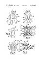
- FIG. 1is a perspective assembly view of a first embodiment of the present invention.
- FIG. 2is a side elevation view, partially in cross-section, of the connector assembly of FIG. 1.
- FIG. 3is another view of the connector assembly of FIG. 2, shown in the bleed-down position.
- FIG. 4is a perspective view of a second embodiment of a retainer element according to the present invention.
- FIG. 5is a front elevation view of a third embodiment of a retainer element according to the present invention.
- FIG. 6is a front elevation view of a fourth embodiment of a retainer element accordig to the present invention.
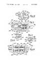
- FIG. 7is a front elevation view of the retainer element of FIG. 6 coupled to a housing according to the present invention.
- FIG. 8is a side elevation view, partially in cross-section, of the retainer element and housing of FIG. 7.
- FIG. 9is a side elevation view, partially in cross-section, of another embodiment of the connector assembly according to the present invention.
- FIG. 10is a perspective view of a fifth embodiment of a retainer element, and its relationship to a conduit is illustrated.
- FIG. 11is a side elevation view of another embodiment of the connector assembly according to the present invention.
- FIG. 12is a perspective view of the retainer element of FIG. 11.
- FIG. 13is a perspective view of another embodiment of the retainer element for the connector assembly of FIG. 11.
- FIG. 14is a side elevation view, partially in cross-section of another embodiment of the connector assembly according to the present invention.
- the connector assemblyis generally comprised of a tubular conduit 12 adapted to convey fluid, a housing 14, and a retainer element 16.
- Conduit 12is provided with an outwardly projecting annular surface 18 displaced from a beveled connecting end 20 of the conduit.
- Annular surface 18is formed with a blocking wall portion 22 disposed transversely or perpendicularly to a central axis 24 of conduit 12, and a sloping wall portion 26 gradually increasing from an outer surface 28 of the conduit.
- Housing 14may have any suitable outer surface shape, and in one form of the present invention, the housing is provided with an enlarged diameter portion 30, a reduced diameter portion 32, and a third diameter portion 34.
- the housingis adapted to provide for apertures or openings 36 a-d, which are equidistantly spaced around the circumference of enlarged portion 30 of the housing.
- Apertures 36are provided to receive and position retainer element 16 transversely to axis 24 of the conduit.
- the retainer elementis made from a resilient material, such as plastic, and is comprised of a pair of generally parallel elongated legs 38 joined at one end by a cross member 40, which provides a separation between the legs approximately equal to the outside diameter of conduit 12.
- Each retainer leg 38includes a sloping lead area 42 formed in the interior side of the leg, and a barb 44 projecting from the exterior side of the leg.
- each retainer legfurther includes a first recess 46 and a second recess 48 formed in the front side of the leg.
- Housing 14is shown to be formed with a central bore 50, having an enlarged diameter portion 52, a reduced diameter portion 54, and a third diameter portion 56.
- Housing 14also includes a bushing 58 and an elastomeric ring 60 disposed in third diameter portion 56 of housing central bore 50.
- Bushing 58also includes a flange portion 62, which extends into enlarged diameter portion 52 of central bore 50.
- a surface 64 of flange portion 62is shaped to provide a slope corresponding to sloping wall portion 26 of conduit 12.
- connector assembly 10may be connected by first coupling retainer element 16 to housing 14, and then inserting connecting end 20 of conduit 12 into central bore 50 of the housing.
- Retainer element 16is coupled to housing 14 by inserting legs 38 into apertures 36a and 36b and out through apertures 36c and 36d until barbs 44 extend through apertures 36c and 36d.
- Barbs 44projects outwardly a distance sufficient to engage the upper edges of apertures 36c and 36d and prevent the removal of the retainer element from the housing.
- Apertures 36 a-dare shaped sufficiently large to permit both an inward and outward deflection of retainer legs 38.
- retainer legs 16When retainer element 16 is being inserted into housing 14, the retainer legs deflect inwardly to permit barbs 44 to entend through apertures 36c and 36d.
- connecting end 20 of conduit 12When connecting end 20 of conduit 12 is being inserted into bore 50 of housing 14, the retainer legs deflect outwardly to permit annular surface 18 to translate past the retainer legs. Sloping wall portion 26 of annular surface 18 cooperates with sloping lead area 42 of retainer legs 38 to reduce the force required to translate the annular surface past the retainer legs.
- retainer legs 38After conduit 12 is fully inserted into central bore 50 of housing 14, as shown in FIG. 2, retainer legs 38 cooperate with blocking wall portion 22 of annular surface 18 to resist the disconnection or removal of conduit 12 from housing 14.
- housing 14An important feature of housing 14 is elastomeric ring 60.
- This ringprovides a fluid tight seal between conduit 12 and housing 14, and yet permits the conduit to rotate of swivel relative to the housing.
- Ring 60is positioned transversely to axis 24 of conduit 12 by bushing 58.
- Flange portion 62 of bushing 58provides a means for impeding further insertion of conduit 12 within central bore 50 when surface 64 of flange portion 62 contacts sloping wall portion 26 of annular surface 26 of the conduit.
- FIG. 3another view of connector assembly 10 is shown.
- the connector assemblyis illustrated in the "bleed-down" position.
- This feature of the inventionmay be used to safely disconnect conduit 12 from housing 14 when the fluid pressure is greater than ambient.
- retainer element 16is partially removed or lifted up to the point where first and second recesses, 46 and 48 respectively, permit the retainer element to be translated toward a first end 66 of housing 14, in the direction of the arrows shown in FIG. 2.
- Surfaces 68 and 70 of the retainer recesseswill engage the vertical edges of apertures 36 a-d adjacent to housing end 66, and prevent further axial translation of retainer element 16.
- Conduit 12may then also be translated toward housing end 66, past the point where elastomeric ring 60 contacts conduit end 20.
- retainer element 74is similar to retainer element 16, and the reference numerals for the corresponding components are the same.
- retainer element 74is an integral element, formed in any conventional manner from a resilient material, such as plastic. The difference between these retainers resides in the lead areas formed in the sides of legs 38.
- Retainer element 74is formed with an annular outwardly extending lead area 76 in each of the legs. Lead areas 76 have approximately the same thickness as the thickness of legs 38. Lead areas 76 may extend to the back surface of retainer element 74, or may only partially extend the width of legs 38, as shown in FIG. 4 at reference numeral 78.
- lead areas 42 of retainer element 16do not outwardly extend. Rather, lead areas 42 are recessed in the interior sides of legs 38 for retainer element 16. Thus, the thickness of legs 38 for retainer element 16 is reduced at the front surface of the legs, and gradually increases to the normal leg thickness at the back surface.
- Retainer element 80is also intended for use with housing 14 shown in FIG. 1.
- Retainer element 80is made from a resilient material, and is comprised of a pair of generally parallel elongated legs 82 joined at one end by a cross number 84, which is extended to form annular members 86. These annular members generally conform to and partially encircle the outside surface of enlarge diameter portion 30 of housing 14. Annular members 86 are each formed with a barb 88 and a handle 90.
- Legs 82are each formed with a lead area 92 similar in shape to lead area 42 for legs 38 of retainer element 16.
- Retainer element 80is coupled to housing 14 by inserting legs 82 into apertures 36a and 36b and out through apertures 36c and 36d. As legs 82 are being inserted, annular members 86 deflect outwardly to permit their translation around the outside surface of housing 14. When the retainer element is fully inserted, barbs 88 will extend inwardly into apertures 36c and 36d to lock the retainer element in place. Handles 90 are used to assist the removal of retainer element 80 from housing 14, which is achieved by deflecting annular member 86 outwardly to disengage barbs 88 from the apertures and lifting the retainer element out from the housing.
- retainer element 94may be used with housing 14, and is made from a resilient material.
- Retainer element 94is comprised of a pair of generally parallel elongated legs 96 joined at one end by a cross member 98. Legs 96 are each formed with an inwardly extending barb 100, and a lead area 102 similar in shape to lead area 42 of retainer element 16.
- Retainer element 94is coupled to housing 14 by deflecting legs 96 outwardly a sufficient distance to permit their insertion into apertures 36a and 36b and out through apertures 36c and 36d. When fully inserted, barbs 100 engage the lower lateral edges of apertures 36c and 36d to lock retainer element 94 in place.
- FIGS. 7 and 8retainer element 94 is shown coupled to a housing 104, similar in construction to housing 14.
- FIG. 7is a front elevation view and FIG. 8 is a side elevation view partially in cross-section.
- Housing 104is provided with an enlarged diameter portion 106 at a first end 108 for receiving a conduit and for mounting retainer element 94, and a reduced diameter portion 110 at a second end 112 for providing a fluid path.
- Housing 104is also provided with a third diameter portion 114 interposed between enlarged diameter portion 106 and reduced diameter portion 110.
- Housing 104further includes a bushing 116, two elastomeric rings 118 and 120, and an annular sleeve 122 for separating the rings.
- This housingillustrates that more than one elastomeric ring may be employed to provide a fluid tight seal, as may be required for the particular application of the connector assembly.
- FIG. 9another embodiment of a connector assembly 124 according to the present invention is shown.
- This embodimentillustrates a housing 126 that may be employed to provide a fluid tight connection between a tubular conduit 128 and a metallic tubular conduit 130.
- conduit 128includes an outwardly projecting annular surface 132, which is formed with a blocking wall portion 134 and a sloping wall portion 136.
- Conduit 130is formed with an enlarged diameter portion 138, which provides the third diameter portion of the above described housings 14 and 104.
- Housing 126is provided with a bushing 140, an elastomeric ring 142, and a spacer 144 mounted in enlarged diameter portion 138 of conduit 130.
- Both bushing 140 and spacer 144are made from an electrically non-conductive material, such as plastic, and serve an important function when both conduits 128 and 130 are made from dissimilar metals subject to galvanic corrosion.
- Bushing 140 and spacer 144support conduit 128 within housing 126 and preclude an end 146 of conduit 128 from contacting a reduced diameter portion 148 of conduit 130.
- the fluid being conveyedis a liquid having the properties of an electrolyte
- bushing 140 and spacer 144prevent the completion of a circuit loop which would allow a corrosion current to flow.
- Housing 126, as well as housings 14 and 104may be made from either plastic or metal. Any of the retainer elements 16, 74, 80, or 94 may be coupled with housing 126 in the manner described above.
- a fifth embodiment of a retainer element 150is shown in relation to a conduit 152.
- Retainer element 150is comprised of two wedge shaped members 154 and 156, which combine to form a jam fit against the blocking wall portion (not shown) of an annular surface 158 of conduit 152.
- Wedge member 156is comprised of a pair of generally parallel elongated legs 160 joined at one end by a cross member 162.
- wedge member 154is comprised of a pair of generally parallel elongated legs 164 joined at one end by a cross member 166.
- Wedge member 156further includes an outwardly extending barb 168 formed at the end of each of legs 160.
- wedge member 154includes an outwardly extending barb 170 formed in the side of each of legs 164.
- the sides of the legs 160 and 164 where wedge members 156 and 154 are joinedare reciprocably slanted and formed with serrations, as indicated generally at reference number 172.
- Retainer element 150may be coupled to a housing, such as housing 14 of FIG. 1 to force annular surface 158 of conduit 152 securely against a bushing, such as bushing 58 of FIG. 2.
- Retainer element 150may be coupled to housing 14 by inserting legs 164 of wedge member 154 into apertures 36a and 36b, and inserting legs 160 of wedge member 156 into apertures 36c and 36d in a similar manner to that described above for retainer element 16.
- conduit 152may be inserted into housing 14 before the wedge members are coupled to the housing.
- FIG. 12illustrates a perspective view of a retainer element 176
- FIG. 11illustrates a side elevation view, partially in cross-section, of the fully assembled connector assembly.
- Connector assembly 174is comprised of a tubular conduit 178, a housing 180, and retainer element 176.
- Housing 180may be made from any suitable material, such as plastic or metal, and may have any appropriate outer shape, such as a cylinder or hex construction. Housing 180 is formed with a central bore 182, which provides an enlarged diameter portion 184, a reduced diameter portion 186, and a third diameter portion 188.
- Housing 180further includes an inwardly extending flange 190, forming a forth diameter portion, for mounting retainer element 176 to the housing.
- Flange 190may have a slant shape as shown in FIG. 11 or may have a flat surface.
- Housing 180is also provided with a bushing 192, two elastomeric rings 194 and 196, a sleeve 198, and a spacer 200 generally mounted in third diameter portion 188.
- Retainer element 176is made from a resilient material, and is comprised of a pair of opposing annular leg members 202 and 204 centrally joined by a recessed ring 206, which positions the retainer element at flange 190 of housing 180.
- Annular leg 202is formed with a radially extending tab end 208 on one side of recessed ring 206 and a radially converging jaw end 210 on the other side of the recessed ring.
- annular leg 204is formed with a radially extending tab 212 on one side of recessed ring 206 and a radially converging jaw 214 on the other side.
- the distance between annular leg members 202 and 204 at the converging endscorresponds approximately to the outside diameter of conduit 178.
- Retainer element 176is coupled to housing 180 by insertion into central bore 182 until flange 190 engages or straddles recessed ring 206.
- Conduit 178is then inserted into central bore 182 with an insertion force sufficient to deflect converging jaw ends 210 and 214 outwardly to permit an annular surface 216 of the conduit to be translated passed retainer element 176.
- Conduit 178may be removed from housing 180 by compressing extending tab ends 208 and 212 together sufficiently to extend converging jaw ends 210 and 214 apart, so that the conduit may be extracted from the housing without having to remove retainer element 176.
- Retainer element 220is made from a resilient material, and is comprised of a ring 222 for mounting the retainer element on flange 190 of housing 180, a pair of opposing jaws 224 and 226 projecting from one side of the ring, and a pair of tabs 228 and 230 projecting from the other side of the ring and positioned on opposite sides of the jaws.
- Ring 222is formed with an outer diameter approximately corresponding to the bore diameter provided by flange 190 of housing 180.
- Jaws 224 and 226extend beyond the outer diameter of ring 222 at an end 232 and converge at another end 234 to provide a separation approximately corresponding to the outside diameter of conduit 178.
- retainer element 220When retainer element 220 is coupled to housing 180, flange 190 is interposed between tabs 228 and 230, and extending end of jaws 224 and 226.
- Retainer element 220operates to maintain conduit 178 in housing 178 in a similar manner to that described above for retainer element 176.
- retainer element 220is of a simplified design in that the retainer element is not provided with an integral means to assist the removal of conduit 178 from housing 180.
- Connector assembly 236represents a union-type connector, and is essentially a duplicate of the structure described above for the previous embodiments.
- connector assembly 236is comprised of two conduits 238 and 240, a housing 242, and a pair of retainer elements 244 and 246.
- Housing 242includes a pair of bushings 248 and 250, a set of four elastomeric rings 252-258, a pair of sleeves 260 and 262, and a central spacer 264.
Landscapes
- Engineering & Computer Science (AREA)
- General Engineering & Computer Science (AREA)
- Mechanical Engineering (AREA)
- Quick-Acting Or Multi-Walled Pipe Joints (AREA)
Abstract
Description
The present invention relates to a connector assembly for providing a swivelable quick connection.
In the automotive industry, as well as for many other industries, the need always exists for low-cost, reliable, and easy to assemble components. This need is especially apparent with respect to providing a connection between fluid carrying conduits, such as a fuel or refrigerant lines. In older threaded connectors, substantial assembly time could be accumulated in screwing on a cap to a fitting and tightening the cap down to the proper toreque needed to provide for a fluid tight seal. Further, an inventory would have to be maintained to keep track of the number of caps and fittings, and any liners or other components that may be necessary. Also, retightening of the caps may be required to maintain the seal after the automobilie or other system has been put in use.
Accordingly, it is the primary object of the present invention to provide an improved connector assembly for providing a swivelable quick connection between fluid conveying conduits.
In addition, it is an object of the present invention to provide a pre-assembled connector housing and retainer element so that a connecion to a tubular fluid conveying conduit may be made in one step without resorting to any tools.
Another object of the present invention is to provide a pre-assembled connector housing and retainer element so that a snapping connection may be made to a tubular fluid conveying conduit.
Another object of the present invention is to provide a connector assembly that may be employed to join dissimilar electrically conducting materials that would be otherwise subject to galvanic corrosion.
It is a further object of the present invention to provide a connector assembly which is adapted to provide a for a bleed-down position when disconnecting a conduit from the housing of the connector assembly.
Additional objects and advantages of the present invention will become apparent from a reading of the detailed description of the preferred embodiments which makes reference to the following set of drawings in which:
FIG. 1 is a perspective assembly view of a first embodiment of the present invention.
FIG. 2 is a side elevation view, partially in cross-section, of the connector assembly of FIG. 1.
FIG. 3 is another view of the connector assembly of FIG. 2, shown in the bleed-down position.
FIG. 4 is a perspective view of a second embodiment of a retainer element according to the present invention.
FIG. 5 is a front elevation view of a third embodiment of a retainer element according to the present invention.
FIG. 6 is a front elevation view of a fourth embodiment of a retainer element accordig to the present invention.
FIG. 7 is a front elevation view of the retainer element of FIG. 6 coupled to a housing according to the present invention.
FIG. 8 is a side elevation view, partially in cross-section, of the retainer element and housing of FIG. 7.
FIG. 9 is a side elevation view, partially in cross-section, of another embodiment of the connector assembly according to the present invention.
FIG. 10 is a perspective view of a fifth embodiment of a retainer element, and its relationship to a conduit is illustrated.
FIG. 11 is a side elevation view of another embodiment of the connector assembly according to the present invention.
FIG. 12 is a perspective view of the retainer element of FIG. 11.
FIG. 13 is a perspective view of another embodiment of the retainer element for the connector assembly of FIG. 11.
FIG. 14 is a side elevation view, partially in cross-section of another embodiment of the connector assembly according to the present invention.
Referring to FIG. 1, a perspective assembly view of aconnector assembly 10 according to the present invention is shown. The connector assembly is generally comprised of atubular conduit 12 adapted to convey fluid, ahousing 14, and aretainer element 16.Conduit 12 is provided with an outwardly projecting annular surface 18 displaced from a beveled connectingend 20 of the conduit. Annular surface 18 is formed with a blockingwall portion 22 disposed transversely or perpendicularly to acentral axis 24 ofconduit 12, and a sloping wall portion 26 gradually increasing from anouter surface 28 of the conduit.Housing 14 may have any suitable outer surface shape, and in one form of the present invention, the housing is provided with anenlarged diameter portion 30, a reduceddiameter portion 32, and athird diameter portion 34. The housing is adapted to provide for apertures or openings 36 a-d, which are equidistantly spaced around the circumference ofenlarged portion 30 of the housing. Apertures 36 are provided to receive andposition retainer element 16 transversely toaxis 24 of the conduit. The retainer element is made from a resilient material, such as plastic, and is comprised of a pair of generally parallelelongated legs 38 joined at one end by across member 40, which provides a separation between the legs approximately equal to the outside diameter ofconduit 12. Eachretainer leg 38 includes asloping lead area 42 formed in the interior side of the leg, and abarb 44 projecting from the exterior side of the leg. In addition, each retainer leg further includes afirst recess 46 and asecond recess 48 formed in the front side of the leg.
Referring to FIG. 2, a side elevation view ofconnector assembly 10 is shown, partially in cross-section in a fully assembled position.Housing 14 is shown to be formed with a central bore 50, having an enlarged diameter portion 52, a reduceddiameter portion 54, and athird diameter portion 56.Housing 14 also includes abushing 58 and anelastomeric ring 60 disposed inthird diameter portion 56 of housing central bore 50.Bushing 58 also includes a flange portion 62, which extends into enlarged diameter portion 52 of central bore 50. Asurface 64 of flange portion 62 is shaped to provide a slope corresponding to sloping wall portion 26 ofconduit 12.
In the preferred embodiment,connector assembly 10 may be connected by firstcoupling retainer element 16 tohousing 14, and then inserting connectingend 20 ofconduit 12 into central bore 50 of the housing.Retainer element 16 is coupled tohousing 14 by insertinglegs 38 into apertures 36a and 36b and out throughapertures 36c and 36d untilbarbs 44 extend throughapertures 36c and 36d.Barbs 44 projects outwardly a distance sufficient to engage the upper edges ofapertures 36c and 36d and prevent the removal of the retainer element from the housing. Apertures 36 a-d are shaped sufficiently large to permit both an inward and outward deflection ofretainer legs 38. Whenretainer element 16 is being inserted intohousing 14, the retainer legs deflect inwardly to permitbarbs 44 to entend throughapertures 36c and 36d. When connectingend 20 ofconduit 12 is being inserted into bore 50 ofhousing 14, the retainer legs deflect outwardly to permit annular surface 18 to translate past the retainer legs. Sloping wall portion 26 of annular surface 18 cooperates with slopinglead area 42 ofretainer legs 38 to reduce the force required to translate the annular surface past the retainer legs. Afterconduit 12 is fully inserted into central bore 50 ofhousing 14, as shown in FIG. 2,retainer legs 38 cooperate with blockingwall portion 22 of annular surface 18 to resist the disconnection or removal ofconduit 12 fromhousing 14.
An important feature ofhousing 14 iselastomeric ring 60. This ring provides a fluid tight seal betweenconduit 12 andhousing 14, and yet permits the conduit to rotate of swivel relative to the housing.Ring 60 is positioned transversely toaxis 24 ofconduit 12 bybushing 58. Flange portion 62 ofbushing 58 provides a means for impeding further insertion ofconduit 12 within central bore 50 whensurface 64 of flange portion 62 contacts sloping wall portion 26 of annular surface 26 of the conduit.
Referring to FIG. 3, another view ofconnector assembly 10 is shown. Here, the connector assembly is illustrated in the "bleed-down" position. This feature of the invention may be used to safely disconnectconduit 12 fromhousing 14 when the fluid pressure is greater than ambient. Accordingly,retainer element 16 is partially removed or lifted up to the point where first and second recesses, 46 and 48 respectively, permit the retainer element to be translated toward a first end 66 ofhousing 14, in the direction of the arrows shown in FIG. 2.Surfaces retainer element 16.Conduit 12 may then also be translated toward housing end 66, past the point whereelastomeric ring 60 contacts conduit end 20. This will interrupt the fluid tight seal, and permit the pressure of the fluid to rapidly decrease. When this seal is broken,legs 38 ofretainer element 16 will prevent the total ejection of the conduit from the housing under the force of the fluid pressure by engaging blockingwall portion 22 of annular surface 18. After the fluid pressure has decreased to the ambient pressure, the conduit may then be translated back toward a second end 72 of the housing, so that the retainer element may be removed. The conduit may then be removed from the housing without any obstruction.
Referring to FIG. 4, a second embodiment of a retainer element 74 is shown. Retainer element 74 is similar toretainer element 16, and the reference numerals for the corresponding components are the same. As in the case ofretainer element 16, retainer element 74 is an integral element, formed in any conventional manner from a resilient material, such as plastic. The difference between these retainers resides in the lead areas formed in the sides oflegs 38. Retainer element 74 is formed with an annular outwardly extending lead area 76 in each of the legs. Lead areas 76 have approximately the same thickness as the thickness oflegs 38. Lead areas 76 may extend to the back surface of retainer element 74, or may only partially extend the width oflegs 38, as shown in FIG. 4 atreference numeral 78. In contrast,lead areas 42 ofretainer element 16 do not outwardly extend. Rather, leadareas 42 are recessed in the interior sides oflegs 38 forretainer element 16. Thus, the thickness oflegs 38 forretainer element 16 is reduced at the front surface of the legs, and gradually increases to the normal leg thickness at the back surface.
Referring to FIG. 5, a third embodiment of aretainer element 80 is shown.Retainer element 80 is also intended for use withhousing 14 shown in FIG. 1.Retainer element 80 is made from a resilient material, and is comprised of a pair of generally parallelelongated legs 82 joined at one end by across number 84, which is extended to formannular members 86. These annular members generally conform to and partially encircle the outside surface of enlargediameter portion 30 ofhousing 14.Annular members 86 are each formed with abarb 88 and a handle 90.Legs 82 are each formed with alead area 92 similar in shape to leadarea 42 forlegs 38 ofretainer element 16.
Referring to FIG. 6, a fourth embodiment of aretainer element 94 is shown. Again, retainer element may be used withhousing 14, and is made from a resilient material.Retainer element 94 is comprised of a pair of generally parallelelongated legs 96 joined at one end by across member 98.Legs 96 are each formed with an inwardly extending barb 100, and alead area 102 similar in shape to leadarea 42 ofretainer element 16.Retainer element 94 is coupled tohousing 14 by deflectinglegs 96 outwardly a sufficient distance to permit their insertion into apertures 36a and 36b and out throughapertures 36c and 36d. When fully inserted, barbs 100 engage the lower lateral edges ofapertures 36c and 36d to lockretainer element 94 in place.
Referring to FIGS. 7 and 8,retainer element 94 is shown coupled to ahousing 104, similar in construction tohousing 14. FIG. 7 is a front elevation view and FIG. 8 is a side elevation view partially in cross-section.Housing 104 is provided with anenlarged diameter portion 106 at afirst end 108 for receiving a conduit and for mountingretainer element 94, and a reduceddiameter portion 110 at asecond end 112 for providing a fluid path.Housing 104 is also provided with athird diameter portion 114 interposed betweenenlarged diameter portion 106 and reduceddiameter portion 110.Housing 104 further includes abushing 116, twoelastomeric rings annular sleeve 122 for separating the rings. This housing illustrates that more than one elastomeric ring may be employed to provide a fluid tight seal, as may be required for the particular application of the connector assembly.
Referring to FIG. 9, another embodiment of aconnector assembly 124 according to the present invention is shown. This embodiment illustrates ahousing 126 that may be employed to provide a fluid tight connection between a tubular conduit 128 and a metallictubular conduit 130. As in the case ofconduit 12 of FIG. 1, conduit 128 includes an outwardly projectingannular surface 132, which is formed with a blockingwall portion 134 and asloping wall portion 136.Conduit 130 is formed with anenlarged diameter portion 138, which provides the third diameter portion of the above describedhousings Housing 126 is provided with a bushing 140, an elastomeric ring 142, and aspacer 144 mounted inenlarged diameter portion 138 ofconduit 130. Both bushing 140 andspacer 144 are made from an electrically non-conductive material, such as plastic, and serve an important function when bothconduits 128 and 130 are made from dissimilar metals subject to galvanic corrosion. Bushing 140 andspacer 144 support conduit 128 withinhousing 126 and preclude anend 146 of conduit 128 from contacting a reduceddiameter portion 148 ofconduit 130. Thus, where the fluid being conveyed is a liquid having the properties of an electrolyte, bushing 140 andspacer 144 prevent the completion of a circuit loop which would allow a corrosion current to flow.Housing 126, as well ashousings retainer elements housing 126 in the manner described above.
Referring to FIG. 10, a fifth embodiment of a retainer element 150 is shown in relation to aconduit 152. Retainer element 150 is comprised of two wedge shapedmembers 154 and 156, which combine to form a jam fit against the blocking wall portion (not shown) of anannular surface 158 ofconduit 152.Wedge member 156 is comprised of a pair of generally parallelelongated legs 160 joined at one end by across member 162. Similarly, wedge member 154 is comprised of a pair of generally parallelelongated legs 164 joined at one end by across member 166.Wedge member 156 further includes an outwardly extendingbarb 168 formed at the end of each oflegs 160. Similarly wedge member 154 includes an outwardly extendingbarb 170 formed in the side of each oflegs 164. The sides of thelegs wedge members 156 and 154 are joined are reciprocably slanted and formed with serrations, as indicated generally atreference number 172. Retainer element 150 may be coupled to a housing, such ashousing 14 of FIG. 1 to forceannular surface 158 ofconduit 152 securely against a bushing, such asbushing 58 of FIG. 2. Retainer element 150 may be coupled tohousing 14 by insertinglegs 164 of wedge member 154 into apertures 36a and 36b, and insertinglegs 160 ofwedge member 156 intoapertures 36c and 36d in a similar manner to that described above forretainer element 16. As the wedge members are being inserted, the serrated edges oflegs conduit 152 viaannular surface 158. After the wedge members are fully inserted, the serrated edges oflegs conduit 152 may be inserted intohousing 14 before the wedge members are coupled to the housing.
Referring to FIGS. 11 and 12, another embodiment of aconnector assembly 174 according to the present invention is shown. FIG. 12 illustrates a perspective view of aretainer element 176, and FIG. 11 illustrates a side elevation view, partially in cross-section, of the fully assembled connector assembly.Connector assembly 174 is comprised of a tubular conduit 178, a housing 180, andretainer element 176. Housing 180 may be made from any suitable material, such as plastic or metal, and may have any appropriate outer shape, such as a cylinder or hex construction. Housing 180 is formed with acentral bore 182, which provides an enlarged diameter portion 184, a reduceddiameter portion 186, and athird diameter portion 188. Housing 180 further includes an inwardly extending flange 190, forming a forth diameter portion, for mountingretainer element 176 to the housing. Flange 190 may have a slant shape as shown in FIG. 11 or may have a flat surface. Housing 180 is also provided with a bushing 192, twoelastomeric rings 194 and 196, a sleeve 198, and a spacer 200 generally mounted inthird diameter portion 188.Retainer element 176 is made from a resilient material, and is comprised of a pair of opposingannular leg members ring 206, which positions the retainer element at flange 190 of housing 180.Annular leg 202 is formed with a radially extendingtab end 208 on one side of recessedring 206 and a radially convergingjaw end 210 on the other side of the recessed ring. Similarly,annular leg 204 is formed with aradially extending tab 212 on one side of recessedring 206 and aradially converging jaw 214 on the other side. As illustrated in FIG. 11, the distance betweenannular leg members Retainer element 176 is coupled to housing 180 by insertion intocentral bore 182 until flange 190 engages or straddles recessedring 206. Conduit 178 is then inserted intocentral bore 182 with an insertion force sufficient to deflect converging jaw ends 210 and 214 outwardly to permit anannular surface 216 of the conduit to be translated passedretainer element 176. After conduit 178 is fully inserted into housing 180, converging jaw ends 210 and 214 ofretainer element 176 cooperate with a blockingwall portion 218 ofannular surface 216 to resist the disconnection or removal of conduit 178 from the housing. Conduit 178 may be removed from housing 180 by compressing extending tab ends 208 and 212 together sufficiently to extend converging jaw ends 210 and 214 apart, so that the conduit may be extracted from the housing without having to removeretainer element 176.
Referring to FIG. 13, another embodiment of aretainer element 220 for the connector assembly of FIG. 11 is shown.Retainer element 220 is made from a resilient material, and is comprised of aring 222 for mounting the retainer element on flange 190 of housing 180, a pair of opposingjaws tabs Ring 222 is formed with an outer diameter approximately corresponding to the bore diameter provided by flange 190 of housing 180.Jaws ring 222 at anend 232 and converge at anotherend 234 to provide a separation approximately corresponding to the outside diameter of conduit 178. Whenretainer element 220 is coupled to housing 180, flange 190 is interposed betweentabs jaws Retainer element 220 operates to maintain conduit 178 in housing 178 in a similar manner to that described above forretainer element 176. However,retainer element 220 is of a simplified design in that the retainer element is not provided with an integral means to assist the removal of conduit 178 from housing 180.
Referring to FIG. 14, another embodiment of aconnector assembly 236 according to the present invention is shown.Connector assembly 236 represents a union-type connector, and is essentially a duplicate of the structure described above for the previous embodiments. Generally,connector assembly 236 is comprised of twoconduits housing 242, and a pair ofretainer elements Housing 242 includes a pair ofbushings sleeves 260 and 262, and a central spacer 264.
While the above description constitutes the preferred embodiment of the present invention, it will be appreciated that the invention is susceptible to modification, variation and change without departing from the proper scope and fair meaning of the accompanying claims.
Claims (21)
1. A connector assembly for providing a swivelable quick connection, comprising:
a tubular conduit adapted to convey fluid, having outwardly projecting annular surface means, formed at a predetermined distance from an end of said conduit to be connected, for providing a blocking wall portion disposed transversely to a central axis of said conduit;
a housing having axial bore means formed therein for receiving said conduit at a first end for providing a fluid path at a second end, said housing having an inwardly extending flange disposed at said first end thereof;
elastomeric ring means disposed in said bore means for providing a seal between said conduit and said housing;
annular bushing means disposing in said bore means of said housing for positioning said ring means and for guiding the insertion of said conduit into a sealing engagement with said ring means; and
retainer means, demountably coupled to said first end of said housing, for cooperating with said blocking wall portion of said annular surface means to resist the disconnection of said conduit from said housing;
said retainer means being made from a resilient material, and comprised of a circumferentially continuous ring having an outer diameter approximately corresponding to the diameter of said inwardly extending flange of said housing, jaw means projecting from a first side of said ring, and converging at one end and extending beyond said outer diameter of said ring at another end, for providing said cooperation with said annular surface means of said conduit, and tab means projecting radially outwardly from a second side of said ring for positioning said retainer means at said first end of said housing in cooperation with said jaw means.
2. The connector assembly according to claim 1, wherein said bore means provides an enlarged first diameter portion at said first end of said housing, and a reduced second diameter portion at said second end of said housing.
3. The connector assembly according to claim 2, wherein said bore means provides for a third diameter portion interposed between said first and second diameter portions, having a magnitude less than said first diameter portion and greater than said second diameter portion.
4. The connector assembly according to claim 3, wherein said ring means and said bushing means are disposed in said third diameter portion of said bore means.
5. The connector assembly according to claim 4, wherein said bushing means includes an enlarged diameter flange portion extending into said first diameter portion of said bore means.
6. The connector assembly according to claim 5, wherein said flange portion of said bushing means cooperates with said bore means of said housing to impede further axial insertion movement of said conduit within said housing when said annular surface means of said conduit contacts said flange portion of said bushing means.
7. The connector assembly according to claim 4, wherein said ring means is comprised of at least one elastomeric ring having an outer diameter appropriately greater than said third diameter portion of said bore means and an inner diameter appropriately smaller than the outside diameter of said conduit, so that a fluid tight seal is provided between said conduit and said housing.
8. The connector assembly to claim 7, wherein said ring means is comprised of two elastomeric rings.
9. The connector assembly according to claim 8, further including annular sleeve means disposed in said third portion of said bore means, for separating said elastomeric rings.
10. The connector assembly according to claim 5, wherein said annular surface means includes a sloping wall portion facing said end of said conduit to be connected and opposing said blocking wall portion.
11. The connector assembly according to claim 10, wherein said flange portion of said bushing means is formed with a sloping surface corresponding to said sloping wall portion of said annular surface means.
12. The connector assembly according to claim 7, wherein said flange of said housing is interposed between said tab means and said extending end of said jaw means when said retainer means is coupled to said housing.
13. The connector assembly according to claim 12, wherein said jaw means is comprised of a pair of opposing annularly shaped jaw members.
14. The connector assembly according to claim 13, wherein the distance between said jaw members at said converging end corresponds approximately to the outside diameter of said conduit.
15. The connector assembly according to claim 13, wherein said tab means is comprised of a pair of tab members positioned on opposite sides of said jaw members.
16. In a connector assembly for providing a swivelable quick connection, having a tubular conduit adapted to convey fluid and formed with an annular projection disposed a predetermined distance from the end of said conduit to be connected, the improvement comprising:
a housing formed with an axial bore for receiving said conduit at a first end and for providing a fluid path at a second end, said housing including an inwardly extending flange at said first end;
sealing means disposed within said axial bore for providing a seal between said conduit and said housing;
an annular bushing disposed in said bore means adjacent to said sealing means; and
a retainer made from a resilient material and comprised of a circumferentially continuous ring, a plurality of jaw members projecting from a first side of said ring, and a plurality of tab members projecting radially outwardly from a second side of said ring;
said flange of said housing being interposed between said tab members and said jaw members of said retainer, and said tab members and said jaw members cooperating to detachably secure said retainer to said housing at said first end;
said jaw members of said retainer being formed to extend beyond the outer diameter of said ring at one end and to converge at the other end toward the outer diameter of said conduit such that said jaw members cooperate with said annular projection on said conduit to resist the disconnection of said conduit from its operative position within said axial bore of said housing.
17. The invention according to claim 16, wherein said plurality of jaw members comprises a pair of opposing, annularly shaped jaw members.
18. The invention according to claim 16, wherein said plurality of tab members comprises a pair of opposing tab members positioned on opposite sides of said jaw members.
19. The invention according to claim 16, wherein said retainer is made from plastic and said housing is made from metal.
20. The invention according to claim 16, wherein the thickness of said retainer jaw members is greater than the thickness of said retainer ring.
21. The invention according to claim 16, wherein the axial length of said retainer jaw members is greater than the axial length of said retainer ring.
Priority Applications (28)
| Application Number | Priority Date | Filing Date | Title |
|---|---|---|---|
| US06/201,711US4423892A (en) | 1980-10-29 | 1980-10-29 | Swivelable quick connector assembly |
| GB8131287AGB2087021B (en) | 1980-10-29 | 1981-10-16 | Swivellable connector |
| IT24597/81AIT1167515B (en) | 1980-10-29 | 1981-10-20 | RAPID JOINT TYPE CONNECTOR COMPLEX |
| FR8120244AFR2496834A1 (en) | 1980-10-29 | 1981-10-28 | QUICK-CONNECT, PIVOTABLE CONNECTION |
| JP56172676AJPS57107493A (en) | 1980-10-29 | 1981-10-28 | Connector assembly |
| ES1981270858UES270858Y (en) | 1980-10-29 | 1981-10-28 | A CONNECTOR PROVISION TO PROVIDE A QUICK ROTATING CONNECTION |
| CA000388937ACA1203265A (en) | 1980-10-29 | 1981-10-28 | Swivelable quick connector assembly |
| DE19813143015DE3143015C3 (en) | 1980-10-29 | 1981-10-29 | Rotatable quick coupling |
| DE3153789ADE3153789C2 (en) | 1980-10-29 | 1981-10-29 | Swivel connector for tubes |
| US06/360,201US4601497A (en) | 1980-10-29 | 1982-03-22 | Swivelable quick connector assembly |
| US06/513,847US4524995A (en) | 1980-10-29 | 1983-07-14 | Swivelable quick connector assembly |
| US06/560,746US4526411A (en) | 1980-10-29 | 1983-12-12 | Swivelable quick connector assembly |
| US07/251,038US4915136A (en) | 1980-10-29 | 1988-09-26 | Stuffer plug quick connector assembly |
| US07/296,232US5009454A (en) | 1980-10-29 | 1989-01-12 | Swivelable quick connector assembly |
| US07/327,797US4944536A (en) | 1980-10-29 | 1989-03-23 | Bleed-down connector assembly |
| US07/360,407US5063968A (en) | 1980-10-29 | 1989-06-02 | Swivelable quick connector assembly |
| US07/360,405US4936544A (en) | 1980-10-29 | 1989-06-02 | Swivelable quick connector assembly |
| US07/360,548US4948175A (en) | 1980-10-29 | 1989-06-02 | Swivelable quick connector assembly |
| US07/360,387US5033513A (en) | 1980-10-29 | 1989-06-02 | Swivelable quick connector assembly |
| US07/360,862US4981586A (en) | 1980-10-29 | 1989-08-08 | Swivelable quick connector assembly |
| US07/403,698US4979765A (en) | 1980-10-29 | 1989-09-06 | Swivelable quick connector assembly |
| US07/453,378US5067754A (en) | 1980-10-29 | 1989-12-12 | Swivelable quick connector assembly |
| US07/496,659US5069489A (en) | 1980-10-29 | 1990-03-21 | Bleed-down connector assembly |
| US08/009,009US5413387A (en) | 1980-10-29 | 1993-01-26 | Swivelable quick connector assembly |
| US08/615,847US5782508A (en) | 1980-10-29 | 1996-03-12 | Swivelable quick connector assembly |
| US08/779,654US5732984A (en) | 1980-10-29 | 1997-01-15 | Manually releasable quick connector |
| US09/016,817US5992903A (en) | 1980-10-29 | 1998-01-30 | Swivelable quick connector assembly |
| US09/260,578US5964484A (en) | 1980-10-29 | 1999-03-01 | Swivelable quick connector assembly |
Applications Claiming Priority (1)
| Application Number | Priority Date | Filing Date | Title |
|---|---|---|---|
| US06/201,711US4423892A (en) | 1980-10-29 | 1980-10-29 | Swivelable quick connector assembly |
Related Child Applications (4)
| Application Number | Title | Priority Date | Filing Date |
|---|---|---|---|
| US06/360,201Continuation-In-PartUS4601497A (en) | 1980-10-29 | 1982-03-22 | Swivelable quick connector assembly |
| US06/360,201DivisionUS4601497A (en) | 1980-10-29 | 1982-03-22 | Swivelable quick connector assembly |
| US06/513,847DivisionUS4524995A (en) | 1980-10-29 | 1983-07-14 | Swivelable quick connector assembly |
| US06/560,746Continuation-In-PartUS4526411A (en) | 1980-10-29 | 1983-12-12 | Swivelable quick connector assembly |
Publications (1)
| Publication Number | Publication Date |
|---|---|
| US4423892Atrue US4423892A (en) | 1984-01-03 |
Family
ID=22746977
Family Applications (1)
| Application Number | Title | Priority Date | Filing Date |
|---|---|---|---|
| US06/201,711Expired - LifetimeUS4423892A (en) | 1980-10-29 | 1980-10-29 | Swivelable quick connector assembly |
Country Status (7)
| Country | Link |
|---|---|
| US (1) | US4423892A (en) |
| JP (1) | JPS57107493A (en) |
| CA (1) | CA1203265A (en) |
| ES (1) | ES270858Y (en) |
| FR (1) | FR2496834A1 (en) |
| GB (1) | GB2087021B (en) |
| IT (1) | IT1167515B (en) |
Cited By (124)
| Publication number | Priority date | Publication date | Assignee | Title |
|---|---|---|---|---|
| DE3310385A1 (en)* | 1982-03-22 | 1983-10-13 | Donald Dekle 48039 Marine City Mich. Bartholomew | PIPE COUPLING |
| US4513998A (en)* | 1981-07-09 | 1985-04-30 | Alfred Grossauer | Connecting nipple for circumferentially ribbed insulating tubes |
| US4541658A (en)* | 1982-03-22 | 1985-09-17 | Proprietary Technology, Inc. | Swivelable quick connector assembly |
| US4558842A (en)* | 1983-09-06 | 1985-12-17 | Bowen Tools, Inc. | Connector for joining blowout preventer members |
| DE3440753A1 (en)* | 1984-11-08 | 1986-05-07 | Hans Grohe Gmbh & Co Kg, 7622 Schiltach | Quick-action coupling |
| FR2581156A1 (en)* | 1985-04-24 | 1986-10-31 | Schmelzer Corp | QUICK CONNECTION FLUID DUCT CONNECTION ASSEMBLY. |
| US4637640A (en)* | 1985-02-27 | 1987-01-20 | Aeroquip Corporation | Push-in connect fitting |
| US4640534A (en)* | 1986-03-14 | 1987-02-03 | John T. Hoskins | Fluid coupling assembly |
| DE3631812A1 (en)* | 1985-09-17 | 1987-03-26 | Hoskins John | PIPE OR HOSE CONNECTION |
| US4691943A (en)* | 1985-04-24 | 1987-09-08 | Schmelzer Corporation | Quick connect fluid fitting assembly |
| US4721331A (en)* | 1986-03-31 | 1988-01-26 | Noam Lemelshtrich | Quickly attachable connectors particulary for use as a hose coupler |
| WO1988003242A1 (en)* | 1986-10-23 | 1988-05-05 | Proni Creations, Inc. | A quick connect coupling assembly capable of quick or slow disconnection |
| US4753458A (en)* | 1986-08-28 | 1988-06-28 | Harvard Industries, Inc. | Quick connector assembly |
| EP0265065A3 (en)* | 1986-10-23 | 1988-08-17 | The Gates Rubber Company | Quick connect coupling |
| US4768587A (en)* | 1985-05-15 | 1988-09-06 | Suddeutsche Kuhlerfabrik Julius Fr. Behr Gmbh & Co. Kg | Pipe connection for heat exchangers |
| US4842309A (en)* | 1987-05-20 | 1989-06-27 | Schmelzer Corporation | Quick-connect fluid fitting assembly |
| US4844515A (en)* | 1986-02-14 | 1989-07-04 | General Motors Corporation | Fuel connection |
| US4869534A (en)* | 1988-09-26 | 1989-09-26 | Huron Products Corporation | Swivelable quick connector |
| US4875709A (en)* | 1988-02-26 | 1989-10-24 | Caroll James E | Controlled leak path |
| US4902043A (en)* | 1985-09-17 | 1990-02-20 | John T. Hoskins | Fluid coupling and seal assembly |
| EP0238156B1 (en)* | 1986-02-14 | 1990-03-07 | General Motors Corporation | Fuel connection |
| US4915421A (en)* | 1988-03-30 | 1990-04-10 | Itt Corporation | Quick connector assembly |
| US4936544A (en)* | 1980-10-29 | 1990-06-26 | Proprietary Technology, Inc. | Swivelable quick connector assembly |
| US4938510A (en)* | 1988-05-21 | 1990-07-03 | Daimler-Benz Ag | Locking device for a fluid plug-in connection between a fluid pipe and a connecting part |
| US4948175A (en)* | 1980-10-29 | 1990-08-14 | Proprietary Technology, Inc. | Swivelable quick connector assembly |
| US4979765A (en)* | 1980-10-29 | 1990-12-25 | Proprietary Technology, Inc. | Swivelable quick connector assembly |
| US4981586A (en)* | 1980-10-29 | 1991-01-01 | Proprietary Technology, Inc. | Swivelable quick connector assembly |
| US5002315A (en)* | 1988-04-07 | 1991-03-26 | Proprietary Technology, Inc. | Quick connector |
| WO1991004435A1 (en)* | 1989-09-18 | 1991-04-04 | Handy & Harman Automotive Group, Inc. | Quick connect coupling |
| US5009454A (en)* | 1980-10-29 | 1991-04-23 | Proprietary Technology, Inc. | Swivelable quick connector assembly |
| WO1991011651A1 (en)* | 1990-01-16 | 1991-08-08 | Proprietary Technology, Inc. | Snap and lock quick connector |
| US5063968A (en)* | 1980-10-29 | 1991-11-12 | Proprietary Technology, Inc. | Swivelable quick connector assembly |
| US5104158A (en)* | 1989-03-13 | 1992-04-14 | Colder Products Company | Two piece molded female coupling |
| US5135268A (en)* | 1990-11-08 | 1992-08-04 | Huron Products Industries | Quick connector |
| US5152555A (en)* | 1991-03-26 | 1992-10-06 | Itt Corporation | Quick connect insertion indicator clip |
| US5171028A (en)* | 1990-01-16 | 1992-12-15 | Proprietary Technology, Inc. | Snap and lock quick connector |
| US5187851A (en)* | 1991-12-13 | 1993-02-23 | Itt Corporation | O.D. - I.D. combination release tool |
| US5195787A (en)* | 1990-01-16 | 1993-03-23 | Proprietary Technology, Inc. | Quick connector with heavy-duty retainer |
| US5219185A (en)* | 1990-11-13 | 1993-06-15 | Itw Fastex Italia S.P.A. | Snap-on fluidtight pipe connecting device |
| US5226230A (en)* | 1991-12-13 | 1993-07-13 | Itt Corporation | Universal o.d. release tool |
| WO1993015349A1 (en)* | 1992-01-17 | 1993-08-05 | Huron Products, Inc. | Tubing connector |
| US5277402A (en)* | 1991-10-08 | 1994-01-11 | Itt Corporation | Quick connect fluid coupling with check valve |
| US5374088A (en)* | 1993-01-02 | 1994-12-20 | A. Raymond & Cie | Releasable plug-in connector for receiving a tubular plug-in part with a peripheral retaining rib |
| US5378024A (en)* | 1992-03-25 | 1995-01-03 | Tokai Rubber Industries, Ltd. | Quick connector |
| US5395140A (en)* | 1993-05-13 | 1995-03-07 | Enhanced Applications, L.C. | Secondary latch and indicator for fluid coupling |
| US5401063A (en)* | 1993-07-19 | 1995-03-28 | Enhanced Applications, L.C. | Primary/secondary retainer for beaded/flared tubing |
| US5413387A (en)* | 1980-10-29 | 1995-05-09 | Proprietary Technology, Inc. | Swivelable quick connector assembly |
| US5462313A (en)* | 1993-10-26 | 1995-10-31 | Form Rite Corporation | Quick connect coupling |
| AU668990B2 (en)* | 1992-09-24 | 1996-05-23 | Honda Giken Kogyo Kabushiki Kaisha | Pipe joint |
| WO1996021118A1 (en)* | 1994-12-29 | 1996-07-11 | Proprietary Technology, Inc. | Connector assemblies which compensate for thermal expansion and contraction of tubular conduits |
| US5536047A (en)* | 1993-10-01 | 1996-07-16 | Etablissments Caillau | Quick connection for fitting a rigid tube in a connector |
| US5542716A (en)* | 1994-11-04 | 1996-08-06 | Itt Corporation | Quick connector with snap-on retainer |
| US5542717A (en)* | 1994-01-03 | 1996-08-06 | Form Rite, Corporation | Quick connect coupling |
| EP0728981A1 (en)* | 1995-02-21 | 1996-08-28 | Bundy Corporation | Quick connector with integral release mechanism |
| US5551732A (en)* | 1995-02-14 | 1996-09-03 | Proprietary Technology, Inc. | Quick connector |
| US5573279A (en)* | 1994-01-03 | 1996-11-12 | Form Rite Corporation | Quick connect coupling |
| US5607192A (en)* | 1995-03-23 | 1997-03-04 | Lee; Shih-Ping | Tubing connection construction for a water purification system |
| US5609370A (en)* | 1994-12-02 | 1997-03-11 | Itt Corporation | Positive latch quick connector |
| WO1997012170A1 (en) | 1995-09-26 | 1997-04-03 | Proprietary Technology, Inc. | Quick connector with confirmation feature |
| US5626371A (en)* | 1990-01-16 | 1997-05-06 | Bartholomew; Donald D. | Quick connector with one-piece retainer |
| US5682924A (en)* | 1994-06-30 | 1997-11-04 | Steere Enterprises, Inc. | Clean air ducts and methods for the manufacture thereof |
| WO1998000663A1 (en) | 1996-07-02 | 1998-01-08 | Flex Technologies, Inc. | Connector assembly and method of manufacture |
| US5711553A (en)* | 1996-09-04 | 1998-01-27 | Stmc-Llc | Quick connect fluid coupling |
| US5730481A (en)* | 1994-11-04 | 1998-03-24 | Itt Automotive, Inc. | Quick connector with snap-on retainer |
| US5738384A (en)* | 1995-04-07 | 1998-04-14 | Ford Global Technologies, Inc. | Tube connection securing clip |
| US5765877A (en)* | 1995-01-27 | 1998-06-16 | Honda Giken Kogyo Kabushiki Kaisha | Pipe joint |
| US5782502A (en)* | 1995-12-29 | 1998-07-21 | Itt Automotive, Inc. | Radial-release quick connector |
| US5794984A (en)* | 1993-11-16 | 1998-08-18 | Proprietary Technology, Inc. | Quick connector |
| US5863077A (en)* | 1996-12-20 | 1999-01-26 | Itt Automotive, Inc. | Quick connector with snap-on frangible retainer |
| US5897269A (en)* | 1996-12-19 | 1999-04-27 | Precision Optics Corporation | Quick attach/release adapter mechanism |
| US5951063A (en)* | 1995-06-07 | 1999-09-14 | Itt Manufacturing Enterprises, Inc. | Quick connector with snap-on retainer having enhanced engagement |
| US5964483A (en)* | 1997-11-19 | 1999-10-12 | Dayco Products, Inc. | Fluid coupling assembly, locking member therefor, and method of assembly |
| US5964484A (en)* | 1980-10-29 | 1999-10-12 | Proprietary Technology, Inc. | Swivelable quick connector assembly |
| US6010160A (en)* | 1995-03-27 | 2000-01-04 | Proprietary Technology, Inc. | Quick connector having ring for confirming proper connection |
| US6041824A (en)* | 1994-06-30 | 2000-03-28 | Steere Enterprises, Inc. | Clean air ducts and methods for the manufacture thereof |
| US6062607A (en)* | 1998-07-17 | 2000-05-16 | Proprietary Technology, Inc. | Quick connector with secondary latch confirming feature |
| US6086119A (en)* | 1995-11-02 | 2000-07-11 | A. Raymond & Cie | Detachable plug-in connection for receiving a tubular plug-in-part |
| US6170886B1 (en) | 1996-05-14 | 2001-01-09 | Proprietary Technology, Inc. | Quick connector |
| US6231089B1 (en) | 1999-03-10 | 2001-05-15 | Colder Products Company | Two piece molded female coupling |
| US6293596B1 (en) | 1999-01-06 | 2001-09-25 | Itt Manufacturing Enterprises, Inc. | Quick connector with after incident indicator clip |
| US6315333B1 (en)* | 1996-07-31 | 2001-11-13 | Ti Group Automotive Systems Corp. | Flexible hose formed with integral connector housings |
| US6371529B1 (en) | 1999-12-28 | 2002-04-16 | Itt Manufacturing Enterprises, Inc. | Quick connector with swivelable retainer housing |
| US6386596B1 (en)* | 2000-03-15 | 2002-05-14 | Dana Corporation | Quick-connect hose end couplings |
| US6394504B1 (en)* | 2000-04-04 | 2002-05-28 | General Motors Corporation | Clampless fluid transfer hose coupling |
| US6508269B2 (en) | 2000-12-27 | 2003-01-21 | Itt Manufacturing Enterprises, Inc. | Quick connector with one-way check valve |
| US6543814B2 (en) | 2000-08-10 | 2003-04-08 | John M. Bartholomew | Quick connector |
| US6550815B2 (en) | 2001-08-14 | 2003-04-22 | Itt Manufacturing Enterprises, Inc. | Coaxial quick connector |
| US20030137148A1 (en)* | 2000-12-27 | 2003-07-24 | Andre Michael J. | Fluid quick connector with non-rotation conduit engaging ribs |
| US6612622B2 (en) | 2000-04-06 | 2003-09-02 | Itt Manufacturing Enterprises, Inc. | Rotatable quick connector |
| KR20040008386A (en)* | 2002-07-18 | 2004-01-31 | 한라공조주식회사 | Quick coupler |
| US20040079775A1 (en)* | 2001-10-09 | 2004-04-29 | Robert Choi | Personal hydration system with component connectivity |
| US20040089301A1 (en)* | 2001-10-09 | 2004-05-13 | Robert Choi | Personal hydration system with component connectivity |
| US6757950B2 (en) | 2002-11-15 | 2004-07-06 | Itt Manufacturing Enterprises, Inc. | Rotatable quick connector stuffer pin |
| US20050045450A1 (en)* | 2002-03-11 | 2005-03-03 | Geib Joseph J. | Sensor and method for discriminating coins using fast fourier transform |
| US6908015B2 (en) | 2001-10-09 | 2005-06-21 | Camelbak Products, Llc | Personal hydration system with component connectivity |
| US20050134040A1 (en)* | 2002-03-22 | 2005-06-23 | Itt Manufacturing Enterprises, Inc. | Snap mount fluid quick connector |
| US20050161940A1 (en)* | 2004-01-27 | 2005-07-28 | Itt Manufacturing Enterprises, Inc. | False insertion protection top hat for fluid quick connectors |
| US20050200125A1 (en)* | 2004-03-09 | 2005-09-15 | Itt Manufacturing Enterprises, Inc. | Rotatable two part quick connection |
| US20050236596A1 (en)* | 2004-04-08 | 2005-10-27 | Nowling Michael D | Plug for a port |
| US20060082144A1 (en)* | 2003-02-20 | 2006-04-20 | Sanoh Kogyo Kabushiki Kaisha | Dustroof cap for quick connector and quick conector |
| US20060146877A1 (en)* | 2004-12-31 | 2006-07-06 | Bea Systems, Inc. | Multipool using automatically maintained active connection pool list |
| US20060231561A1 (en)* | 2001-10-09 | 2006-10-19 | Robert Choi | Personal hydration system with component connectivity |
| ES2268997A1 (en)* | 2006-04-07 | 2007-03-16 | Goizper S.Coop. | Manual pump for pre-pressurized sprayers |
| KR100704573B1 (en)* | 2005-10-11 | 2007-04-06 | 기아자동차주식회사 | Connection structure of heater core and pipe |
| US20070241560A1 (en)* | 2006-04-18 | 2007-10-18 | Malone David S | Coaxial quick connector |
| US20080111371A1 (en)* | 2004-04-22 | 2008-05-15 | Axel Feger | Coupling for a Fluid Conducting System |
| US20090058083A1 (en)* | 2007-09-03 | 2009-03-05 | Ryco Hydraulics Pty Ltd | Staple for a hose coupling |
| US20110067225A1 (en)* | 2009-09-24 | 2011-03-24 | Bassaco Arnaldo R | Hydraulic line connector |
| US20130193680A1 (en)* | 2008-12-12 | 2013-08-01 | Dresser, Inc. | Hose connnection |
| US20140021717A1 (en)* | 2012-07-18 | 2014-01-23 | Paul Burke | Pipe connector assembly |
| US8764068B2 (en) | 2012-05-10 | 2014-07-01 | Moen Incorporated | Quick connect coupling with retention feature |
| US20150123398A1 (en)* | 2013-11-06 | 2015-05-07 | Becton Dickinson and Company Limited | System for Closed Transfer of Fluids With a Locking Member |
| WO2018136177A1 (en)* | 2017-01-19 | 2018-07-26 | Air International (Us) Inc. | Quick connect assembly |
| CN109322926A (en)* | 2017-07-31 | 2019-02-12 | 斯凯孚公司 | How to install an H-seal in a bearing using an installation tool |
| USD859618S1 (en) | 2017-09-15 | 2019-09-10 | Pentair Water Pool And Spa, Inc. | Heating apparatus clip |
| US10823323B2 (en) | 2016-03-03 | 2020-11-03 | Oetiker Ny, Inc. | Fluid connector having a deformable tab and plug/connector assembly |
| CN112325022A (en)* | 2020-11-26 | 2021-02-05 | 上海亚大汽车塑料制品有限公司 | One-way stop joint |
| CN112325021A (en)* | 2020-11-26 | 2021-02-05 | 上海亚大汽车塑料制品有限公司 | Two-way stop joint |
| CN112349928A (en)* | 2020-11-26 | 2021-02-09 | 上海亚大汽车塑料制品有限公司 | Deionization pipeline assembly |
| CN112648460A (en)* | 2019-10-12 | 2021-04-13 | A.雷蒙德公司 | Assembly indicator and quick connecting device |
| US20210131578A1 (en)* | 2019-11-01 | 2021-05-06 | TSI Products, Inc. | Modular Valve System |
| US11603952B2 (en) | 2021-07-23 | 2023-03-14 | Cooper-Standard Automotive, Inc. | In-line quick connector |
| USD995208S1 (en) | 2021-05-13 | 2023-08-15 | Hydrapak Llc | Beverage container adapter |
| US20240081828A1 (en)* | 2011-05-16 | 2024-03-14 | Berlin Heart Gmbh | Connection system for the detachable fixation of a hollow cylindrical component at a recess |
Families Citing this family (25)
| Publication number | Priority date | Publication date | Assignee | Title |
|---|---|---|---|---|
| JPS5925182U (en)* | 1982-08-10 | 1984-02-16 | カルソニックカンセイ株式会社 | electrical connectors |
| GB2129081A (en)* | 1982-10-18 | 1984-05-10 | Plastiers Ltd | Pipe fitting |
| GB8333336D0 (en)* | 1983-12-14 | 1984-01-18 | Secr Defence | Hose couplings |
| JPS6199787U (en)* | 1984-12-06 | 1986-06-26 | ||
| US5849601A (en) | 1990-12-25 | 1998-12-15 | Semiconductor Energy Laboratory Co., Ltd. | Electro-optical device and method for manufacturing the same |
| US7115902B1 (en) | 1990-11-20 | 2006-10-03 | Semiconductor Energy Laboratory Co., Ltd. | Electro-optical device and method for manufacturing the same |
| US7576360B2 (en) | 1990-12-25 | 2009-08-18 | Semiconductor Energy Laboratory Co., Ltd. | Electro-optical device which comprises thin film transistors and method for manufacturing the same |
| US5161833A (en)* | 1991-08-29 | 1992-11-10 | Huron Products Industries, Inc. | Positive transition quick connect coupling |
| US5374089A (en)* | 1992-09-29 | 1994-12-20 | Itt Industries Inc. | High pressure quick connector |
| GB9400585D0 (en)* | 1994-01-13 | 1994-03-09 | Guest John D | Improvements in or relating to tube couplings |
| DE4404731C2 (en)* | 1994-02-16 | 2002-12-12 | Zf Sachs Ag | Cylinder with connector |
| GB9421546D0 (en)* | 1994-10-26 | 1994-12-14 | Macdonald Couplings Ltd | Hose connection |
| GB2313890A (en)* | 1995-02-03 | 1997-12-10 | Artform Int Ltd | Connector |
| DE19609925A1 (en)* | 1996-03-14 | 1997-09-18 | Fichtel & Sachs Ag | Detachable push-fit connection between pipe and cylinder |
| DE19653906C2 (en)* | 1996-12-21 | 2000-09-14 | Daimler Chrysler Ag | Device for connecting two tubular line parts |
| DE19731367C2 (en)* | 1997-07-22 | 2003-04-30 | Daimler Chrysler Ag | Device for connecting two tubular pipe parts |
| EP1098128A1 (en)* | 1999-11-04 | 2001-05-09 | Deere & Company | Plug-in connector for fluid transporting conduits |
| EP1724511B1 (en) | 2000-04-06 | 2012-03-07 | ITT Manufacturing Enterprises, Inc. | Quick connector with a retainer |
| JP4574074B2 (en)* | 2001-07-09 | 2010-11-04 | 日信工業株式会社 | Piping connection structure of fluid actuator |
| JP4529658B2 (en) | 2003-11-28 | 2010-08-25 | 東海ゴム工業株式会社 | Quick connector |
| ES2235657A1 (en)* | 2003-12-19 | 2005-07-01 | Valeo Climatizacion, S.A. | Coupling device between an heat exchanger and its in- and outlet liquid conduits and corresponding mounting method |
| JP5025755B2 (en)* | 2004-10-28 | 2012-09-12 | Udトラックス株式会社 | Adapter for fitting |
| JP4503477B2 (en)* | 2004-10-28 | 2010-07-14 | Udトラックス株式会社 | Adapter for fitting |
| JP4912453B2 (en)* | 2009-11-30 | 2012-04-11 | 京楽産業.株式会社 | Illuminated decorative body, game board unit, and pachinko machine |
| JP5934489B2 (en)* | 2011-09-27 | 2016-06-15 | 株式会社ブリヂストン | Piping joint structure |
Citations (32)
| Publication number | Priority date | Publication date | Assignee | Title |
|---|---|---|---|---|
| US921691A (en) | 1908-07-30 | 1909-05-18 | Chester L Friday | Hose-coupling. |
| US1542421A (en) | 1922-04-29 | 1925-06-16 | Thomas & Betts Corp | Cable box |
| US2123889A (en) | 1937-04-03 | 1938-07-19 | Louis Necho | Coupling and repair link |
| US2441344A (en) | 1945-05-14 | 1948-05-11 | Weatherhead Co | Coupling |
| US2585887A (en) | 1949-01-14 | 1952-02-12 | United Carr Fastener Corp | Housing for electrical switches and the like |
| US3314696A (en) | 1964-02-11 | 1967-04-18 | Perfecting Service Company | Quick connect coupling |
| US3450424A (en) | 1964-12-24 | 1969-06-17 | Wiggins Inc E B | Self-locking coupling |
| US3453005A (en) | 1968-04-08 | 1969-07-01 | Scovill Manufacturing Co | Quick-connect safety coupling |
| US3534988A (en) | 1968-11-15 | 1970-10-20 | Ite Imperial Corp | Tube end mounted sleeve |
| US3538940A (en) | 1967-09-15 | 1970-11-10 | Gra Tec Inc | Fitting assembly |
| US3574359A (en) | 1969-07-22 | 1971-04-13 | Gen Motors Corp | Fluid conduit coupling |
| US3584902A (en) | 1969-07-09 | 1971-06-15 | Anchor Coupling Co Inc | Quick-connect safety coupling |
| US3711125A (en) | 1971-06-29 | 1973-01-16 | Ford Motor Co | Quick connect fitting for a hydraulic conduit |
| US3718350A (en) | 1971-09-27 | 1973-02-27 | Gen Motors Corp | Snap ring coupling |
| US3724882A (en) | 1971-05-10 | 1973-04-03 | Ford Motor Co | Tube-to-hose connection |
| US3826523A (en) | 1972-11-22 | 1974-07-30 | Parker Hannifin Corp | Quick connect tube coupling joint |
| DE2307154A1 (en) | 1973-02-14 | 1974-08-22 | Daimler Benz Ag | HOSE OR PIPE CONNECTOR |
| US3929357A (en) | 1974-11-13 | 1975-12-30 | Gen Motors Corp | Quick connect coupling with tandem snap rings |
| US3929356A (en) | 1974-11-13 | 1975-12-30 | Gen Motors Corp | Tube to block mounting assembly |
| US3980324A (en) | 1974-03-21 | 1976-09-14 | La Telemecanique Electrique | Swivelling coupling for fluid |
| US4005883A (en) | 1974-08-05 | 1977-02-01 | Guest John D | Tube couplings |
| US4009896A (en) | 1976-05-10 | 1977-03-01 | General Motors Corporation | Quick connect coupling |
| DE2611233A1 (en) | 1976-03-17 | 1977-09-22 | Rolf Dieter Ing Grad Reubelt | Plug connection for flexible plastic hose - uses compressible clamp sleeve inside screw fitting with lugs to bite onto hose |
| US4080752A (en) | 1975-05-01 | 1978-03-28 | Burge David A | Toy blocks with conduits and fluid seal means |
| US4111464A (en) | 1976-01-19 | 1978-09-05 | Sekisui Kagaku Kogyo Kabushiki Kaisha | Pipe joint locking ring and groove arrangement |
| US4123091A (en) | 1977-11-21 | 1978-10-31 | Renal Systems, Inc. | Tube connector |
| US4123089A (en) | 1977-02-28 | 1978-10-31 | Oxequip Health Industries Inc. | Gas service unit |
| US4128264A (en) | 1977-01-21 | 1978-12-05 | Huron Tool & Manufacturing Division Of U.S. Industries, Inc. | Two-piece fitting assembly |
| US4135745A (en) | 1977-12-23 | 1979-01-23 | Ford Motor Company | Quick connect fluid fitting |
| DE2622269C3 (en) | 1976-05-19 | 1979-05-23 | Technoform Caprano + Brunnhofer Kg, 3501 Fuldabrueck | Connection device between a plastic pipe and a stationary connection piece |
| US4214586A (en) | 1978-11-30 | 1980-07-29 | Ethicon, Inc. | Anastomotic coupling device |
| US4266814A (en) | 1979-03-23 | 1981-05-12 | Vfp Corporation | Plastic tube adapter |
Family Cites Families (6)
| Publication number | Priority date | Publication date | Assignee | Title |
|---|---|---|---|---|
| US2429782A (en)* | 1944-04-28 | 1947-10-28 | Berger Brothers Co | Detachable connection |
| DE1253976B (en)* | 1963-09-07 | 1967-11-09 | Daimler Benz Ag | Easily detachable connector for pipes or the like in vehicles, especially in motor vehicles |
| FR1398823A (en)* | 1964-03-31 | 1965-05-14 | Ct De Rech S De Pont A Mousson | Advanced coupling for line pipes and its components |
| GB1066936A (en)* | 1965-04-09 | 1967-04-26 | Btr Industries Ltd | A releasable pipe coupling |
| JPS508246Y2 (en)* | 1971-04-07 | 1975-03-12 | ||
| FR2283380A1 (en)* | 1974-07-18 | 1976-03-26 | Legris France Sa | Pipe connector with segmented clamp ring - has cutting edge on ring biting in pipe in sleeve |
- 1980
- 1980-10-29USUS06/201,711patent/US4423892A/ennot_activeExpired - Lifetime
- 1981
- 1981-10-16GBGB8131287Apatent/GB2087021B/ennot_activeExpired
- 1981-10-20ITIT24597/81Apatent/IT1167515B/enactive
- 1981-10-28CACA000388937Apatent/CA1203265A/ennot_activeExpired
- 1981-10-28FRFR8120244Apatent/FR2496834A1/enactiveGranted
- 1981-10-28JPJP56172676Apatent/JPS57107493A/enactiveGranted
- 1981-10-28ESES1981270858Upatent/ES270858Y/ennot_activeExpired
Patent Citations (32)
| Publication number | Priority date | Publication date | Assignee | Title |
|---|---|---|---|---|
| US921691A (en) | 1908-07-30 | 1909-05-18 | Chester L Friday | Hose-coupling. |
| US1542421A (en) | 1922-04-29 | 1925-06-16 | Thomas & Betts Corp | Cable box |
| US2123889A (en) | 1937-04-03 | 1938-07-19 | Louis Necho | Coupling and repair link |
| US2441344A (en) | 1945-05-14 | 1948-05-11 | Weatherhead Co | Coupling |
| US2585887A (en) | 1949-01-14 | 1952-02-12 | United Carr Fastener Corp | Housing for electrical switches and the like |
| US3314696A (en) | 1964-02-11 | 1967-04-18 | Perfecting Service Company | Quick connect coupling |
| US3450424A (en) | 1964-12-24 | 1969-06-17 | Wiggins Inc E B | Self-locking coupling |
| US3538940A (en) | 1967-09-15 | 1970-11-10 | Gra Tec Inc | Fitting assembly |
| US3453005A (en) | 1968-04-08 | 1969-07-01 | Scovill Manufacturing Co | Quick-connect safety coupling |
| US3534988A (en) | 1968-11-15 | 1970-10-20 | Ite Imperial Corp | Tube end mounted sleeve |
| US3584902A (en) | 1969-07-09 | 1971-06-15 | Anchor Coupling Co Inc | Quick-connect safety coupling |
| US3574359A (en) | 1969-07-22 | 1971-04-13 | Gen Motors Corp | Fluid conduit coupling |
| US3724882A (en) | 1971-05-10 | 1973-04-03 | Ford Motor Co | Tube-to-hose connection |
| US3711125A (en) | 1971-06-29 | 1973-01-16 | Ford Motor Co | Quick connect fitting for a hydraulic conduit |
| US3718350A (en) | 1971-09-27 | 1973-02-27 | Gen Motors Corp | Snap ring coupling |
| US3826523A (en) | 1972-11-22 | 1974-07-30 | Parker Hannifin Corp | Quick connect tube coupling joint |
| DE2307154A1 (en) | 1973-02-14 | 1974-08-22 | Daimler Benz Ag | HOSE OR PIPE CONNECTOR |
| US3980324A (en) | 1974-03-21 | 1976-09-14 | La Telemecanique Electrique | Swivelling coupling for fluid |
| US4005883A (en) | 1974-08-05 | 1977-02-01 | Guest John D | Tube couplings |
| US3929357A (en) | 1974-11-13 | 1975-12-30 | Gen Motors Corp | Quick connect coupling with tandem snap rings |
| US3929356A (en) | 1974-11-13 | 1975-12-30 | Gen Motors Corp | Tube to block mounting assembly |
| US4080752A (en) | 1975-05-01 | 1978-03-28 | Burge David A | Toy blocks with conduits and fluid seal means |
| US4111464A (en) | 1976-01-19 | 1978-09-05 | Sekisui Kagaku Kogyo Kabushiki Kaisha | Pipe joint locking ring and groove arrangement |
| DE2611233A1 (en) | 1976-03-17 | 1977-09-22 | Rolf Dieter Ing Grad Reubelt | Plug connection for flexible plastic hose - uses compressible clamp sleeve inside screw fitting with lugs to bite onto hose |
| US4009896A (en) | 1976-05-10 | 1977-03-01 | General Motors Corporation | Quick connect coupling |
| DE2622269C3 (en) | 1976-05-19 | 1979-05-23 | Technoform Caprano + Brunnhofer Kg, 3501 Fuldabrueck | Connection device between a plastic pipe and a stationary connection piece |
| US4128264A (en) | 1977-01-21 | 1978-12-05 | Huron Tool & Manufacturing Division Of U.S. Industries, Inc. | Two-piece fitting assembly |
| US4123089A (en) | 1977-02-28 | 1978-10-31 | Oxequip Health Industries Inc. | Gas service unit |
| US4123091A (en) | 1977-11-21 | 1978-10-31 | Renal Systems, Inc. | Tube connector |
| US4135745A (en) | 1977-12-23 | 1979-01-23 | Ford Motor Company | Quick connect fluid fitting |
| US4214586A (en) | 1978-11-30 | 1980-07-29 | Ethicon, Inc. | Anastomotic coupling device |
| US4266814A (en) | 1979-03-23 | 1981-05-12 | Vfp Corporation | Plastic tube adapter |
Cited By (153)
| Publication number | Priority date | Publication date | Assignee | Title |
|---|---|---|---|---|
| US4979765A (en)* | 1980-10-29 | 1990-12-25 | Proprietary Technology, Inc. | Swivelable quick connector assembly |
| US4936544A (en)* | 1980-10-29 | 1990-06-26 | Proprietary Technology, Inc. | Swivelable quick connector assembly |
| US5992903A (en)* | 1980-10-29 | 1999-11-30 | Proprietary Technology, Inc. | Swivelable quick connector assembly |
| US5413387A (en)* | 1980-10-29 | 1995-05-09 | Proprietary Technology, Inc. | Swivelable quick connector assembly |
| US4948175A (en)* | 1980-10-29 | 1990-08-14 | Proprietary Technology, Inc. | Swivelable quick connector assembly |
| US5009454A (en)* | 1980-10-29 | 1991-04-23 | Proprietary Technology, Inc. | Swivelable quick connector assembly |
| US5964484A (en)* | 1980-10-29 | 1999-10-12 | Proprietary Technology, Inc. | Swivelable quick connector assembly |
| US5063968A (en)* | 1980-10-29 | 1991-11-12 | Proprietary Technology, Inc. | Swivelable quick connector assembly |
| US4981586A (en)* | 1980-10-29 | 1991-01-01 | Proprietary Technology, Inc. | Swivelable quick connector assembly |
| US4513998A (en)* | 1981-07-09 | 1985-04-30 | Alfred Grossauer | Connecting nipple for circumferentially ribbed insulating tubes |
| US4541658A (en)* | 1982-03-22 | 1985-09-17 | Proprietary Technology, Inc. | Swivelable quick connector assembly |
| DE3310385A1 (en)* | 1982-03-22 | 1983-10-13 | Donald Dekle 48039 Marine City Mich. Bartholomew | PIPE COUPLING |
| US4558842A (en)* | 1983-09-06 | 1985-12-17 | Bowen Tools, Inc. | Connector for joining blowout preventer members |
| DE3440753A1 (en)* | 1984-11-08 | 1986-05-07 | Hans Grohe Gmbh & Co Kg, 7622 Schiltach | Quick-action coupling |
| US4637640A (en)* | 1985-02-27 | 1987-01-20 | Aeroquip Corporation | Push-in connect fitting |
| FR2581156A1 (en)* | 1985-04-24 | 1986-10-31 | Schmelzer Corp | QUICK CONNECTION FLUID DUCT CONNECTION ASSEMBLY. |
| US4691943A (en)* | 1985-04-24 | 1987-09-08 | Schmelzer Corporation | Quick connect fluid fitting assembly |
| US4768587A (en)* | 1985-05-15 | 1988-09-06 | Suddeutsche Kuhlerfabrik Julius Fr. Behr Gmbh & Co. Kg | Pipe connection for heat exchangers |
| DE3631812A1 (en)* | 1985-09-17 | 1987-03-26 | Hoskins John | PIPE OR HOSE CONNECTION |
| US4902043A (en)* | 1985-09-17 | 1990-02-20 | John T. Hoskins | Fluid coupling and seal assembly |
| US4844515A (en)* | 1986-02-14 | 1989-07-04 | General Motors Corporation | Fuel connection |
| EP0238156B1 (en)* | 1986-02-14 | 1990-03-07 | General Motors Corporation | Fuel connection |
| US4640534A (en)* | 1986-03-14 | 1987-02-03 | John T. Hoskins | Fluid coupling assembly |
| US4721331A (en)* | 1986-03-31 | 1988-01-26 | Noam Lemelshtrich | Quickly attachable connectors particulary for use as a hose coupler |
| US4753458A (en)* | 1986-08-28 | 1988-06-28 | Harvard Industries, Inc. | Quick connector assembly |
| US4802696A (en)* | 1986-10-23 | 1989-02-07 | The Gates Rubber Company | Quick connect coupling |
| EP0265065A3 (en)* | 1986-10-23 | 1988-08-17 | The Gates Rubber Company | Quick connect coupling |
| US4743051A (en)* | 1986-10-23 | 1988-05-10 | Oscar Proni | Quick connect coupling assembly capable of quick or slow disconnection |
| WO1988003242A1 (en)* | 1986-10-23 | 1988-05-05 | Proni Creations, Inc. | A quick connect coupling assembly capable of quick or slow disconnection |
| US4842309A (en)* | 1987-05-20 | 1989-06-27 | Schmelzer Corporation | Quick-connect fluid fitting assembly |
| US4875709A (en)* | 1988-02-26 | 1989-10-24 | Caroll James E | Controlled leak path |
| US4915421A (en)* | 1988-03-30 | 1990-04-10 | Itt Corporation | Quick connector assembly |
| US5002315A (en)* | 1988-04-07 | 1991-03-26 | Proprietary Technology, Inc. | Quick connector |
| US4938510A (en)* | 1988-05-21 | 1990-07-03 | Daimler-Benz Ag | Locking device for a fluid plug-in connection between a fluid pipe and a connecting part |
| US4869534A (en)* | 1988-09-26 | 1989-09-26 | Huron Products Corporation | Swivelable quick connector |
| US5104158A (en)* | 1989-03-13 | 1992-04-14 | Colder Products Company | Two piece molded female coupling |
| WO1991004435A1 (en)* | 1989-09-18 | 1991-04-04 | Handy & Harman Automotive Group, Inc. | Quick connect coupling |
| US5028080A (en)* | 1989-09-18 | 1991-07-02 | Handy & Harman Automotive Group, Inc. | Quick connect coupling |
| WO1991011651A1 (en)* | 1990-01-16 | 1991-08-08 | Proprietary Technology, Inc. | Snap and lock quick connector |
| US5171028A (en)* | 1990-01-16 | 1992-12-15 | Proprietary Technology, Inc. | Snap and lock quick connector |
| US5195787A (en)* | 1990-01-16 | 1993-03-23 | Proprietary Technology, Inc. | Quick connector with heavy-duty retainer |
| US5626371A (en)* | 1990-01-16 | 1997-05-06 | Bartholomew; Donald D. | Quick connector with one-piece retainer |
| US5135268A (en)* | 1990-11-08 | 1992-08-04 | Huron Products Industries | Quick connector |
| US5219185A (en)* | 1990-11-13 | 1993-06-15 | Itw Fastex Italia S.P.A. | Snap-on fluidtight pipe connecting device |
| US5152555A (en)* | 1991-03-26 | 1992-10-06 | Itt Corporation | Quick connect insertion indicator clip |
| US5277402A (en)* | 1991-10-08 | 1994-01-11 | Itt Corporation | Quick connect fluid coupling with check valve |
| US5187851A (en)* | 1991-12-13 | 1993-02-23 | Itt Corporation | O.D. - I.D. combination release tool |
| US5226230A (en)* | 1991-12-13 | 1993-07-13 | Itt Corporation | Universal o.d. release tool |
| WO1993015349A1 (en)* | 1992-01-17 | 1993-08-05 | Huron Products, Inc. | Tubing connector |
| US5378024A (en)* | 1992-03-25 | 1995-01-03 | Tokai Rubber Industries, Ltd. | Quick connector |
| AU668990B2 (en)* | 1992-09-24 | 1996-05-23 | Honda Giken Kogyo Kabushiki Kaisha | Pipe joint |
| US5593187A (en)* | 1992-09-24 | 1997-01-14 | Showa Aluminum Corporation | Pipe joint |
| US5374088A (en)* | 1993-01-02 | 1994-12-20 | A. Raymond & Cie | Releasable plug-in connector for receiving a tubular plug-in part with a peripheral retaining rib |
| US5395140A (en)* | 1993-05-13 | 1995-03-07 | Enhanced Applications, L.C. | Secondary latch and indicator for fluid coupling |
| US5649724A (en)* | 1993-05-13 | 1997-07-22 | Enhanced Applications L.C. | Secondary latch and indicator for fluid coupling |
| US5401063A (en)* | 1993-07-19 | 1995-03-28 | Enhanced Applications, L.C. | Primary/secondary retainer for beaded/flared tubing |
| US5536047A (en)* | 1993-10-01 | 1996-07-16 | Etablissments Caillau | Quick connection for fitting a rigid tube in a connector |
| US5462313A (en)* | 1993-10-26 | 1995-10-31 | Form Rite Corporation | Quick connect coupling |
| US5794984A (en)* | 1993-11-16 | 1998-08-18 | Proprietary Technology, Inc. | Quick connector |
| US5573279A (en)* | 1994-01-03 | 1996-11-12 | Form Rite Corporation | Quick connect coupling |
| US5542717A (en)* | 1994-01-03 | 1996-08-06 | Form Rite, Corporation | Quick connect coupling |
| US5682924A (en)* | 1994-06-30 | 1997-11-04 | Steere Enterprises, Inc. | Clean air ducts and methods for the manufacture thereof |
| US6041824A (en)* | 1994-06-30 | 2000-03-28 | Steere Enterprises, Inc. | Clean air ducts and methods for the manufacture thereof |
| US5730481A (en)* | 1994-11-04 | 1998-03-24 | Itt Automotive, Inc. | Quick connector with snap-on retainer |
| US5542716A (en)* | 1994-11-04 | 1996-08-06 | Itt Corporation | Quick connector with snap-on retainer |
| US5609370A (en)* | 1994-12-02 | 1997-03-11 | Itt Corporation | Positive latch quick connector |
| WO1996021118A1 (en)* | 1994-12-29 | 1996-07-11 | Proprietary Technology, Inc. | Connector assemblies which compensate for thermal expansion and contraction of tubular conduits |
| US5765877A (en)* | 1995-01-27 | 1998-06-16 | Honda Giken Kogyo Kabushiki Kaisha | Pipe joint |
| US5551732A (en)* | 1995-02-14 | 1996-09-03 | Proprietary Technology, Inc. | Quick connector |
| CN1066813C (en)* | 1995-02-21 | 2001-06-06 | 邦迪公司 | Quick connector with integral release mechanism |
| EP0728981A1 (en)* | 1995-02-21 | 1996-08-28 | Bundy Corporation | Quick connector with integral release mechanism |
| US5586792A (en)* | 1995-02-21 | 1996-12-24 | Bundy Corporation | Quick connector with integral release mechanism |
| US5607192A (en)* | 1995-03-23 | 1997-03-04 | Lee; Shih-Ping | Tubing connection construction for a water purification system |
| US6010160A (en)* | 1995-03-27 | 2000-01-04 | Proprietary Technology, Inc. | Quick connector having ring for confirming proper connection |
| US5738384A (en)* | 1995-04-07 | 1998-04-14 | Ford Global Technologies, Inc. | Tube connection securing clip |
| US5951063A (en)* | 1995-06-07 | 1999-09-14 | Itt Manufacturing Enterprises, Inc. | Quick connector with snap-on retainer having enhanced engagement |
| WO1997012170A1 (en) | 1995-09-26 | 1997-04-03 | Proprietary Technology, Inc. | Quick connector with confirmation feature |
| US6086119A (en)* | 1995-11-02 | 2000-07-11 | A. Raymond & Cie | Detachable plug-in connection for receiving a tubular plug-in-part |
| US5782502A (en)* | 1995-12-29 | 1998-07-21 | Itt Automotive, Inc. | Radial-release quick connector |
| US6170886B1 (en) | 1996-05-14 | 2001-01-09 | Proprietary Technology, Inc. | Quick connector |
| WO1998000663A1 (en) | 1996-07-02 | 1998-01-08 | Flex Technologies, Inc. | Connector assembly and method of manufacture |
| US6315333B1 (en)* | 1996-07-31 | 2001-11-13 | Ti Group Automotive Systems Corp. | Flexible hose formed with integral connector housings |
| US5711553A (en)* | 1996-09-04 | 1998-01-27 | Stmc-Llc | Quick connect fluid coupling |
| US5897269A (en)* | 1996-12-19 | 1999-04-27 | Precision Optics Corporation | Quick attach/release adapter mechanism |
| US5863077A (en)* | 1996-12-20 | 1999-01-26 | Itt Automotive, Inc. | Quick connector with snap-on frangible retainer |
| US5964483A (en)* | 1997-11-19 | 1999-10-12 | Dayco Products, Inc. | Fluid coupling assembly, locking member therefor, and method of assembly |
| US6062607A (en)* | 1998-07-17 | 2000-05-16 | Proprietary Technology, Inc. | Quick connector with secondary latch confirming feature |
| US6293596B1 (en) | 1999-01-06 | 2001-09-25 | Itt Manufacturing Enterprises, Inc. | Quick connector with after incident indicator clip |
| US6231089B1 (en) | 1999-03-10 | 2001-05-15 | Colder Products Company | Two piece molded female coupling |
| US6371529B1 (en) | 1999-12-28 | 2002-04-16 | Itt Manufacturing Enterprises, Inc. | Quick connector with swivelable retainer housing |
| US6386596B1 (en)* | 2000-03-15 | 2002-05-14 | Dana Corporation | Quick-connect hose end couplings |
| US6394504B1 (en)* | 2000-04-04 | 2002-05-28 | General Motors Corporation | Clampless fluid transfer hose coupling |
| US6612622B2 (en) | 2000-04-06 | 2003-09-02 | Itt Manufacturing Enterprises, Inc. | Rotatable quick connector |
| CN1322263C (en)* | 2000-04-06 | 2007-06-20 | Itt制造企业公司 | Rotatable quick connector |
| US6543814B2 (en) | 2000-08-10 | 2003-04-08 | John M. Bartholomew | Quick connector |
| US6508269B2 (en) | 2000-12-27 | 2003-01-21 | Itt Manufacturing Enterprises, Inc. | Quick connector with one-way check valve |
| US20030137148A1 (en)* | 2000-12-27 | 2003-07-24 | Andre Michael J. | Fluid quick connector with non-rotation conduit engaging ribs |
| US6550815B2 (en) | 2001-08-14 | 2003-04-22 | Itt Manufacturing Enterprises, Inc. | Coaxial quick connector |
| US20040079775A1 (en)* | 2001-10-09 | 2004-04-29 | Robert Choi | Personal hydration system with component connectivity |
| US7073688B2 (en) | 2001-10-09 | 2006-07-11 | Camelbak Products, Llc | Personal hydration system with component connectivity |
| US20060231561A1 (en)* | 2001-10-09 | 2006-10-19 | Robert Choi | Personal hydration system with component connectivity |
| US6908015B2 (en) | 2001-10-09 | 2005-06-21 | Camelbak Products, Llc | Personal hydration system with component connectivity |
| US20040089301A1 (en)* | 2001-10-09 | 2004-05-13 | Robert Choi | Personal hydration system with component connectivity |
| US20050045450A1 (en)* | 2002-03-11 | 2005-03-03 | Geib Joseph J. | Sensor and method for discriminating coins using fast fourier transform |
| US20050134040A1 (en)* | 2002-03-22 | 2005-06-23 | Itt Manufacturing Enterprises, Inc. | Snap mount fluid quick connector |
| US8113547B2 (en) | 2002-03-22 | 2012-02-14 | Cooper Standard Automotive Inc. | Snap mount fluid quick connector |
| KR20040008386A (en)* | 2002-07-18 | 2004-01-31 | 한라공조주식회사 | Quick coupler |
| US6757950B2 (en) | 2002-11-15 | 2004-07-06 | Itt Manufacturing Enterprises, Inc. | Rotatable quick connector stuffer pin |
| US20060082144A1 (en)* | 2003-02-20 | 2006-04-20 | Sanoh Kogyo Kabushiki Kaisha | Dustroof cap for quick connector and quick conector |
| US7055869B2 (en) | 2004-01-27 | 2006-06-06 | Itt Manufacturing Enterprises, Inc. | False insertion protection top hat for fluid quick connectors |
| US20050161940A1 (en)* | 2004-01-27 | 2005-07-28 | Itt Manufacturing Enterprises, Inc. | False insertion protection top hat for fluid quick connectors |
| US20050200125A1 (en)* | 2004-03-09 | 2005-09-15 | Itt Manufacturing Enterprises, Inc. | Rotatable two part quick connection |
| US7029036B2 (en) | 2004-03-09 | 2006-04-18 | Itt Manufacturing Enterprises, Inc. | Rotatable two part quick connection |
| US20050236596A1 (en)* | 2004-04-08 | 2005-10-27 | Nowling Michael D | Plug for a port |
| US7389798B2 (en)* | 2004-04-08 | 2008-06-24 | Smc Corporation Of America | Plug for a port |
| US20080111371A1 (en)* | 2004-04-22 | 2008-05-15 | Axel Feger | Coupling for a Fluid Conducting System |
| US7651138B2 (en)* | 2004-04-22 | 2010-01-26 | A. Raymond & Cie | Coupling for a fluid conducting system |
| US20060146877A1 (en)* | 2004-12-31 | 2006-07-06 | Bea Systems, Inc. | Multipool using automatically maintained active connection pool list |
| KR100704573B1 (en)* | 2005-10-11 | 2007-04-06 | 기아자동차주식회사 | Connection structure of heater core and pipe |
| ES2268997B1 (en)* | 2006-04-07 | 2008-02-01 | Goizper S.Coop. | MANUAL PUMP FOR PRESSURE PRESSURE SPRAYERS. |
| ES2268997A1 (en)* | 2006-04-07 | 2007-03-16 | Goizper S.Coop. | Manual pump for pre-pressurized sprayers |
| US20070241560A1 (en)* | 2006-04-18 | 2007-10-18 | Malone David S | Coaxial quick connector |
| US20090058083A1 (en)* | 2007-09-03 | 2009-03-05 | Ryco Hydraulics Pty Ltd | Staple for a hose coupling |
| US20130193680A1 (en)* | 2008-12-12 | 2013-08-01 | Dresser, Inc. | Hose connnection |
| US9377143B2 (en)* | 2008-12-12 | 2016-06-28 | Wayne Fueling Systems Llc | Hose connnection |
| US20110067225A1 (en)* | 2009-09-24 | 2011-03-24 | Bassaco Arnaldo R | Hydraulic line connector |
| US9273812B2 (en)* | 2009-09-24 | 2016-03-01 | Perfection Clutch | Hydraulic line connector |
| US10151412B2 (en) | 2009-09-24 | 2018-12-11 | Perfection Hy-Test Company | Hydraulic line connector |
| US20240081828A1 (en)* | 2011-05-16 | 2024-03-14 | Berlin Heart Gmbh | Connection system for the detachable fixation of a hollow cylindrical component at a recess |
| US9689516B2 (en) | 2012-05-10 | 2017-06-27 | Moen Incorporated | Quick connect coupling with retention feature |
| US8764068B2 (en) | 2012-05-10 | 2014-07-01 | Moen Incorporated | Quick connect coupling with retention feature |
| USD751676S1 (en) | 2012-05-10 | 2016-03-15 | Moen Incorporated | Quick connect coupling housing |
| USD756761S1 (en) | 2012-05-10 | 2016-05-24 | Moen Incorporated | Quick connect coupling clip |
| US9671051B2 (en) | 2012-05-10 | 2017-06-06 | Moen Incorporated | Quick connect coupling with sleeve |
| US20140021717A1 (en)* | 2012-07-18 | 2014-01-23 | Paul Burke | Pipe connector assembly |
| US20150123398A1 (en)* | 2013-11-06 | 2015-05-07 | Becton Dickinson and Company Limited | System for Closed Transfer of Fluids With a Locking Member |
| US9636278B2 (en)* | 2013-11-06 | 2017-05-02 | Becton Dickinson and Company Limited | System for closed transfer of fluids with a locking member |
| US10470974B2 (en) | 2013-11-06 | 2019-11-12 | Becton Dickinson and Company Limited | System for closed transfer of fluids with a locking member |
| US10823323B2 (en) | 2016-03-03 | 2020-11-03 | Oetiker Ny, Inc. | Fluid connector having a deformable tab and plug/connector assembly |
| WO2018136177A1 (en)* | 2017-01-19 | 2018-07-26 | Air International (Us) Inc. | Quick connect assembly |
| CN109322926A (en)* | 2017-07-31 | 2019-02-12 | 斯凯孚公司 | How to install an H-seal in a bearing using an installation tool |
| USD859618S1 (en) | 2017-09-15 | 2019-09-10 | Pentair Water Pool And Spa, Inc. | Heating apparatus clip |
| CN112648460A (en)* | 2019-10-12 | 2021-04-13 | A.雷蒙德公司 | Assembly indicator and quick connecting device |
| CN112648460B (en)* | 2019-10-12 | 2022-03-29 | A.雷蒙德公司 | Assembly indicator and quick connecting device |
| US12372161B2 (en)* | 2019-11-01 | 2025-07-29 | TSI Products, Inc. | Modular valve system |
| US11608905B2 (en)* | 2019-11-01 | 2023-03-21 | TSI Products, Inc. | Modular valve system |
| US20210131578A1 (en)* | 2019-11-01 | 2021-05-06 | TSI Products, Inc. | Modular Valve System |
| US20230204117A1 (en)* | 2019-11-01 | 2023-06-29 | TSI Products, Inc. | Modular Valve System |
| CN112349928A (en)* | 2020-11-26 | 2021-02-09 | 上海亚大汽车塑料制品有限公司 | Deionization pipeline assembly |
| CN112325021A (en)* | 2020-11-26 | 2021-02-05 | 上海亚大汽车塑料制品有限公司 | Two-way stop joint |
| CN112325022A (en)* | 2020-11-26 | 2021-02-05 | 上海亚大汽车塑料制品有限公司 | One-way stop joint |
| USD995208S1 (en) | 2021-05-13 | 2023-08-15 | Hydrapak Llc | Beverage container adapter |
| US11603952B2 (en) | 2021-07-23 | 2023-03-14 | Cooper-Standard Automotive, Inc. | In-line quick connector |
Also Published As
| Publication number | Publication date |
|---|---|
| GB2087021B (en) | 1984-07-04 |
| IT1167515B (en) | 1987-05-13 |
| CA1203265A (en) | 1986-04-15 |
| ES270858Y (en) | 1984-08-01 |
| JPS57107493A (en) | 1982-07-03 |
| JPS6410711B2 (en) | 1989-02-22 |
| GB2087021A (en) | 1982-05-19 |
| FR2496834B1 (en) | 1984-03-16 |
| ES270858U (en) | 1984-01-16 |
| IT8124597A0 (en) | 1981-10-20 |
| FR2496834A1 (en) | 1982-06-25 |
Similar Documents
| Publication | Publication Date | Title |
|---|---|---|
| US4423892A (en) | Swivelable quick connector assembly | |
| US4524995A (en) | Swivelable quick connector assembly | |
| US4948175A (en) | Swivelable quick connector assembly | |
| US4601497A (en) | Swivelable quick connector assembly | |
| US4936544A (en) | Swivelable quick connector assembly | |
| US5964484A (en) | Swivelable quick connector assembly | |
| US5033513A (en) | Swivelable quick connector assembly | |
| US5067754A (en) | Swivelable quick connector assembly | |
| US4541658A (en) | Swivelable quick connector assembly | |
| US20020019177A1 (en) | Quick connector | |
| US5628531A (en) | Quick connector with secondary latch | |
| EP3561359B1 (en) | Coupling having tabbed retainer | |
| US4526411A (en) | Swivelable quick connector assembly | |
| US5401063A (en) | Primary/secondary retainer for beaded/flared tubing | |
| US5413387A (en) | Swivelable quick connector assembly | |
| US5586792A (en) | Quick connector with integral release mechanism | |
| US4979765A (en) | Swivelable quick connector assembly | |
| US4691943A (en) | Quick connect fluid fitting assembly | |
| US4964658A (en) | Small-size piping coupling joint | |
| US6173994B1 (en) | Coupling assemblies for providing fluid connection | |
| US6497433B1 (en) | Coupling assemblies for providing fluid connection | |
| US5711549A (en) | High pressure quick connect for use in automotive brake system application | |
| US5063968A (en) | Swivelable quick connector assembly | |
| US5171028A (en) | Snap and lock quick connector | |
| US5429395A (en) | Retainer arrangement for extreme load applications |
Legal Events
| Date | Code | Title | Description |
|---|---|---|---|
| AS | Assignment | Owner name:PROPRIETARY TECHNOLOGY, 27200 LAHSER ROAD, P.O. BO Free format text:ASSIGNMENT OF ASSIGNORS INTEREST.;ASSIGNOR:BARTHOLOMEW, DONALD D.;REEL/FRAME:004081/0276 Effective date:19821211 | |
| AS | Assignment | Owner name:PROPRIETARY TECHNOLOGY, INC., 27200 LAHSER ROAD, P Free format text:ASSIGNMENT OF ASSIGNORS INTEREST.;ASSIGNORS:PROPRIETARY TECHNOLOGY;BARTHOLOMEW, DONALD D.;REEL/FRAME:004154/0811 Effective date:19830721 | |
| CC | Certificate of correction | ||
| STCH | Information on status: patent discontinuation | Free format text:PATENT EXPIRED DUE TO NONPAYMENT OF MAINTENANCE FEES UNDER 37 CFR 1.362 | |
| FP | Lapsed due to failure to pay maintenance fee | Effective date:19880103 | |
| RN | Recission of notice of patent expiration |