US4422885A - Polysilicon-doped-first CMOS process - Google Patents
Polysilicon-doped-first CMOS processDownload PDFInfo
- Publication number
- US4422885A US4422885AUS06/332,037US33203781AUS4422885AUS 4422885 AUS4422885 AUS 4422885AUS 33203781 AUS33203781 AUS 33203781AUS 4422885 AUS4422885 AUS 4422885A
- Authority
- US
- United States
- Prior art keywords
- fet
- oxide
- polysilicon
- forming
- mask
- Prior art date
- Legal status (The legal status is an assumption and is not a legal conclusion. Google has not performed a legal analysis and makes no representation as to the accuracy of the status listed.)
- Expired - Lifetime
Links
Images


Classifications
- H—ELECTRICITY
- H01—ELECTRIC ELEMENTS
- H01L—SEMICONDUCTOR DEVICES NOT COVERED BY CLASS H10
- H01L21/00—Processes or apparatus adapted for the manufacture or treatment of semiconductor or solid state devices or of parts thereof
- H01L21/02—Manufacture or treatment of semiconductor devices or of parts thereof
- H01L21/04—Manufacture or treatment of semiconductor devices or of parts thereof the devices having potential barriers, e.g. a PN junction, depletion layer or carrier concentration layer
- H01L21/18—Manufacture or treatment of semiconductor devices or of parts thereof the devices having potential barriers, e.g. a PN junction, depletion layer or carrier concentration layer the devices having semiconductor bodies comprising elements of Group IV of the Periodic Table or AIIIBV compounds with or without impurities, e.g. doping materials
- H01L21/26—Bombardment with radiation
- H01L21/263—Bombardment with radiation with high-energy radiation
- H01L21/265—Bombardment with radiation with high-energy radiation producing ion implantation
- H01L21/266—Bombardment with radiation with high-energy radiation producing ion implantation using masks
- H—ELECTRICITY
- H10—SEMICONDUCTOR DEVICES; ELECTRIC SOLID-STATE DEVICES NOT OTHERWISE PROVIDED FOR
- H10D—INORGANIC ELECTRIC SEMICONDUCTOR DEVICES
- H10D84/00—Integrated devices formed in or on semiconductor substrates that comprise only semiconducting layers, e.g. on Si wafers or on GaAs-on-Si wafers
- H10D84/01—Manufacture or treatment
- H10D84/0123—Integrating together multiple components covered by H10D12/00 or H10D30/00, e.g. integrating multiple IGBTs
- H10D84/0126—Integrating together multiple components covered by H10D12/00 or H10D30/00, e.g. integrating multiple IGBTs the components including insulated gates, e.g. IGFETs
- H10D84/0165—Integrating together multiple components covered by H10D12/00 or H10D30/00, e.g. integrating multiple IGBTs the components including insulated gates, e.g. IGFETs the components including complementary IGFETs, e.g. CMOS devices
- H10D84/0186—Manufacturing their interconnections or electrodes, e.g. source or drain electrodes
- H—ELECTRICITY
- H10—SEMICONDUCTOR DEVICES; ELECTRIC SOLID-STATE DEVICES NOT OTHERWISE PROVIDED FOR
- H10D—INORGANIC ELECTRIC SEMICONDUCTOR DEVICES
- H10D84/00—Integrated devices formed in or on semiconductor substrates that comprise only semiconducting layers, e.g. on Si wafers or on GaAs-on-Si wafers
- H10D84/01—Manufacture or treatment
- H10D84/02—Manufacture or treatment characterised by using material-based technologies
- H10D84/03—Manufacture or treatment characterised by using material-based technologies using Group IV technology, e.g. silicon technology or silicon-carbide [SiC] technology
- H10D84/038—Manufacture or treatment characterised by using material-based technologies using Group IV technology, e.g. silicon technology or silicon-carbide [SiC] technology using silicon technology, e.g. SiGe
Definitions
- CMOScomplementary metal oxide semiconductor
- a CMOS deviceconsists of an n-FET and a p-FET which are coupled so that the source or drain of one device is connected to the source or drain of the other device.
- one of the transistorswill be functioning and the other will be off.
- the transistor which was previously offwill begin to function due to the interconnection of sources and/or drains of the two transistors.
- very little poweris required during the non-switching state for these transistors, thereby enabling reduced power consumption.
- Other advantageous features of a CMOS deviceinclude high speed and performance. Balanced against these is the complexity of the processing technology of CMOS devices, particularly in meeting the stringent requirements of high integration (or packing) density and high performance in very large scale integrated circuit applications.
- U.S. application Ser. No. 218,891 by R. F. Pfeifer and M. L. Trudel(hereafter, Pfeifer et al.) entitled "Method for Fabrication of Improved Complementary Metal Oxide Semiconductor Devices" and assigned to the assignee of the present invention, discloses forming the desired pattern of gate electrode and interconnecting conductors on a semiconductor substrate such that each of the gate electrodes and conductors overlies a thin layer of gate oxide and is covered by a suitable oxidation and diffusion mask.
- the oxidation and diffusion maskwhich consists of a dual layer of silicon dioxide and silicon nitride, serves as an oxidation mask and an implant/diffusion mask for the gate electrodes.
- the source and drain regions of the p-FET's and n-FET'sare alternatively masked and formed by diffusing or implanting p-type and n-type impurities into the substrate.
- a layer of barrier oxideis then thermally grown on the semiconductor substrate to completely cover the source and drain regions, thereby protecting these regions from further doping during subsequent doping of the gate electrodes and conductors.
- the oxidation and diffusion mask which overlies each of the gate electrodes and conductorsis selectively removed (while leaving the source and drain regions covered), thereby exposing the underlying gate electrodes and conductors.
- the exposed gate electrodes and conductorsare then doped using a conventional doping technique.
- Pfeifer et al.provide a CMOS device having polysilicon gates of a single conductivity and n-type impurities.
- Pfeifer et al.avoid the need for metal bridges between (n + and p + ) polysilicon conductors, which would otherwise be required, thereby making more efficient use of chip area. Also, because all the gate electrodes are not subjected to p-type dopant (e.g., boron) the problem of dopant (particularly, boron) penetration from the gate electrode, through the thin oxide layer which separates the gate electrode from the underlying semiconductor substrate, and into the underlying substrate thereby changing the threshold voltage of the p-FET or producing a short between their source and drain regions is eliminated.
- p-type dopante.g., boron
- the oxidation of source and drain regionsmay consume some of the dopant in these regions. This may result in a higher source-to-drain interconnect resistance, thereby decreasing the device speed. Also, the process requires precise determination of the etch time for removal of the oxidation and diffusion mask to prevent accidental removal of the oxide mask over the source and drain regions. As will be appreciated, it is desirable to have a process which provides the above-described advantages of Pfeiffer et al. and also eliminates these concerns with oxidation and etch time.
- the present inventionovercomes the above disadvantages of the prior art by first doping the polysilicon gates to the desired level of conductivity, thereby eliminating the requirement of oxidation of source and drain areas, and, second, using a single oxide mask over the polysilicon gate and not removing this mask, thereby eliminating altogether the requirement of etching the mask over the polysilicon.
- the present inventionrelates to a process for forming a CMOS device which is tailored to permit single conductivity-type and single impurity type gate doping for both p-FET's and n-FET's.
- a polysilicon layeris formed over the p-FET and n-FET regions and then doped n + .
- an oxide maskis formed over the n + polysilicon to protect the polysilicon from further doping during the n-FET/p-FET source and drain forming steps.
- N + polysilicon gatesare then defined followed by forming self-aligned n-FET and p-FET source and drain regions by alternately masking and implanting n-type and p-type impurities into the substrate. Finally, without removing the oxide mask over the polysilicon gates an isolation oxide is formed over the entire structure. Contact vias are then simultaneously etched in the different thickness oxide over the gates and source and drain regions, followed by metallization.
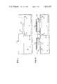
- FIGS. 1-11are cross-sectional views illustrating various process steps of the present invention for forming a CMOS device with polysilicon gates of a single conductivity and single impurity type.
- FIGS. 1-11wherein the successive steps of the fabrication process of the present invention are illustrated in detail.
- the steps to be discussed hereafterare illustrative of one technique for implementing the process of the subject invention. It will be obvious to those skilled in the micro-electronics art that the specific processes for implementing the various steps may be carried out in a number of different ways.
- n-FET'sshould be located in p-wells formed on an n-type substrate, or p-FET's located in n-wells formed on a p-type substrate, or each type of transistor located in its corresponding well formed on an n-type or p-type substrate.
- the substrate 10 shown in FIG. 1is n-type silicon upon which a p-well 15 is formed.
- the surface of substrate 10is first cleaned and then oxidized, for example, by placing in a high temperature (1,000° C.) steam oxidation furnace, forming a relatively thick (of the order of 6500 Angstroms) silicon oxide 11.
- a p-well opening 12is etched in the oxide 11 using conventional photolithography and buffered hydrofluoric acid etching. Then, a relatively thin (e.g., 900 Angstroms) layer of silicon oxide 13 is thermally grown in the opening 12. During this oxide 13 growing step, little or no oxidation takes place in the remainder of the substrate since the oxidation thereover is diffusion limited by the thick oxide 11. Also, during this process step the silicon substrate in the opening 12 is consumed to a depth equal to approximately one-half of the oxide 13 thickness (i.e., 450 Angstroms, in the above example) due to the well-accepted fact that the thickness of the oxide grown from silicon is approximately twice that of the silicon consumed.
- a topographical step 14--14(of an approximate 450 Angstroms height) is formed in the substrate, as shown in FIG. 1. This topographical step will be useful for aligning purposes at a later stage of the present process, as explained hereinbelow.
- the p-well 15is then formed by implanting p-type ions (such as boron) into the substrate 10 through the opening 12.
- p-type ionssuch as boron
- the energy of the ionsis so chosen as to penetrate the thin oxide layer 13, but not the thick oxide layer 11, thereby doping only the p-well 15.
- boron ionstypically, boron ions of energy 60 keV and dose 4 ⁇ 10 12 ions per square centimeter is used.
- the structureis then subjected to a long, high temperature diffusion cycle.
- An exemplary procedureis to introduce the structure in a furnace having a gaseous nitrogen atmosphere at a temperature of 1200° C. for about 24 hours. After the completion of this step, the boron ions diffuse laterally and downward to a distance of about 6 microns.
- the oxide layers 11 and 13are removed by using a conventional etching technique.
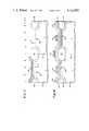
- the next step of the processinvolves formation of channel stops which define the active region of the p-FET and n-FET to be formed subsequently.
- an oxide layer 16hereinafter called support oxide
- the support oxide 16prevents damage to the silicon substrate 10 caused by stresses which would be created on the substrate by a silicon nitride 17-silicon 10 interface. Such stresses induce dislocations in the silicon substrate 10 which result in undesirable leakage current channels and otherwise have a deleterious effect on the electrical characteristics of the interface.
- a typical thickness of the support oxideis about 550 Angstroms.
- a pair of oxidation and implantation masksare formed over the support oxide 16.
- nitride layer 17is formed on the support oxide 16
- oxide layer 18is formed on the nitride 17.
- the thicknesses of the nitride 17 and oxide 18are typically in the range of (500-600) Angstroms and (1100-1300) Angstroms, respectively.
- the layers 17 and 18are then patterned in a conventional manner using a photoresist 19 and then etched to form the dual-layer masks 20 and 21 which delineate the n-FET and p-FET active regions respectively.
- the topographical steps 14--14 in the p-well 15 discussed in connection with FIG. 1are used to visually align the mask used to define the photoresist 19 over the dual mask 21. As shown in FIG. 3, the active regions are covered by the masks 20 and 21, whereas the field regions are covered only by support oxide 16.
- the channel stopsare then formed by doping the field regions which are potential sites of parasitic devices.
- CMOS devicemetallized interconnect lines are formed over the field oxide.
- the field regionsare doped, raising the threshold voltage of these regions to a level higher than the voltage that may be applied to the metallized lines.
- This field dopingconsists, in an exemplary process, of doping the p-well field regions 22--22 with p-type impurities and the n-substrate field regions 23--23 with n-type impurities.
- a photoresist layer 24is applied over the mask 20 and the n-substrate field regions 23--23 as shown in FIG. 3. Then, p-type ions, such as boron, are implanted in the p-well field regions 22--22 through the exposed support oxide 16. During this implantation step, the photoresist 24 protects the n-substrate field regions 23--23 and the p-FET active regions from doping and the mask 21 protects the n-FET active region from doping. The photoresist mask 24 is then removed.
- the n-substrate field regions 23--23are doped by forming a photoresist layer 25 over the mask 21 and the p-well field regions 22--22 and implanting with n-type ions, such as phosphorus, in a manner analogous to the previous step.
- the photoresist mask 25is then removed.
- the field (isolation) oxide 26 of thickness in the range 6,000-10,000 Angstromsis grown, for example by wet oxidation at a temperature of about 1,000° C.
- the nitride layer 17 of masks 20 and 21acts as a barrier to diffusion of oxygen species, thereby preventing growth of oxide in the n-FET and p-FET active regions.
- the oxide mask 18, the nitride mask 17 and the support oxide 16are then removed using conventional etching techniques. During this etching process, the thick field oxide regions 26 may be thinned somewhat, but not to a degree that their dielectric function is hampered. The bare active areas are now re-oxidized to form the gate oxide 27 of thickness in the range (300-1,000) Angstroms.
- the support oxide 16(FIG. 5) may be left in place and used as the gate oxide.
- a preferred procedureis to remove the oxide 16 (FIG. 5) and form a new oxide 27 (FIG. 6) in its place since this procedure permits a better control of the gate oxide thickness and also eliminates any possible contamination of the gate oxide which might take place as in the case of support oxide 16 during the deposition and subsequent etching of nitride 17, etc.
- the device active regionsare subjected to one or two ion implantations (of the same or opposite impurity type) to adjust the threshold voltages of p-FET's and n-FET's to the desired value. If two implantations of opposite impurity type are used, two photoresist masks may have to be used to alternately mask and implant the p-FET and n-FET active areas. In the present exemplary process two ion implantations of the same conductivity type are accomplished.
- the type of implantation species, their energy, and doseis a function of several factors including the resistivity or doping level of the starting material, the doping level of the p-well 15, the gate oxide 27 thickness, the type of polysilicon gate (to be formed later) and the actual threshold voltages desired.
- the substrate 10is n-type having a ⁇ 100> crystal orientation and bulk resistivity of about (3-6) ohm-centimeter
- the p-well 15 sheet resistanceis about 7,000 ohms per square
- the gate oxide 27 thicknessis about 600 Angstroms
- the polysilicon gates (to be formed)are n + -type
- the desired n-FET and p-FET threshold voltagesare +1 volt and -1 volt, respectively
- the two implantationscan be accomplished using boron ions of different doses.
- boron of dose 1.6 ⁇ 10 11 ions per square centimeter and energy 40 keVis implanted into the entire structure.
- the boron ionspenetrate through the thin gate oxide 27 and are lodged in the p-FET and n-FET active regions forming the surface charge layers 28 and 29, respectively.
- the p-FET threshold voltagewill be about -1 volt.
- the p-FET active regionis protected using a photoresist mask 30 and the exposed n-FET active area is implanted using boron ions of a higher dose, 3.9 ⁇ 10 11 ions per square centimeter, and the same energy (of 40 keV) as before.
- this combination of implantation stepssets the n-FET threshold voltage at about +1 volt, thereby matching it with the p-FET threshold voltage.
- the photoresist 30is then removed.
- a polysilicon layer 31is formed on the semiconductor structure to a typical thickness of about 5000 Angstroms by, for example, chemical vapor deposition at atmospheric or low pressure of (0.3-1) millitorr.
- the polysilicon 31is doped heavily using, for example, an n-type dopant.
- An exemplary process of doping the polysilicon 31utilizes a phosphorus pre-deposition and furnace diffusion steps. During this step, the back surface of the substrate 10 is also doped for insuring good back surface ohmic contact which will be beneficial during the packaging stage of the CMOS device, and also acting as a getter for metallic impurities.
- a layer of silicon oxide 32 of about 3500 Angstroms thicknessis formed by chemical vapor deposition on the polysilicon 31.
- the layer 32protects the underlying silicon 31 from additional doping during the later p-FET and n-FET source and drain implantation steps.
- the photoresist mask 33using a photoresist mask 33, the polysilicon gates and interconnecting conductor lines are defined by sequentially etching the oxide layer 32 and polysilicon 31 using buffered hydrofluoric acid and a plasma, respectively. The photoresist 33 is then removed. Two polysilicon gates 34, 35 and one polysilicon conductor line 36 formed in the manner just described are shown in FIG. 9.
- Gate 34is for the p-FET and gate 35 is for the n-FET.
- Conductor line 36is formed on the top of the central field isolation oxide 26. Note that the oxide layer 32A, 32B, and 32C over the gates 34 and 35 and the interconnecting line 36, respectively, is not removed.
- the next step of the process, shown in FIG. 9,is the formation of the source and drain for the n-FET.
- An exemplary technique for forming this step of the processinvolves depositing a layer of photoresist 37 on the semiconductor structure such that it uniformly covers the previously formed gate structures and conductor structures, then exposing and developing the photoresist to provide the photoresist mask 37 shown in FIG. 9.
- mask 37covers the p-FET active region, gate electrode 34 and conductor line 36.
- n-FET gate 35acts as a mask which serves to align the transistor's source 38 and drain 39 with the gate electrode 35.
- the energy of the n-type ionsare so chosen as to penetrate the thin oxide layer 27 over the source 39 and drain 40, but do not penetrate the relatively thick oxide 32B over the gate 35.
- the n-type ion doseis chosen sufficiently high to counterdope the p-type surface layer 29 in the source 38 and drain 39 areas that was introduced previously, and produce n + source 38 and drain 39.
- An exemplary set of implantation parameters for this stepis arsenic ions of dose 8 ⁇ 10 15 ions per square centimeter and energy 80 keV.
- the sheet resistance of the n + source 38 and drain 39 formed in this mannerwill be about 30 ohms per square.
- the photoresist 37is then removed.
- the source and drain regions of the p-FETare then formed in a manner analogous to the formation of n-FET source and drain.
- a photoresist mask 40is formed over the n-FET gate 35, source 38 and drain 39, and the conductor line 36.
- the p-FET gate electrode 34is not covered by mask 40 since the oxide layer 32A masks this electrode. Thus, only the p-FET active region is exposed.
- P-type ionsare then implanted to form the p + source 41 and drain 42 in a self-aligned relationship with the gate 34, in a manner fully analogous to the previous step in connection with the formation of the n-FET source 38 and drain 39.
- An exemplary set of implantation parameters to form the source 41 and drain 42is boron ions of dose 6 ⁇ 10 15 ions per square centimeter and energy 35 keV.
- the photoresist 40is then removed.
- the semiconductor structureis subjected to a high temperature anneal step to repair any damage to the silicon substrate lattice that may have been caused by the source and drain implants and to insure that the implanted ions are electrically activated.
- annealingis done at about 1000° C. in a gaseous nitrogen atmosphere. It is noted that no specific annealing was necessary after the earlier implantation steps of this process, such as the implantations to form the channel stops and adjust the devices threshold voltages because during subsequent high temperature process steps, such as oxidation steps and polysilicon 31 deposition step, impurity activation naturally takes place.
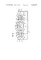
- FIG. 11is a cross-sectional representation of a completed CMOS device in accordance with the process of this invention
- the remaining steps of the processinclude: (1) formation of a thick (about 10,000 Angstroms) oxide 43 over the entire semiconductor structure to serve as an electrically insulating layer; (2) etching contact vias in oxide 43 corresponding to the sources 38 and 41, drains 39 and 42, gates 34 and 35 and interconnecting conductor 36; (3) depositing a conductive layer such as aluminum or aluminum-silicon alloy over the structure; (4) delineation of this conductive layer forming conductive contacts 44 and 45 for the polysilicon gates 34 and 35, respectively, conductive contact 46 for the interconnecting conductor 36, conductive contacts 47 and 48 for sources 38 and 41, respectively, contacts 49 and 50 for drains 39 and 42, respectively; and (5) forming a passivation layer 51 of a material such as phosphosilicate glass over the device.
Landscapes
- Physics & Mathematics (AREA)
- Engineering & Computer Science (AREA)
- High Energy & Nuclear Physics (AREA)
- General Physics & Mathematics (AREA)
- Toxicology (AREA)
- Condensed Matter Physics & Semiconductors (AREA)
- Health & Medical Sciences (AREA)
- Manufacturing & Machinery (AREA)
- Computer Hardware Design (AREA)
- Microelectronics & Electronic Packaging (AREA)
- Power Engineering (AREA)
- Metal-Oxide And Bipolar Metal-Oxide Semiconductor Integrated Circuits (AREA)
- Insulated Gate Type Field-Effect Transistor (AREA)
Abstract
Description
Claims (1)
Priority Applications (3)
| Application Number | Priority Date | Filing Date | Title |
|---|---|---|---|
| US06/332,037US4422885A (en) | 1981-12-18 | 1981-12-18 | Polysilicon-doped-first CMOS process |
| EP83900390AEP0097703A1 (en) | 1981-12-18 | 1982-12-14 | Process for forming a cmos integrated circuit structure |
| PCT/US1982/001762WO1983002197A1 (en) | 1981-12-18 | 1982-12-14 | Process for forming a cmos integrated circuit structure |
Applications Claiming Priority (1)
| Application Number | Priority Date | Filing Date | Title |
|---|---|---|---|
| US06/332,037US4422885A (en) | 1981-12-18 | 1981-12-18 | Polysilicon-doped-first CMOS process |
Publications (1)
| Publication Number | Publication Date |
|---|---|
| US4422885Atrue US4422885A (en) | 1983-12-27 |
Family
ID=23296446
Family Applications (1)
| Application Number | Title | Priority Date | Filing Date |
|---|---|---|---|
| US06/332,037Expired - LifetimeUS4422885A (en) | 1981-12-18 | 1981-12-18 | Polysilicon-doped-first CMOS process |
Country Status (3)
| Country | Link |
|---|---|
| US (1) | US4422885A (en) |
| EP (1) | EP0097703A1 (en) |
| WO (1) | WO1983002197A1 (en) |
Cited By (29)
| Publication number | Priority date | Publication date | Assignee | Title |
|---|---|---|---|---|
| US4462151A (en)* | 1982-12-03 | 1984-07-31 | International Business Machines Corporation | Method of making high density complementary transistors |
| US4516313A (en)* | 1983-05-27 | 1985-05-14 | Ncr Corporation | Unified CMOS/SNOS semiconductor fabrication process |
| US4555842A (en)* | 1984-03-19 | 1985-12-03 | At&T Bell Laboratories | Method of fabricating VLSI CMOS devices having complementary threshold voltages |
| US4596068A (en)* | 1983-12-28 | 1986-06-24 | Harris Corporation | Process for minimizing boron depletion in N-channel FET at the silicon-silicon oxide interface |
| US4621412A (en)* | 1984-09-17 | 1986-11-11 | Sony Corporation | Manufacturing a complementary MOSFET |
| US4646425A (en)* | 1984-12-10 | 1987-03-03 | Solid State Scientific, Inc. | Method for making a self-aligned CMOS EPROM wherein the EPROM floating gate and CMOS gates are made from one polysilicon layer |
| WO1987005443A1 (en)* | 1986-03-04 | 1987-09-11 | Motorola, Inc. | High/low doping profile for twin well process |
| US4701423A (en)* | 1985-12-20 | 1987-10-20 | Ncr Corporation | Totally self-aligned CMOS process |
| US4703552A (en)* | 1984-01-10 | 1987-11-03 | Sgs Microelettronica S.P.A. | Fabricating a CMOS transistor having low threshold voltages using self-aligned silicide polysilicon gates and silicide interconnect regions |
| US4722909A (en)* | 1985-09-26 | 1988-02-02 | Motorola, Inc. | Removable sidewall spacer for lightly doped drain formation using two mask levels |
| US4745086A (en)* | 1985-09-26 | 1988-05-17 | Motorola, Inc. | Removable sidewall spacer for lightly doped drain formation using one mask level and differential oxidation |
| US4760034A (en)* | 1987-06-15 | 1988-07-26 | Motorola, Inc. | Method of forming edge-sealed multi-layer structure while protecting adjacent region by screen oxide layer |
| US4889825A (en)* | 1986-03-04 | 1989-12-26 | Motorola, Inc. | High/low doping profile for twin well process |
| US5021356A (en)* | 1989-08-24 | 1991-06-04 | Delco Electronics Corporation | Method of making MOSFET depletion device |
| US5030582A (en)* | 1988-10-14 | 1991-07-09 | Matsushita Electric Industrial Co., Ltd. | Method of fabricating a CMOS semiconductor device |
| US5091332A (en)* | 1990-11-19 | 1992-02-25 | Intel Corporation | Semiconductor field oxidation process |
| US5273914A (en)* | 1988-10-14 | 1993-12-28 | Matsushita Electric Industrial Co., Ltd. | Method of fabricating a CMOS semiconductor devices |
| US5384279A (en)* | 1988-09-09 | 1995-01-24 | U.S. Philips Corporation | Method of manufacturing a semiconductor device comprising a silicon body in which semiconductor regions are formed by ion implantations |
| US5407849A (en)* | 1992-06-23 | 1995-04-18 | Imp, Inc. | CMOS process and circuit including zero threshold transistors |
| US5422301A (en)* | 1993-12-28 | 1995-06-06 | Fujitsu Limited | Method of manufacturing semiconductor device with MOSFET |
| US5650350A (en)* | 1995-08-11 | 1997-07-22 | Micron Technology, Inc. | Semiconductor processing method of forming a static random access memory cell and static random access memory cell |
| EP0771021A3 (en)* | 1990-06-26 | 1998-01-07 | AT&T Corp. | Transistor fabrication method |
| US5970334A (en)* | 1996-09-27 | 1999-10-19 | Nec Corporation | Method of manufacturing contacts to diverse doped regions using intermediate layer of arsenic or phosphorus |
| FR2818011A1 (en)* | 2000-11-21 | 2002-06-14 | Mitsubishi Electric Corp | ISOLATION FILM SEMICONDUCTOR DEVICE AND METHOD FOR MANUFACTURING THE SAME |
| US20020123179A1 (en)* | 1993-01-18 | 2002-09-05 | Semiconductor Energy Laboratory Co., Ltd. | MIS semiconductor device and method of fabricating the same |
| US20030153136A1 (en)* | 2002-02-14 | 2003-08-14 | Mitsubishi Denki Kabushiki Kaisha | Method of manufacturing semicontor device having trench isolation |
| US20060281239A1 (en)* | 2005-06-14 | 2006-12-14 | Suraj Mathew | CMOS fabrication |
| US20080293206A1 (en)* | 2007-05-25 | 2008-11-27 | Binghua Hu | Unique ldmos process integration |
| US10515801B2 (en) | 2007-06-04 | 2019-12-24 | Micron Technology, Inc. | Pitch multiplication using self-assembling materials |
Families Citing this family (5)
| Publication number | Priority date | Publication date | Assignee | Title |
|---|---|---|---|---|
| US4789883A (en)* | 1985-12-17 | 1988-12-06 | Advanced Micro Devices, Inc. | Integrated circuit structure having gate electrode and underlying oxide and method of making same |
| US4994402A (en)* | 1987-06-26 | 1991-02-19 | Hewlett-Packard Company | Method of fabricating a coplanar, self-aligned contact structure in a semiconductor device |
| EP0637074A3 (en)* | 1993-07-30 | 1995-06-21 | Sgs Thomson Microelectronics | Process for the formation of active and insulating domains by separate covering patterns. |
| US5679588A (en)* | 1995-10-05 | 1997-10-21 | Integrated Device Technology, Inc. | Method for fabricating P-wells and N-wells having optimized field and active regions |
| JP3621303B2 (en)* | 1999-08-30 | 2005-02-16 | Necエレクトロニクス株式会社 | Semiconductor device and manufacturing method thereof |
Citations (7)
| Publication number | Priority date | Publication date | Assignee | Title |
|---|---|---|---|---|
| US4224733A (en)* | 1977-10-11 | 1980-09-30 | Fujitsu Limited | Ion implantation method |
| US4277291A (en)* | 1979-01-22 | 1981-07-07 | Sgs-Ates Componenti Elettronici S.P.A. | Process for making CMOS field-effect transistors |
| US4280272A (en)* | 1977-07-04 | 1981-07-28 | Tokyo Shibaura Denki Kabushiki Kaisha | Method for preparing complementary semiconductor device |
| US4295897A (en)* | 1979-10-03 | 1981-10-20 | Texas Instruments Incorporated | Method of making CMOS integrated circuit device |
| US4306916A (en)* | 1979-09-20 | 1981-12-22 | American Microsystems, Inc. | CMOS P-Well selective implant method |
| US4314857A (en)* | 1979-07-31 | 1982-02-09 | Mitel Corporation | Method of making integrated CMOS and CTD by selective implantation |
| US4345366A (en)* | 1980-10-20 | 1982-08-24 | Ncr Corporation | Self-aligned all-n+ polysilicon CMOS process |
Family Cites Families (2)
| Publication number | Priority date | Publication date | Assignee | Title |
|---|---|---|---|---|
| US3999213A (en)* | 1972-04-14 | 1976-12-21 | U.S. Philips Corporation | Semiconductor device and method of manufacturing the device |
| US4033797A (en)* | 1973-05-21 | 1977-07-05 | Hughes Aircraft Company | Method of manufacturing a complementary metal-insulation-semiconductor circuit |
- 1981
- 1981-12-18USUS06/332,037patent/US4422885A/ennot_activeExpired - Lifetime
- 1982
- 1982-12-14WOPCT/US1982/001762patent/WO1983002197A1/ennot_activeApplication Discontinuation
- 1982-12-14EPEP83900390Apatent/EP0097703A1/ennot_activeWithdrawn
Patent Citations (8)
| Publication number | Priority date | Publication date | Assignee | Title |
|---|---|---|---|---|
| US4280272A (en)* | 1977-07-04 | 1981-07-28 | Tokyo Shibaura Denki Kabushiki Kaisha | Method for preparing complementary semiconductor device |
| US4224733A (en)* | 1977-10-11 | 1980-09-30 | Fujitsu Limited | Ion implantation method |
| US4277291A (en)* | 1979-01-22 | 1981-07-07 | Sgs-Ates Componenti Elettronici S.P.A. | Process for making CMOS field-effect transistors |
| US4314857A (en)* | 1979-07-31 | 1982-02-09 | Mitel Corporation | Method of making integrated CMOS and CTD by selective implantation |
| US4306916A (en)* | 1979-09-20 | 1981-12-22 | American Microsystems, Inc. | CMOS P-Well selective implant method |
| US4295897A (en)* | 1979-10-03 | 1981-10-20 | Texas Instruments Incorporated | Method of making CMOS integrated circuit device |
| US4295897B1 (en)* | 1979-10-03 | 1997-09-09 | Texas Instruments Inc | Method of making cmos integrated circuit device |
| US4345366A (en)* | 1980-10-20 | 1982-08-24 | Ncr Corporation | Self-aligned all-n+ polysilicon CMOS process |
Cited By (50)
| Publication number | Priority date | Publication date | Assignee | Title |
|---|---|---|---|---|
| US4462151A (en)* | 1982-12-03 | 1984-07-31 | International Business Machines Corporation | Method of making high density complementary transistors |
| US4516313A (en)* | 1983-05-27 | 1985-05-14 | Ncr Corporation | Unified CMOS/SNOS semiconductor fabrication process |
| US4596068A (en)* | 1983-12-28 | 1986-06-24 | Harris Corporation | Process for minimizing boron depletion in N-channel FET at the silicon-silicon oxide interface |
| US4703552A (en)* | 1984-01-10 | 1987-11-03 | Sgs Microelettronica S.P.A. | Fabricating a CMOS transistor having low threshold voltages using self-aligned silicide polysilicon gates and silicide interconnect regions |
| US4555842A (en)* | 1984-03-19 | 1985-12-03 | At&T Bell Laboratories | Method of fabricating VLSI CMOS devices having complementary threshold voltages |
| US4621412A (en)* | 1984-09-17 | 1986-11-11 | Sony Corporation | Manufacturing a complementary MOSFET |
| US4646425A (en)* | 1984-12-10 | 1987-03-03 | Solid State Scientific, Inc. | Method for making a self-aligned CMOS EPROM wherein the EPROM floating gate and CMOS gates are made from one polysilicon layer |
| US4745086A (en)* | 1985-09-26 | 1988-05-17 | Motorola, Inc. | Removable sidewall spacer for lightly doped drain formation using one mask level and differential oxidation |
| US4722909A (en)* | 1985-09-26 | 1988-02-02 | Motorola, Inc. | Removable sidewall spacer for lightly doped drain formation using two mask levels |
| US4701423A (en)* | 1985-12-20 | 1987-10-20 | Ncr Corporation | Totally self-aligned CMOS process |
| US4889825A (en)* | 1986-03-04 | 1989-12-26 | Motorola, Inc. | High/low doping profile for twin well process |
| WO1987005443A1 (en)* | 1986-03-04 | 1987-09-11 | Motorola, Inc. | High/low doping profile for twin well process |
| US4760034A (en)* | 1987-06-15 | 1988-07-26 | Motorola, Inc. | Method of forming edge-sealed multi-layer structure while protecting adjacent region by screen oxide layer |
| US5384279A (en)* | 1988-09-09 | 1995-01-24 | U.S. Philips Corporation | Method of manufacturing a semiconductor device comprising a silicon body in which semiconductor regions are formed by ion implantations |
| US5030582A (en)* | 1988-10-14 | 1991-07-09 | Matsushita Electric Industrial Co., Ltd. | Method of fabricating a CMOS semiconductor device |
| US5273914A (en)* | 1988-10-14 | 1993-12-28 | Matsushita Electric Industrial Co., Ltd. | Method of fabricating a CMOS semiconductor devices |
| US5021356A (en)* | 1989-08-24 | 1991-06-04 | Delco Electronics Corporation | Method of making MOSFET depletion device |
| EP0771021A3 (en)* | 1990-06-26 | 1998-01-07 | AT&T Corp. | Transistor fabrication method |
| US5091332A (en)* | 1990-11-19 | 1992-02-25 | Intel Corporation | Semiconductor field oxidation process |
| US5407849A (en)* | 1992-06-23 | 1995-04-18 | Imp, Inc. | CMOS process and circuit including zero threshold transistors |
| US20060128081A1 (en)* | 1993-01-18 | 2006-06-15 | Semiconductor Energy Laboratory Co., Ltd. | MIS semiconductor device and method of fabricating the same |
| US6984551B2 (en)* | 1993-01-18 | 2006-01-10 | Semiconductor Energy Laboratory Co., Ltd. | MIS semiconductor device and method of fabricating the same |
| US7351624B2 (en) | 1993-01-18 | 2008-04-01 | Semiconductor Energy Laboratory Co., Ltd. | MIS semiconductor device and method of fabricating the same |
| US20020123179A1 (en)* | 1993-01-18 | 2002-09-05 | Semiconductor Energy Laboratory Co., Ltd. | MIS semiconductor device and method of fabricating the same |
| US5422301A (en)* | 1993-12-28 | 1995-06-06 | Fujitsu Limited | Method of manufacturing semiconductor device with MOSFET |
| US5650350A (en)* | 1995-08-11 | 1997-07-22 | Micron Technology, Inc. | Semiconductor processing method of forming a static random access memory cell and static random access memory cell |
| US6117721A (en)* | 1995-08-11 | 2000-09-12 | Micron Technology, Inc. | Semiconductor processing method of forming a static random access memory cell and static random access memory cell |
| US5751046A (en)* | 1995-08-11 | 1998-05-12 | Micron Technology, Inc. | Semiconductor device with VT implant |
| US5739056A (en)* | 1995-08-11 | 1998-04-14 | Micron Technology, Inc. | Semiconductor processing method of forming a static random access memory cell and static random access memory cell |
| US5929495A (en)* | 1995-08-11 | 1999-07-27 | Micron Technology, Inc. | Semiconductor processing method of forming a static random access memory cell and static random access memory cell |
| US5970334A (en)* | 1996-09-27 | 1999-10-19 | Nec Corporation | Method of manufacturing contacts to diverse doped regions using intermediate layer of arsenic or phosphorus |
| FR2818011A1 (en)* | 2000-11-21 | 2002-06-14 | Mitsubishi Electric Corp | ISOLATION FILM SEMICONDUCTOR DEVICE AND METHOD FOR MANUFACTURING THE SAME |
| US20040046216A1 (en)* | 2000-11-21 | 2004-03-11 | Mitsubishi Denki Kabushiki Kaisha | Semiconductor device and method of manufacturing the same |
| US6914307B2 (en) | 2000-11-21 | 2005-07-05 | Mitsubishi Denki Kabushiki Kaisha | Semiconductor device and method of manufacturing the same |
| US20050212056A1 (en)* | 2000-11-21 | 2005-09-29 | Mitsubishi Denki Kabushiki Kaisha | Semiconductor device and method of manufacturing the same |
| FR2835966A1 (en)* | 2002-02-14 | 2003-08-15 | Mitsubishi Electric Corp | SEMICONDUCTOR DEVICE, MANUFACTURING METHOD, AND SEMICONDUCTOR WAFER |
| US20030153136A1 (en)* | 2002-02-14 | 2003-08-14 | Mitsubishi Denki Kabushiki Kaisha | Method of manufacturing semicontor device having trench isolation |
| US20060249756A1 (en)* | 2002-02-14 | 2006-11-09 | Renesas Technology Corp. | Method of manufacturing semiconductor device having trench isolation |
| US7144764B2 (en) | 2002-02-14 | 2006-12-05 | Renesas Technology Corp. | Method of manufacturing semiconductor device having trench isolation |
| US20050037524A1 (en)* | 2002-02-14 | 2005-02-17 | Renesas Technology Corp. | Method of manufacturing semiconductor device having trench isolation |
| US7858458B2 (en)* | 2005-06-14 | 2010-12-28 | Micron Technology, Inc. | CMOS fabrication |
| US20060281241A1 (en)* | 2005-06-14 | 2006-12-14 | Suraj Mathew | CMOS fabrication |
| US20060281239A1 (en)* | 2005-06-14 | 2006-12-14 | Suraj Mathew | CMOS fabrication |
| US8823108B2 (en) | 2005-06-14 | 2014-09-02 | Micron Technology, Inc. | CMOS fabrication |
| US9214394B2 (en) | 2005-06-14 | 2015-12-15 | Micron Technology, Inc. | CMOS fabrication |
| US9852953B2 (en) | 2005-06-14 | 2017-12-26 | Micron Technology, Inc. | CMOS fabrication |
| US20080293206A1 (en)* | 2007-05-25 | 2008-11-27 | Binghua Hu | Unique ldmos process integration |
| WO2008148090A1 (en)* | 2007-05-25 | 2008-12-04 | Texas Instruments Incorporated | Improved ldmos process integration |
| US7713825B2 (en) | 2007-05-25 | 2010-05-11 | Texas Instruments Incorporated | LDMOS transistor double diffused region formation process |
| US10515801B2 (en) | 2007-06-04 | 2019-12-24 | Micron Technology, Inc. | Pitch multiplication using self-assembling materials |
Also Published As
| Publication number | Publication date |
|---|---|
| WO1983002197A1 (en) | 1983-06-23 |
| EP0097703A1 (en) | 1984-01-11 |
Similar Documents
| Publication | Publication Date | Title |
|---|---|---|
| US4422885A (en) | Polysilicon-doped-first CMOS process | |
| US4078947A (en) | Method for forming a narrow channel length MOS field effect transistor | |
| US5047358A (en) | Process for forming high and low voltage CMOS transistors on a single integrated circuit chip | |
| US4819052A (en) | Merged bipolar/CMOS technology using electrically active trench | |
| US5326722A (en) | Polysilicon contact | |
| US4764480A (en) | Process for making high performance CMOS and bipolar integrated devices on one substrate with reduced cell size | |
| EP0138978B1 (en) | Method of manufacturing a semiconductor device having small dimensions | |
| US5573963A (en) | Method of forming self-aligned twin tub CMOS devices | |
| US4225877A (en) | Integrated circuit with C-Mos logic, and a bipolar driver with polysilicon resistors | |
| US4149307A (en) | Process for fabricating insulated-gate field-effect transistors with self-aligned contacts | |
| US4183134A (en) | High yield processing for silicon-on-sapphire CMOS integrated circuits | |
| KR900008207B1 (en) | Semiconductor memory device | |
| US4663825A (en) | Method of manufacturing semiconductor device | |
| US5294822A (en) | Polycide local interconnect method and structure | |
| US4235011A (en) | Semiconductor apparatus | |
| US5554554A (en) | Process for fabricating two loads having different resistance levels in a common layer of polysilicon | |
| US5047356A (en) | High speed silicon-on-insulator device and process of fabricating same | |
| EP0183623B1 (en) | Precision high-value mos capacitors | |
| US4797372A (en) | Method of making a merge bipolar and complementary metal oxide semiconductor transistor device | |
| US4637128A (en) | Method of producing semiconductor device | |
| US4507846A (en) | Method for making complementary MOS semiconductor devices | |
| US4462151A (en) | Method of making high density complementary transistors | |
| US4471523A (en) | Self-aligned field implant for oxide-isolated CMOS FET | |
| US4517731A (en) | Double polysilicon process for fabricating CMOS integrated circuits | |
| EP0337823A2 (en) | MOS field effect transistor having high breakdown voltage |
Legal Events
| Date | Code | Title | Description |
|---|---|---|---|
| AS | Assignment | Owner name:NCR CORPORATION, DAYTON, OH A CORP. OF MD Free format text:ASSIGNMENT OF ASSIGNORS INTEREST.;ASSIGNORS:BROWER, RONALD W.;CHIAO, SAMUEL Y.;PFEIFER, ROBERT F.;AND OTHERS;REEL/FRAME:003969/0606 Effective date:19811215 | |
| STCF | Information on status: patent grant | Free format text:PATENTED CASE | |
| MAFP | Maintenance fee payment | Free format text:PAYMENT OF MAINTENANCE FEE, 4TH YEAR, PL 96-517 (ORIGINAL EVENT CODE: M170); ENTITY STATUS OF PATENT OWNER: LARGE ENTITY Year of fee payment:4 | |
| MAFP | Maintenance fee payment | Free format text:PAYMENT OF MAINTENANCE FEE, 8TH YEAR, PL 96-517 (ORIGINAL EVENT CODE: M171); ENTITY STATUS OF PATENT OWNER: LARGE ENTITY Year of fee payment:8 | |
| AS | Assignment | Owner name:SAMSUNG ELECTRONICS CO., LTD., A CORP. OF REPUBLIC Free format text:ASSIGNMENT OF ASSIGNORS INTEREST.;ASSIGNOR:NCR CORPORATIONS, A CORP. OF MD;REEL/FRAME:005824/0788 Effective date:19910624 | |
| MAFP | Maintenance fee payment | Free format text:PAYMENT OF MAINTENANCE FEE, 12TH YEAR, LARGE ENTITY (ORIGINAL EVENT CODE: M185); ENTITY STATUS OF PATENT OWNER: LARGE ENTITY Year of fee payment:12 | |
| FEPP | Fee payment procedure | Free format text:PAYOR NUMBER ASSIGNED (ORIGINAL EVENT CODE: ASPN); ENTITY STATUS OF PATENT OWNER: LARGE ENTITY | |
| FEPP | Fee payment procedure | Free format text:PAYOR NUMBER ASSIGNED (ORIGINAL EVENT CODE: ASPN); ENTITY STATUS OF PATENT OWNER: LARGE ENTITY Free format text:PAYER NUMBER DE-ASSIGNED (ORIGINAL EVENT CODE: RMPN); ENTITY STATUS OF PATENT OWNER: LARGE ENTITY |