US4422451A - Spinal compression and distraction instrumentation - Google Patents
Spinal compression and distraction instrumentationDownload PDFInfo
- Publication number
- US4422451A US4422451AUS06/360,470US36047082AUS4422451AUS 4422451 AUS4422451 AUS 4422451AUS 36047082 AUS36047082 AUS 36047082AUS 4422451 AUS4422451 AUS 4422451A
- Authority
- US
- United States
- Prior art keywords
- hook
- spinal
- main body
- body section
- longitudinal passageway
- Prior art date
- Legal status (The legal status is an assumption and is not a legal conclusion. Google has not performed a legal analysis and makes no representation as to the accuracy of the status listed.)
- Expired - Fee Related
Links
- 230000006835compressionEffects0.000titleclaimsabstractdescription17
- 238000007906compressionMethods0.000titleclaimsabstractdescription17
- 238000007788rougheningMethods0.000description9
- 238000001356surgical procedureMethods0.000description7
- 239000000463materialSubstances0.000description3
- 206010058907Spinal deformityDiseases0.000description2
- 208000037873arthrodesisDiseases0.000description2
- 210000000988bone and boneAnatomy0.000description2
- 239000002184metalSubstances0.000description2
- 206010039722scoliosisDiseases0.000description2
- 208000000875Spinal CurvaturesDiseases0.000description1
- 230000000903blocking effectEffects0.000description1
- 230000000295complement effectEffects0.000description1
- 238000006073displacement reactionMethods0.000description1
- 239000007943implantSubstances0.000description1
- 238000000034methodMethods0.000description1
- 239000011505plasterSubstances0.000description1
- 230000002980postoperative effectEffects0.000description1
- 230000002265preventionEffects0.000description1
- 238000000926separation methodMethods0.000description1
- 206010041569spinal fractureDiseases0.000description1
- 229910001220stainless steelInorganic materials0.000description1
- 239000010935stainless steelSubstances0.000description1
- 238000010408sweepingMethods0.000description1
Images

Classifications
- A—HUMAN NECESSITIES
- A61—MEDICAL OR VETERINARY SCIENCE; HYGIENE
- A61B—DIAGNOSIS; SURGERY; IDENTIFICATION
- A61B17/00—Surgical instruments, devices or methods
- A61B17/56—Surgical instruments or methods for treatment of bones or joints; Devices specially adapted therefor
- A61B17/58—Surgical instruments or methods for treatment of bones or joints; Devices specially adapted therefor for osteosynthesis, e.g. bone plates, screws or setting implements
- A61B17/68—Internal fixation devices, including fasteners and spinal fixators, even if a part thereof projects from the skin
- A61B17/70—Spinal positioners or stabilisers, e.g. stabilisers comprising fluid filler in an implant
- A61B17/7001—Screws or hooks combined with longitudinal elements which do not contact vertebrae
- A61B17/7002—Longitudinal elements, e.g. rods
- A—HUMAN NECESSITIES
- A61—MEDICAL OR VETERINARY SCIENCE; HYGIENE
- A61B—DIAGNOSIS; SURGERY; IDENTIFICATION
- A61B17/00—Surgical instruments, devices or methods
- A61B17/56—Surgical instruments or methods for treatment of bones or joints; Devices specially adapted therefor
- A61B17/58—Surgical instruments or methods for treatment of bones or joints; Devices specially adapted therefor for osteosynthesis, e.g. bone plates, screws or setting implements
- A61B17/68—Internal fixation devices, including fasteners and spinal fixators, even if a part thereof projects from the skin
- A61B17/70—Spinal positioners or stabilisers, e.g. stabilisers comprising fluid filler in an implant
- A61B17/7074—Tools specially adapted for spinal fixation operations other than for bone removal or filler handling
- A61B17/7076—Tools specially adapted for spinal fixation operations other than for bone removal or filler handling for driving, positioning or assembling spinal clamps or bone anchors specially adapted for spinal fixation
- A—HUMAN NECESSITIES
- A61—MEDICAL OR VETERINARY SCIENCE; HYGIENE
- A61B—DIAGNOSIS; SURGERY; IDENTIFICATION
- A61B17/00—Surgical instruments, devices or methods
- A61B17/56—Surgical instruments or methods for treatment of bones or joints; Devices specially adapted therefor
- A61B17/58—Surgical instruments or methods for treatment of bones or joints; Devices specially adapted therefor for osteosynthesis, e.g. bone plates, screws or setting implements
- A61B17/68—Internal fixation devices, including fasteners and spinal fixators, even if a part thereof projects from the skin
- A61B17/70—Spinal positioners or stabilisers, e.g. stabilisers comprising fluid filler in an implant
- A61B17/7056—Hooks with specially-designed bone-contacting part
Definitions
- the present inventionrelates to instrumentation for spinal deformities and more particularly to spinal hooks, a support rod and locking structure for compressing and/or distracting the spine.
- Scoliosisis a lateral deviation of the spinal column.
- Such surgical treatmentis known as arthrodesis and consists of fusing together the vertebrae of the scoliotic curvature after correcting that curvature to the maximum possible extent. Correction can be accomplished prior to surgical treatment by continuous traction of the spine or by corrective plaster casts.
- a threaded support rod and hooksare placed on the spinal column for the purpose of straightening the spine and maintaining the correction until arthrodesis is accomplished by means of autogenous bone graft.
- the heretofore known implants used to correct curvature during surgeryinclude the Harrington system and the system disclosed in U.S. Pat. No. 4,269,178 to Keene, granted May 26, 1981.
- Each of the Harrington compression and distraction systemscomprises a threaded metal rod and a plurality of hooks having longitudinal passageways therein through which the rod extends.
- the hooksslide freely along the metal rod and each is adjusted by an internally threaded nut that mates with the rod. Appropriate placement of the hooks on the rod and tightening of the nut affects either compression of the convexity of scoliotic curvature or distraction of the concavity of such curvature.
- the individual hooksare positioned on the threaded rod by inserting either the top or bottom end of the rod into the longitudinal passageway extending through each of the hooks.
- Keene's U.S. Pat. No. 4,269,178is different from the Harrington system in that it allows special hooks to be tilted and manipulated into position between the vertebrae before the threaded rod engages the hooks.
- Each of the hooksincludes a slot in the rear surface thereof that communicates with the longitudinal passageway within which the threaded rod rests. While this arrangement allows easy placement of the hooks on the rod without threading them onto the rod from the rod ends, a sleeve interlock is required that prevents the threaded rod from being withdrawn out through the slotted opening in the rear surface of the hook.
- German Auslegeschrift No. 2,649,042discloses a similar interlock wherein bone screws are prevented from post-operative displacement from either rear or side slotted openings in the screw heads.
- an object of the present inventionis a spinal hook for positioning between the spinal vertebrae before engaging its associated support rod and without need for separate interlocking structure to prevent the hook and rod from separating.
- Another object of the present inventionis a hook holder which permits independent control and manipulation of each spinal hook.
- a hook for spinal compression and distraction instrumentationcomprises a main body section having a pair of opposite side surfaces, opposite top and bottom surfaces, and opposite front and rear surfaces.
- Hook structureis connected to and extends from the front surface of the main body section.
- a longitudinal passagewaycompletely extends through the main body section from the top surface thereof to the bottom surface thereof, the passageway including front and rear portions.
- a slotted opening in one of the side surfacesextends from the top surface of the main body section to the bottom surface thereof. The slotted opening communicates with the front portion of the longitudinal passageway and is positioned closer to the hook structure than the rear portion of the passageway.
- the hook structuremay open in an upward or downward direction. A portion of at least one of the side surfaces of the main body section may be roughened to facilitate handling.
- the spinal hook hereinis used in combination with a support rod adapted to be positioned within the longitudinal passageway at the rear portion thereof.
- the support rodhas a width slightly less than the width of the slotted opening, and locking structure is arranged to engage the rod and bear upon either the top or the bottom surface of the main body section.
- the rodis externally threaded and the locking structure is an internally threaded nut in meshing engagement with the rod.
- a hook holderpermits independent control of each hook during placement between the spinal vertebrae and also while the threaded support rod is advanced into the slotted opening in either side of the hook.
- the hook holdercomprises a pair of arms pivoted to one another at a point between the end portions thereof. One end portion of the arms forms a handle and the other end portion forms hook clamping structure including opposite undercut surfaces facing one another.
- the outer end of one of the arms forming the hook clamping structureis slightly longer than the outer end of the other arm and it has a longer undercut surface thereon. This arrangement enables the hook to be held without blocking the slotted opening.
- at least a portion of one of the undercut surfaces of the hook clamping structureis roughened to facilitate holding a hook.
- FIG. 1is a right side elevational view of spinal compression and distraction instrumentation, according to the present invention.
- FIG. 2is a right side elevational view of a spinal hook, according to the present invention.
- FIG. 3is a left side elevational view of the spinal hook shown in FIG. 2;
- FIG. 4is a top plan view of the spinal hook shown in FIG. 2;
- FIG. 5is a bottom plan view of the spinal hook shown in FIG. 2;
- FIG. 6is a cross-sectional view taken along line 6--6 of FIG. 1;
- FIG. 7is a bottom plan view of an alternate embodiment of spinal hook, according to the present invention.
- FIG. 8is a bottom plan view of a further embodiment of spinal hook, according to the present invention.
- FIG. 9is a side elevational view of a hook holder with a spinal hook clamped therein shown in phantom outline;
- FIG. 10is a cross-sectional view taken along line 9--9 of FIG. 9 with the spinal hook shown in elevation;
- FIG. 11is a fragmental cross-sectional view through the hook clamping end of the holder shown in FIG. 9;
- FIG. 12is a pictorial diagrammatic view illustrating the spinal hooks positioned between the vertebrae for compression and distraction of the spine.
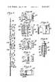
- FIG. 1illustrates spinal compression and distraction instrumentation 10 for use in correcting spinal deformities, as explained more fully below.
- the instrumentation 10comprises a plurality of spinal hooks 12,14, a threaded flexible support rod 16, and locking nuts 18, one nut being associated with each spinal hook.
- the spinal hooks, support rod, and locking nutsmay be formed from stainless steel or other suitable material.
- FIGS. 2-5illustrate a spinal hook 12 comprising a main body section 20 having a pair of opposite side surfaces 22,24.
- the main body section 20 of the spinal hookhas opposite top and bottom surfaces 26 and 28, respectively, and opposite front and rear surfaces 30, 32, respectively.
- a hook portion 34is connected to and extends from the front surface 30.
- a longitudinal passageway 36completely extends through the main body section from the top surface 26 thereof to the bottom surface 28.
- the longitudinal passagewayincludes front and rear portions 38 and 40, respectively, and a slotted opening 42 in the side surface 24 communicates with the front portion 38 of the passageway.
- the slotted opening 42is positioned in the side wall 24 so that it is closer to the hook portion 34 than the rear portion 40 of the passageway 36.
- the spinal hook 14 shown in FIG. 1is identical to the hook 12 in all respects except that the slotted opening is located in the opposite side wall surface 22. Accordingly, similar reference numerals are used in connection with spinal hook 14, it being understood that the slotted opening 42A is located in side wall 22 whereas the slotted opening 42 of hook 12 is located in the opposite side wall 24.
- spinal hooks 12,14may be positioned on the threaded support rod 16 with the hook portion 34 thereof upwardly or downwardly open.
- the slotted opening 42is positioned on the right side of the instrumentation 10 shown in FIG. 1 as defined by the orientation of FIG. 12.
- the slotted opening 42Ais on the left side of the instrumentation.
- the slotted opening 42 of hook 12is located on the left side of the instrumentation while opening 42A of hook 14 is positioned on the right side thereof.
- the longitudinal passageway 36 which extends through each spinal hookhas a substantially uniform cross-section along its length.
- the passageway 36is elongate and the major axis thereof is along a line that runs from the front surface 30 to the rear surface 32 of the main body section 20.
- FIG. 7illustrates a slightly modified embodiment having a different longitudinal passageway 36A. Otherwise the spinal hook shown in FIG. 7 is identical to the structure of FIGS. 2-5. While the cross-section of the longitudinal passageway 36A is elongate, the major axis of that elongate cross-section is angled with respect to the line that runs from the front surface 30 of the rear surface 32 of the main body section 20. This angled configuration functions to guide the support rod 6 to the rear portion 40 of the passageway 36 after the rod engages the passageway from the slotted opening 42.
- FIG. 8illustrates a further embodiment having a longitudinal passageway 36B different from the passageways 36 and 36A. Otherwise, the spinal hook shown in FIG. 7 is substantially identical to the structure of FIGS. 2-5 and FIG. 7.
- the cross-section of the longitudinal passageway 36Bprovides a sweeping curve for guiding the support rod 6 into the passageway to the rear portion thereof.
- Spinal hooks 12 and 14may further include a roughened area 44 on at least a portion of one of the opposite side surfaces 22,24 of the main body section 20.
- the rougheningmay be in the form of crisscrosses or vertical serrations, and such roughening may be located on the side surface adjacent to the slotted opening.
- spinal hook 12the roughening is on the side surface 24 adjacent slotted opening 42
- spinal hook 14the roughening is on side surface 22 adjacent slotted opening 42A.
- a central hole 46is provided in the side surface of the spinal hook opposite the slotted opening.
- the roughening 44 and central hole 46cooperate with complementary structure on a hook holder designed to clamp onto the hook and assist in controlling and manipulating the hook into position on the spine.
- a hook holder 50 according to the present inventionis illustrated in FIGS. 9-11 of the drawing.
- the holderincludes a pair of arms 52,54 pivoted to one another at a point 56 between the end portions thereof.
- One end portion of the arms 52,54forms a handle 58 while the other end portion forms hook clamping structure 60.
- the hook clamping structure of the holder 50includes opposite undercut surfaces 62,64 facing one another, as shown best in FIGS. 9 and 11.
- the undercut surface 64is longer than the undercut surface 62 and includes a central projection 66 extending therefrom.
- the spinal hookis positioned between the clamping structure 60 of the holder so that the central projection 66 on the longer undercut surface 64 is positioned within the central hole 46 in the side surface of the spinal hook.
- the shorter undercut surface 62may be roughened at 68 in such a manner that it mates with the roughening on the side surface of the spinal hook opposite the one in which the hole 46 is located.
- the rear surface 32 of the spinal hooksnugly engages the hook holder precisely at the beginning of the undercut surfaces 62,64 which prevents the hook from moving relative to the holder once it is clamped therein.
- the spinal compression and distraction instrumentation 10 of the present inventionis utilized for surgical treatment of spinal fractures or for straightening of the spine in the surgical treatment for deviations of the spinal column, especially scoliosis.
- Appropriate placement of the spinal hooks between the vertebraeis used to compress the convexity of scoliotic curvature or distract the concavity of such curvature.
- both compression and distractionmay be accomplished at the same time at different locations along the spine.
- the upper two spinal hooks 12 on the threaded support rod 16face one another with the lower hook portion 34 upwardly open and the higher hook downwardly open.
- the upper two spinal hooksmove toward one another thereby placing in compression A any material between them. Compression A is also achieved between the lowermost pair of spinal hooks 14 on the support rod 16, and also when the middle spinal hook 12 is urged in a downward direction.
- Distraction Bis accomplished by urging a spinal hook away from an adjacent spinal hook, and such distraction B is illustrated in FIG. 1 between the third and fourth highest spinal hooks on the support rod. As is clear from the drawing, upon tightening of the locking nuts 18 these spinal hooks move away from one another, thereby placing in distraction B any material betweem them.
- the assembled spinal hooks 12,14, support rod 16, and locking nuts 18are arranged so that the support rod is seated at the rear portion 40 of the longitudinal passageway 36 of each spinal hook. Since the tendency of the rod is to move to the rear portion of the passageway when the locking nuts are tightened, such positioning prevents the hook and rod from separating. Also, to aid in the prevention of such separation, the slotted openings 42,42A of adjacent spinal hooks in the final assembly are located on opposite sides of that assembly. Every other spinal hook in the final assembly has a slotted opening on one side thereof while the other spinal hooks have their slotted openings on the opposite side of the assembly.
- spinal hooks 12,14are shown at appropriate locations along a spinal column 70 comprising individual vertebrae 72. Placement of the spinal hooks is accomplished by initially clamping a hook between the undercut clamping surfaces 62,64 of the hook holder 50. The projection 66 on the hook holder engages the hole 46 in the spinal hook. Additionally when the roughening feature is incorporated, the roughening on undercut surfaces 62 of the holder engages the roughening 44 on the side surface of the spinal hook. The holder is then used to position the spinal hook at the purchase site around the transverse process or vertebrae 72. The hook holder and hook remain at that position on the spine until the other spinal hooks in the column have been similarly positioned, and the support rod manipulated to interconnect the hooks. Alternatively, a sharp spinal hook may be used first to form the purchase sites after which the spinal hooks 12,14 are positioned at those sites with the aid of the hook holders.
- the threaded support rod 16 and locking nuts 18are brought into engagement with the hooks.
- the rod 16is urged into the left side slotted opening 42 of the lowermost spinal hook 12 and is ultimately positioned at the rear portion 40 of the passageway 36.
- a locking nut 18is positioned to bear upon the top surface 22 of the inverted spinal hook 12.
- the support rodis urged into the right side slotted opening 42 of the next spinal hook in the assembly, and a locking nut 18 is arranged on the support rod 16 so that it bears upon the top surface 26 of that upright hook.
- Appropriate tightening of the locking nuts 18advances the pair of lowermost spinal hooks toward one another thereby applying compression A to the spinal vertebrae located between these hooks.
- the support rodengages the other spinal hooks in the assembly in similar fashion, and the locking nuts 18 are tightened to achieve either compression A or distraction B.
- the hook holdersmay be removed after the locking nuts are tightened.
- the particular spinal hooks 12,14are selected so that adjacent spinal hooks have their slotted openings on opposite sides.
- FIG. 12also illustrates a second assembly of spinal hooks 12 arranged between the vertebrae 72 at the left side of the spinal column in order to achieve compression A at those areas where distraction B is accomplished on the right side of the spine.
Landscapes
- Health & Medical Sciences (AREA)
- Orthopedic Medicine & Surgery (AREA)
- Neurology (AREA)
- Life Sciences & Earth Sciences (AREA)
- Surgery (AREA)
- Heart & Thoracic Surgery (AREA)
- Engineering & Computer Science (AREA)
- Biomedical Technology (AREA)
- Nuclear Medicine, Radiotherapy & Molecular Imaging (AREA)
- Medical Informatics (AREA)
- Molecular Biology (AREA)
- Animal Behavior & Ethology (AREA)
- General Health & Medical Sciences (AREA)
- Public Health (AREA)
- Veterinary Medicine (AREA)
- Surgical Instruments (AREA)
- Prostheses (AREA)
Abstract
Description
The present invention relates to instrumentation for spinal deformities and more particularly to spinal hooks, a support rod and locking structure for compressing and/or distracting the spine.
Scoliosis is a lateral deviation of the spinal column. When the spinal curvature exceeds a given limit it becomes necessary to consider surgical treatment. Such surgical treatment is known as arthrodesis and consists of fusing together the vertebrae of the scoliotic curvature after correcting that curvature to the maximum possible extent. Correction can be accomplished prior to surgical treatment by continuous traction of the spine or by corrective plaster casts.
During surgery the correction is completed and finalized. For this purpose, a threaded support rod and hooks are placed on the spinal column for the purpose of straightening the spine and maintaining the correction until arthrodesis is accomplished by means of autogenous bone graft. The heretofore known implants used to correct curvature during surgery include the Harrington system and the system disclosed in U.S. Pat. No. 4,269,178 to Keene, granted May 26, 1981.
Each of the Harrington compression and distraction systems comprises a threaded metal rod and a plurality of hooks having longitudinal passageways therein through which the rod extends. The hooks slide freely along the metal rod and each is adjusted by an internally threaded nut that mates with the rod. Appropriate placement of the hooks on the rod and tightening of the nut affects either compression of the convexity of scoliotic curvature or distraction of the concavity of such curvature. In the Harrington system, the individual hooks are positioned on the threaded rod by inserting either the top or bottom end of the rod into the longitudinal passageway extending through each of the hooks.
The system disclosed in Keene's U.S. Pat. No. 4,269,178 is different from the Harrington system in that it allows special hooks to be tilted and manipulated into position between the vertebrae before the threaded rod engages the hooks. Each of the hooks includes a slot in the rear surface thereof that communicates with the longitudinal passageway within which the threaded rod rests. While this arrangement allows easy placement of the hooks on the rod without threading them onto the rod from the rod ends, a sleeve interlock is required that prevents the threaded rod from being withdrawn out through the slotted opening in the rear surface of the hook. German Auslegeschrift No. 2,649,042 discloses a similar interlock wherein bone screws are prevented from post-operative displacement from either rear or side slotted openings in the screw heads.
Accordingly, an object of the present invention is a spinal hook for positioning between the spinal vertebrae before engaging its associated support rod and without need for separate interlocking structure to prevent the hook and rod from separating.
Another object of the present invention is a hook holder which permits independent control and manipulation of each spinal hook.
In accordance with the present invention, a hook for spinal compression and distraction instrumentation comprises a main body section having a pair of opposite side surfaces, opposite top and bottom surfaces, and opposite front and rear surfaces. Hook structure is connected to and extends from the front surface of the main body section. A longitudinal passageway completely extends through the main body section from the top surface thereof to the bottom surface thereof, the passageway including front and rear portions. A slotted opening in one of the side surfaces extends from the top surface of the main body section to the bottom surface thereof. The slotted opening communicates with the front portion of the longitudinal passageway and is positioned closer to the hook structure than the rear portion of the passageway.
The hook structure may open in an upward or downward direction. A portion of at least one of the side surfaces of the main body section may be roughened to facilitate handling.
The spinal hook herein is used in combination with a support rod adapted to be positioned within the longitudinal passageway at the rear portion thereof. The support rod has a width slightly less than the width of the slotted opening, and locking structure is arranged to engage the rod and bear upon either the top or the bottom surface of the main body section. Preferably, the rod is externally threaded and the locking structure is an internally threaded nut in meshing engagement with the rod.
A hook holder permits independent control of each hook during placement between the spinal vertebrae and also while the threaded support rod is advanced into the slotted opening in either side of the hook. The hook holder comprises a pair of arms pivoted to one another at a point between the end portions thereof. One end portion of the arms forms a handle and the other end portion forms hook clamping structure including opposite undercut surfaces facing one another. The outer end of one of the arms forming the hook clamping structure is slightly longer than the outer end of the other arm and it has a longer undercut surface thereon. This arrangement enables the hook to be held without blocking the slotted opening. Preferably, at least a portion of one of the undercut surfaces of the hook clamping structure is roughened to facilitate holding a hook.
Novel features and advantages of the present invention in addition to those noted above will become apparent to those skilled in the art from a reading of the following detailed description in conjunction with the accompanying drawing wherein:
FIG. 1 is a right side elevational view of spinal compression and distraction instrumentation, according to the present invention;
FIG. 2 is a right side elevational view of a spinal hook, according to the present invention;
FIG. 3 is a left side elevational view of the spinal hook shown in FIG. 2;
FIG. 4 is a top plan view of the spinal hook shown in FIG. 2;
FIG. 5 is a bottom plan view of the spinal hook shown in FIG. 2;
FIG. 6 is a cross-sectional view taken alongline 6--6 of FIG. 1;
FIG. 7 is a bottom plan view of an alternate embodiment of spinal hook, according to the present invention;
FIG. 8 is a bottom plan view of a further embodiment of spinal hook, according to the present invention;
FIG. 9 is a side elevational view of a hook holder with a spinal hook clamped therein shown in phantom outline;
FIG. 10 is a cross-sectional view taken alongline 9--9 of FIG. 9 with the spinal hook shown in elevation;
FIG. 11 is a fragmental cross-sectional view through the hook clamping end of the holder shown in FIG. 9; and
FIG. 12 is a pictorial diagrammatic view illustrating the spinal hooks positioned between the vertebrae for compression and distraction of the spine.
Referring in more particularity to the drawing, FIG. 1 illustrates spinal compression anddistraction instrumentation 10 for use in correcting spinal deformities, as explained more fully below. Theinstrumentation 10 comprises a plurality ofspinal hooks flexible support rod 16, andlocking nuts 18, one nut being associated with each spinal hook. The spinal hooks, support rod, and locking nuts may be formed from stainless steel or other suitable material.
FIGS. 2-5 illustrate aspinal hook 12 comprising amain body section 20 having a pair ofopposite side surfaces main body section 20 of the spinal hook has opposite top andbottom surfaces rear surfaces hook portion 34 is connected to and extends from thefront surface 30. As shown best in FIGS. 4 and 5, alongitudinal passageway 36 completely extends through the main body section from thetop surface 26 thereof to thebottom surface 28. The longitudinal passageway includes front andrear portions slotted opening 42 in theside surface 24 communicates with thefront portion 38 of the passageway. Theslotted opening 42 is positioned in theside wall 24 so that it is closer to thehook portion 34 than therear portion 40 of thepassageway 36.
Thespinal hook 14 shown in FIG. 1 is identical to thehook 12 in all respects except that the slotted opening is located in the oppositeside wall surface 22. Accordingly, similar reference numerals are used in connection withspinal hook 14, it being understood that theslotted opening 42A is located inside wall 22 whereas theslotted opening 42 ofhook 12 is located in theopposite side wall 24.
As is readily apparent from FIG. 1 and the pictorial view of FIG. 12,spinal hooks support rod 16 with thehook portion 34 thereof upwardly or downwardly open. For example, when thehook portion 34 ofspinal hook 12 is downwardly open, the slottedopening 42 is positioned on the right side of theinstrumentation 10 shown in FIG. 1 as defined by the orientation of FIG. 12. On the other hand, when thehook portion 34 ofspinal hook 14 is downwardly open, the slottedopening 42A is on the left side of the instrumentation. Conversely, when thehook portion 34 of the spinal hooks 12,14 is upwardly open, the slotted opening 42 ofhook 12 is located on the left side of the instrumentation while opening 42A ofhook 14 is positioned on the right side thereof.
Thelongitudinal passageway 36 which extends through each spinal hook has a substantially uniform cross-section along its length. In the embodiment of the invention shown in FIG. 5, thepassageway 36 is elongate and the major axis thereof is along a line that runs from thefront surface 30 to therear surface 32 of themain body section 20. FIG. 7 illustrates a slightly modified embodiment having a differentlongitudinal passageway 36A. Otherwise the spinal hook shown in FIG. 7 is identical to the structure of FIGS. 2-5. While the cross-section of thelongitudinal passageway 36A is elongate, the major axis of that elongate cross-section is angled with respect to the line that runs from thefront surface 30 of therear surface 32 of themain body section 20. This angled configuration functions to guide thesupport rod 6 to therear portion 40 of thepassageway 36 after the rod engages the passageway from the slottedopening 42.
FIG. 8 illustrates a further embodiment having alongitudinal passageway 36B different from thepassageways longitudinal passageway 36B provides a sweeping curve for guiding thesupport rod 6 into the passageway to the rear portion thereof.
Spinal hooks 12 and 14 may further include a roughenedarea 44 on at least a portion of one of the opposite side surfaces 22,24 of themain body section 20. Preferably, the roughening may be in the form of crisscrosses or vertical serrations, and such roughening may be located on the side surface adjacent to the slotted opening. Withspinal hook 12, the roughening is on theside surface 24 adjacent slottedopening 42, and withspinal hook 14, the roughening is onside surface 22 adjacent slottedopening 42A. Also, in the side surface of the spinal hook opposite the slotted opening, acentral hole 46 is provided. As explained more fully below, the roughening 44 andcentral hole 46 cooperate with complementary structure on a hook holder designed to clamp onto the hook and assist in controlling and manipulating the hook into position on the spine.
Ahook holder 50 according to the present invention is illustrated in FIGS. 9-11 of the drawing. The holder includes a pair ofarms point 56 between the end portions thereof. One end portion of thearms handle 58 while the other end portion formshook clamping structure 60. The hook clamping structure of theholder 50 includes opposite undercutsurfaces surface 64 is longer than the undercutsurface 62 and includes acentral projection 66 extending therefrom. The spinal hook is positioned between the clampingstructure 60 of the holder so that thecentral projection 66 on the longer undercutsurface 64 is positioned within thecentral hole 46 in the side surface of the spinal hook. Moreover, the shorter undercutsurface 62 may be roughened at 68 in such a manner that it mates with the roughening on the side surface of the spinal hook opposite the one in which thehole 46 is located. Also important is the fact that therear surface 32 of the spinal hook snugly engages the hook holder precisely at the beginning of the undercut surfaces 62,64 which prevents the hook from moving relative to the holder once it is clamped therein.
The spinal compression anddistraction instrumentation 10 of the present invention is utilized for surgical treatment of spinal fractures or for straightening of the spine in the surgical treatment for deviations of the spinal column, especially scoliosis. Appropriate placement of the spinal hooks between the vertebrae is used to compress the convexity of scoliotic curvature or distract the concavity of such curvature. Alternatively, both compression and distraction may be accomplished at the same time at different locations along the spine.
Referring first to FIG. 1, the upper twospinal hooks 12 on the threadedsupport rod 16 face one another with thelower hook portion 34 upwardly open and the higher hook downwardly open. When the lockingnuts 18 are positioned as shown and tightened, the upper two spinal hooks move toward one another thereby placing in compression A any material between them. Compression A is also achieved between the lowermost pair ofspinal hooks 14 on thesupport rod 16, and also when the middlespinal hook 12 is urged in a downward direction.
Distraction B is accomplished by urging a spinal hook away from an adjacent spinal hook, and such distraction B is illustrated in FIG. 1 between the third and fourth highest spinal hooks on the support rod. As is clear from the drawing, upon tightening of the lockingnuts 18 these spinal hooks move away from one another, thereby placing in distraction B any material betweem them.
The assembledspinal hooks support rod 16, and lockingnuts 18 are arranged so that the support rod is seated at therear portion 40 of thelongitudinal passageway 36 of each spinal hook. Since the tendency of the rod is to move to the rear portion of the passageway when the locking nuts are tightened, such positioning prevents the hook and rod from separating. Also, to aid in the prevention of such separation, the slottedopenings
Turning now to FIG. 12, spinal hooks 12,14 are shown at appropriate locations along aspinal column 70 comprisingindividual vertebrae 72. Placement of the spinal hooks is accomplished by initially clamping a hook between the undercut clamping surfaces 62,64 of thehook holder 50. Theprojection 66 on the hook holder engages thehole 46 in the spinal hook. Additionally when the roughening feature is incorporated, the roughening on undercutsurfaces 62 of the holder engages the roughening 44 on the side surface of the spinal hook. The holder is then used to position the spinal hook at the purchase site around the transverse process orvertebrae 72. The hook holder and hook remain at that position on the spine until the other spinal hooks in the column have been similarly positioned, and the support rod manipulated to interconnect the hooks. Alternatively, a sharp spinal hook may be used first to form the purchase sites after which the spinal hooks 12,14 are positioned at those sites with the aid of the hook holders.
Once the spinal hooks are appropriately positioned on the right side of the spinal column as shown in FIG. 12, it being understood that a hook holder is associated with each of them, the threadedsupport rod 16 and lockingnuts 18 are brought into engagement with the hooks. For example, therod 16 is urged into the left side slotted opening 42 of the lowermostspinal hook 12 and is ultimately positioned at therear portion 40 of thepassageway 36. A lockingnut 18 is positioned to bear upon thetop surface 22 of the invertedspinal hook 12. Similarly, the support rod is urged into the right side slotted opening 42 of the next spinal hook in the assembly, and a lockingnut 18 is arranged on thesupport rod 16 so that it bears upon thetop surface 26 of that upright hook. Appropriate tightening of the lockingnuts 18 advances the pair of lowermost spinal hooks toward one another thereby applying compression A to the spinal vertebrae located between these hooks. The support rod engages the other spinal hooks in the assembly in similar fashion, and the lockingnuts 18 are tightened to achieve either compression A or distraction B. The hook holders may be removed after the locking nuts are tightened.
Once it is determined where the compression and distraction is to be applied along thespinal column 70, the particular spinal hooks 12,14 are selected so that adjacent spinal hooks have their slotted openings on opposite sides. By positioning the support rod at therear portion 40 of the longitudinal passageway of each spinal hook and by having alternate side slotted openings, stability is achieved and the threaded support rod is prevented from being inadvertently or otherwise withdrawn from the spinal hooks.
FIG. 12 also illustrates a second assembly ofspinal hooks 12 arranged between thevertebrae 72 at the left side of the spinal column in order to achieve compression A at those areas where distraction B is accomplished on the right side of the spine.
Claims (15)
1. A hook for spinal compression and distraction instrumentation comprising a main body section having a pair of opposite side surfaces, opposite top and bottom surfaces, and opposite front and rear surfaces, hook means connected to and extending from the front surface of the main body section, a longitudinal passageway completely extending through the main body section from the top surface thereof to the bottom surface thereof, the longitudinal passageway including front and rear portions, and a slotted opening in one of the side surfaces extending from the top surface of the main body section to the bottom surface thereof, the slotted opening communicating with the front portion of the longitudinal passageway and positioned closer to the hook means than the rear portion of the longitudinal passageway.
2. A hook as in claim 1 wherein the hook means is upwardly open.
3. A hook as in claim 1 wherein the hook means is downwardly open.
4. A hook as in claim 1 wherein the longitudinal passageway has a substantially uniform cross-section throughout its length.
5. A hook as in claim 4 wherein the cross-section of the longitudinal passageway is elongate and the major axis of the elongate cross-section is along a line that runs from the front surface to the rear surface of the main body section.
6. A hook as in claim 4 wherein the cross-section of the longitudinal passageway is elongate and the major axis of the elongate cross-section is angled with respect to a line that runs from the front surface to the rear surface of the main body section.
7. A hook as in claim 1 wherein a portion of at least one of the opposite side surfaces of the main body section is roughened to facilitate handling.
8. A hook as in claim 1 wherein at least one of the opposite side surfaces of the main body section includes a central hole.
9. A hook as in claim 1 in combination with a support rod adapted to be positioned within the longitudinal passageway at the rear portion thereof, the support rod having a width slightly less than the width of the slotted opening, and locking means engaging the rod and arranged to bear upon either the top or bottom surface of the main body section.
10. The combination of claim 9 including a second hook on the support rod, the hooks having slotted openings on opposite sides.
11. The combination of claim 9 wherein the support rod is externally threaded and the locking means is an internally threaded nut in meshing engagement with the rod.
12. A hook holder comprising a pair of arms pivoted to one another at a point between the end portions thereof, one end portion of the arms forming handle means and the other end portion forming hook clamping means including opposite undercut surfaces facing one another, the outer end of one of the arms forming the hook clamping means being slightly longer than the outer end of the other arm and having a longer undercut surface thereon.
13. A hook holder as in claim 12 wherein at least a portion of one of the undercut surfaces of the hook clamping means is roughened to facilitate holding a hook.
14. A hook holder as in claim 12 wherein the longer undercut surface includes a central projection thereon.
15. A hook holder as in claim 14 in combination with a spinal hook having opposite side surfaces, and a central hole in one of the side surfaces constructed and arranged to receive the central projection on the longer undercut surface of the hook holder.
Priority Applications (1)
| Application Number | Priority Date | Filing Date | Title |
|---|---|---|---|
| US06/360,470US4422451A (en) | 1982-03-22 | 1982-03-22 | Spinal compression and distraction instrumentation |
Applications Claiming Priority (1)
| Application Number | Priority Date | Filing Date | Title |
|---|---|---|---|
| US06/360,470US4422451A (en) | 1982-03-22 | 1982-03-22 | Spinal compression and distraction instrumentation |
Publications (1)
| Publication Number | Publication Date |
|---|---|
| US4422451Atrue US4422451A (en) | 1983-12-27 |
Family
ID=23418089
Family Applications (1)
| Application Number | Title | Priority Date | Filing Date |
|---|---|---|---|
| US06/360,470Expired - Fee RelatedUS4422451A (en) | 1982-03-22 | 1982-03-22 | Spinal compression and distraction instrumentation |
Country Status (1)
| Country | Link |
|---|---|
| US (1) | US4422451A (en) |
Cited By (89)
| Publication number | Priority date | Publication date | Assignee | Title |
|---|---|---|---|---|
| US4636217A (en)* | 1985-04-23 | 1987-01-13 | Regents Of The University Of Minnesota | Anterior spinal implant |
| US4641636A (en)* | 1983-05-04 | 1987-02-10 | Cotrel Yves P C A | Device for supporting the rachis |
| USD291729S (en) | 1985-05-08 | 1987-09-01 | Zimmer, Inc. | Spinal hook distractor or the like |
| US4773402A (en)* | 1985-09-13 | 1988-09-27 | Isola Implants, Inc. | Dorsal transacral surgical implant |
| EP0284559A1 (en)* | 1987-03-19 | 1988-09-28 | Oscobal Ag | An implant for the operative correction of spinal deformity |
| US5007909A (en)* | 1986-11-05 | 1991-04-16 | Chaim Rogozinski | Apparatus for internally fixing the spine |
| US5010879A (en)* | 1989-03-31 | 1991-04-30 | Tanaka Medical Instrument Manufacturing Co. | Device for correcting spinal deformities |
| US5020519A (en)* | 1990-12-07 | 1991-06-04 | Zimmer, Inc. | Sagittal approximator |
| US5030220A (en)* | 1990-03-29 | 1991-07-09 | Advanced Spine Fixation Systems Incorporated | Spine fixation system |
| US5034011A (en)* | 1990-08-09 | 1991-07-23 | Advanced Spine Fixation Systems Incorporated | Segmental instrumentation of the posterior spine |
| US5067955A (en)* | 1989-04-13 | 1991-11-26 | Societe De Fabrication De Material Orthopedique | Vertebral implant for osteosynthesis device |
| US5102412A (en)* | 1990-06-19 | 1992-04-07 | Chaim Rogozinski | System for instrumentation of the spine in the treatment of spinal deformities |
| US5152303A (en)* | 1991-06-18 | 1992-10-06 | Carl Allen | Anterolateral spinal fixation system and related insertion process |
| US5254118A (en)* | 1991-12-04 | 1993-10-19 | Srdjian Mirkovic | Three dimensional spine fixation system |
| US5261911A (en)* | 1991-06-18 | 1993-11-16 | Allen Carl | Anterolateral spinal fixation system |
| FR2695550A1 (en)* | 1992-09-11 | 1994-03-18 | Jbs Sa | Pedicle forceps for straightening, fixing, compression and elongation devices for cervical vertebrae. |
| USD346217S (en) | 1992-07-13 | 1994-04-19 | Acromed Corporation | Combined hook holder and rod mover for spinal surgery |
| US5330472A (en)* | 1990-06-13 | 1994-07-19 | Howmedica Gmbh | Device for applying a tensional force between vertebrae of the human vertebral column |
| WO1994015554A1 (en)* | 1993-01-04 | 1994-07-21 | Danek Medical, Inc. | Spinal fixation system |
| US5374267A (en)* | 1992-02-17 | 1994-12-20 | Acromed B.V. | Device for fixing at least a part of the human cervical and/or thoracic vertebral column |
| WO1993025161A3 (en)* | 1992-06-08 | 1994-12-22 | Robert M Campbell Jr | Segmental rib carriage instrumentation and associated methods |
| US5385565A (en)* | 1992-09-21 | 1995-01-31 | Danek Medical, Inc. | Tool and method for derotating scoliotic spine |
| US5415659A (en)* | 1993-12-01 | 1995-05-16 | Amei Technologies Inc. | Spinal fixation system and pedicle clamp |
| US5501684A (en)* | 1992-06-25 | 1996-03-26 | Synthes (U.S.A.) | Osteosynthetic fixation device |
| US5928232A (en)* | 1994-11-16 | 1999-07-27 | Advanced Spine Fixation Systems, Incorporated | Spinal fixation system |
| US6126660A (en)* | 1998-07-29 | 2000-10-03 | Sofamor Danek Holdings, Inc. | Spinal compression and distraction devices and surgical methods |
| US6234705B1 (en) | 1999-04-06 | 2001-05-22 | Synthes (Usa) | Transconnector for coupling spinal rods |
| US6283967B1 (en) | 1999-12-17 | 2001-09-04 | Synthes (U.S.A.) | Transconnector for coupling spinal rods |
| US20020169451A1 (en)* | 2001-05-02 | 2002-11-14 | Chung-Chun Yeh | System for fixing and recuperating vertebrae under treatment |
| US20050038429A1 (en)* | 2001-12-09 | 2005-02-17 | Elsebaie Hazem Bayoumi | Articulated vertebral fixing |
| US6869432B2 (en) | 2000-04-19 | 2005-03-22 | Synthes (U.S.A.) | Device for the articulated connection of two bodies |
| US20050101953A1 (en)* | 2003-11-10 | 2005-05-12 | Simonson Peter M. | Artificial facet joint and method |
| US20050101956A1 (en)* | 2003-11-10 | 2005-05-12 | Simonson Peter M. | Artificial facet joint and method |
| US20050228392A1 (en)* | 2004-04-12 | 2005-10-13 | Keyer Thomas R | Rod persuader |
| US20060009775A1 (en)* | 2004-07-06 | 2006-01-12 | Brian Dec | Spinal rod insertion instrument |
| US20060235387A1 (en)* | 2005-04-15 | 2006-10-19 | Sdgi Holdings, Inc. | Transverse process/laminar spacer |
| US20080269810A1 (en)* | 2007-04-12 | 2008-10-30 | Texas Scottish Rite Hospital For Children | Orthopedic Fastener for Stabilization and Fixation |
| US20080306540A1 (en)* | 2007-06-05 | 2008-12-11 | Spartek Medical, Inc. | Spine implant with a defelction rod system anchored to a bone anchor and method |
| US7533933B2 (en) | 2004-08-12 | 2009-05-19 | Cybex Industrial, Ltd. | Child seat for a motor vehicle |
| US20090240335A1 (en)* | 2008-03-24 | 2009-09-24 | Arcenio Gregory B | Expandable Devices for Emplacement in Body Parts and Methods Associated Therewith |
| US7635380B2 (en) | 2007-06-05 | 2009-12-22 | Spartek Medical, Inc. | Bone anchor with a compressor element for receiving a rod for a dynamic stabilization and motion preservation spinal implantation system and method |
| EP1868517A4 (en)* | 2003-10-20 | 2010-01-20 | Blackstone Medical Inc | Bone plate and method for using bone plate |
| US20100030260A1 (en)* | 2007-03-08 | 2010-02-04 | Wilhelm Fleischmann | Device for Stretching the Skin |
| US7708764B2 (en) | 2003-11-10 | 2010-05-04 | Simonson Peter M | Method for creating an artificial facet |
| US7780709B2 (en) | 2005-04-12 | 2010-08-24 | Warsaw Orthopedic, Inc. | Implants and methods for inter-transverse process dynamic stabilization of a spinal motion segment |
| US7799056B2 (en) | 2007-12-31 | 2010-09-21 | Warsaw Orthopedic, Inc. | Bone fusion device and methods |
| US7963978B2 (en) | 2007-06-05 | 2011-06-21 | Spartek Medical, Inc. | Method for implanting a deflection rod system and customizing the deflection rod system for a particular patient need for dynamic stabilization and motion preservation spinal implantation system |
| USD642268S1 (en)* | 2009-08-26 | 2011-07-26 | Theken Spine, Llc | Hex rod for spinal surgery |
| US7985231B2 (en) | 2007-12-31 | 2011-07-26 | Kyphon Sarl | Bone fusion device and methods |
| US7993372B2 (en) | 2007-06-05 | 2011-08-09 | Spartek Medical, Inc. | Dynamic stabilization and motion preservation spinal implantation system with a shielded deflection rod system and method |
| US8007518B2 (en) | 2008-02-26 | 2011-08-30 | Spartek Medical, Inc. | Load-sharing component having a deflectable post and method for dynamic stabilization of the spine |
| US8016861B2 (en) | 2008-02-26 | 2011-09-13 | Spartek Medical, Inc. | Versatile polyaxial connector assembly and method for dynamic stabilization of the spine |
| US8021396B2 (en) | 2007-06-05 | 2011-09-20 | Spartek Medical, Inc. | Configurable dynamic spinal rod and method for dynamic stabilization of the spine |
| US8034079B2 (en) | 2005-04-12 | 2011-10-11 | Warsaw Orthopedic, Inc. | Implants and methods for posterior dynamic stabilization of a spinal motion segment |
| US20110251643A1 (en)* | 2008-10-23 | 2011-10-13 | Lotfi Miladi | Spinal Osteosynthesis System |
| US8043337B2 (en) | 2006-06-14 | 2011-10-25 | Spartek Medical, Inc. | Implant system and method to treat degenerative disorders of the spine |
| US8048115B2 (en) | 2007-06-05 | 2011-11-01 | Spartek Medical, Inc. | Surgical tool and method for implantation of a dynamic bone anchor |
| US8057517B2 (en) | 2008-02-26 | 2011-11-15 | Spartek Medical, Inc. | Load-sharing component having a deflectable post and centering spring and method for dynamic stabilization of the spine |
| US8083775B2 (en) | 2008-02-26 | 2011-12-27 | Spartek Medical, Inc. | Load-sharing bone anchor having a natural center of rotation and method for dynamic stabilization of the spine |
| US8083772B2 (en) | 2007-06-05 | 2011-12-27 | Spartek Medical, Inc. | Dynamic spinal rod assembly and method for dynamic stabilization of the spine |
| US8092501B2 (en) | 2007-06-05 | 2012-01-10 | Spartek Medical, Inc. | Dynamic spinal rod and method for dynamic stabilization of the spine |
| US8097024B2 (en) | 2008-02-26 | 2012-01-17 | Spartek Medical, Inc. | Load-sharing bone anchor having a deflectable post and method for stabilization of the spine |
| US8114136B2 (en) | 2008-03-18 | 2012-02-14 | Warsaw Orthopedic, Inc. | Implants and methods for inter-spinous process dynamic stabilization of a spinal motion segment |
| US8114134B2 (en) | 2007-06-05 | 2012-02-14 | Spartek Medical, Inc. | Spinal prosthesis having a three bar linkage for motion preservation and dynamic stabilization of the spine |
| US20120158065A1 (en)* | 2009-06-22 | 2012-06-21 | Jean-Luc Jouve | Vertebral osteosynthesis equipment |
| US8211155B2 (en) | 2008-02-26 | 2012-07-03 | Spartek Medical, Inc. | Load-sharing bone anchor having a durable compliant member and method for dynamic stabilization of the spine |
| US8257397B2 (en) | 2009-12-02 | 2012-09-04 | Spartek Medical, Inc. | Low profile spinal prosthesis incorporating a bone anchor having a deflectable post and a compound spinal rod |
| US8267979B2 (en) | 2008-02-26 | 2012-09-18 | Spartek Medical, Inc. | Load-sharing bone anchor having a deflectable post and axial spring and method for dynamic stabilization of the spine |
| US8298264B2 (en) | 2006-09-07 | 2012-10-30 | Warsaw Orthopedic, Inc | Systems and methods for use in spinal support |
| US8333792B2 (en) | 2008-02-26 | 2012-12-18 | Spartek Medical, Inc. | Load-sharing bone anchor having a deflectable post and method for dynamic stabilization of the spine |
| US8337536B2 (en) | 2008-02-26 | 2012-12-25 | Spartek Medical, Inc. | Load-sharing bone anchor having a deflectable post with a compliant ring and method for stabilization of the spine |
| US8430916B1 (en) | 2012-02-07 | 2013-04-30 | Spartek Medical, Inc. | Spinal rod connectors, methods of use, and spinal prosthesis incorporating spinal rod connectors |
| US8518085B2 (en) | 2010-06-10 | 2013-08-27 | Spartek Medical, Inc. | Adaptive spinal rod and methods for stabilization of the spine |
| US8623057B2 (en) | 2003-09-24 | 2014-01-07 | DePuy Synthes Products, LLC | Spinal stabilization device |
| US20140336705A1 (en)* | 2007-07-26 | 2014-11-13 | Dynamic Spine, Llc | Segmental orthopedic device for spinal elongation and for treatment of scoliosis |
| US20140343612A1 (en)* | 2013-05-17 | 2014-11-20 | Warsaw Orthopedic, Inc. | Spinal correction system |
| US8951258B2 (en) | 2013-03-01 | 2015-02-10 | Warsaw Orthopedic, Inc. | Spinal correction system and method |
| US8968366B2 (en) | 2003-09-24 | 2015-03-03 | DePuy Synthes Products, LLC | Method and apparatus for flexible fixation of a spine |
| US8992576B2 (en) | 2008-12-17 | 2015-03-31 | DePuy Synthes Products, LLC | Posterior spine dynamic stabilizer |
| US9204908B2 (en) | 2007-07-26 | 2015-12-08 | Dynamic Spine, Llc | Segmental orthopedic device for spinal elongation and for treatment of scoliosis |
| US20160015430A1 (en)* | 2013-03-11 | 2016-01-21 | Dynamic Spine, Llc | Screw-clamp orthopedic device and methods of implementation |
| US9277950B2 (en) | 2010-06-10 | 2016-03-08 | Dynamic Spine, Llc | Low-profile, uniplanar bone screw |
| US9579128B2 (en) | 2013-07-19 | 2017-02-28 | K2M, Inc. | Translational plate and compressor instrument |
| US20170065306A1 (en)* | 2004-02-17 | 2017-03-09 | Globus Medical, Inc. | Facet joint replacement instruments and methods |
| US10448974B2 (en)* | 2014-04-25 | 2019-10-22 | Kyon Ag | Flexible implant for distraction |
| US10575876B2 (en) | 2016-04-20 | 2020-03-03 | K2M, Inc. | Spinal stabilization assemblies with bone hooks |
| US10736672B2 (en) | 2017-05-25 | 2020-08-11 | Warsaw Orthopedic, Inc. | Spinal implant system and method |
| US11172923B2 (en) | 2016-11-23 | 2021-11-16 | Biowim Products Gmbh | Instrument for skin stretching |
| US11382671B2 (en) | 2019-06-25 | 2022-07-12 | Warsaw Orthopedic, Inc. | Surgical instrument and method |
Citations (6)
| Publication number | Priority date | Publication date | Assignee | Title |
|---|---|---|---|---|
| US2887111A (en)* | 1957-10-03 | 1959-05-19 | Diaz Ricardo M Leyro | Surgical forceps |
| DE2649042B1 (en)* | 1976-10-28 | 1978-01-05 | Ulrich Max Bernhard | Corrective implant for anterior derotation spondylodesis and device for adjusting the corrective implant |
| SU825049A1 (en)* | 1979-08-03 | 1981-04-30 | Butenko Ivan S | Forceps |
| US4269178A (en)* | 1979-06-04 | 1981-05-26 | Keene James S | Hook assembly for engaging a spinal column |
| US4271836A (en)* | 1976-06-28 | 1981-06-09 | Wyzsza Szkola Inzynierska Im. Jurija Gagarina | Appliance for correction of spinal curvatures |
| US4347845A (en)* | 1981-03-23 | 1982-09-07 | Mayfield Jack K | Hook inserter device |
- 1982
- 1982-03-22USUS06/360,470patent/US4422451A/ennot_activeExpired - Fee Related
Patent Citations (6)
| Publication number | Priority date | Publication date | Assignee | Title |
|---|---|---|---|---|
| US2887111A (en)* | 1957-10-03 | 1959-05-19 | Diaz Ricardo M Leyro | Surgical forceps |
| US4271836A (en)* | 1976-06-28 | 1981-06-09 | Wyzsza Szkola Inzynierska Im. Jurija Gagarina | Appliance for correction of spinal curvatures |
| DE2649042B1 (en)* | 1976-10-28 | 1978-01-05 | Ulrich Max Bernhard | Corrective implant for anterior derotation spondylodesis and device for adjusting the corrective implant |
| US4269178A (en)* | 1979-06-04 | 1981-05-26 | Keene James S | Hook assembly for engaging a spinal column |
| SU825049A1 (en)* | 1979-08-03 | 1981-04-30 | Butenko Ivan S | Forceps |
| US4347845A (en)* | 1981-03-23 | 1982-09-07 | Mayfield Jack K | Hook inserter device |
Non-Patent Citations (4)
| Title |
|---|
| "Scoliosis & Spinal Instrumentation Systems", by Zimmer, USA, Inc., 1980-B-2255-4, 10M281, pp. 38-41.* |
| "Segmental Spinal Instrumentation", by Edwardo R. Luque, Mexico City, Mexico-Surgical Technique.* |
| "The Rochester Compression System," by DePuy, 1981-38110M, 0601-91.* |
| "Wisconsin Compression System", by Zimmer.* |
Cited By (159)
| Publication number | Priority date | Publication date | Assignee | Title |
|---|---|---|---|---|
| US4641636A (en)* | 1983-05-04 | 1987-02-10 | Cotrel Yves P C A | Device for supporting the rachis |
| US4815453A (en)* | 1983-05-04 | 1989-03-28 | Societe De Fabrication De Materiel Orthopedique (Sofamor) | Device for supporting the rachis |
| US4636217A (en)* | 1985-04-23 | 1987-01-13 | Regents Of The University Of Minnesota | Anterior spinal implant |
| USD291729S (en) | 1985-05-08 | 1987-09-01 | Zimmer, Inc. | Spinal hook distractor or the like |
| US4773402A (en)* | 1985-09-13 | 1988-09-27 | Isola Implants, Inc. | Dorsal transacral surgical implant |
| US5007909A (en)* | 1986-11-05 | 1991-04-16 | Chaim Rogozinski | Apparatus for internally fixing the spine |
| EP0284559A1 (en)* | 1987-03-19 | 1988-09-28 | Oscobal Ag | An implant for the operative correction of spinal deformity |
| US4854304A (en)* | 1987-03-19 | 1989-08-08 | Oscobal Ag | Implant for the operative correction of spinal deformity |
| US5010879A (en)* | 1989-03-31 | 1991-04-30 | Tanaka Medical Instrument Manufacturing Co. | Device for correcting spinal deformities |
| US5067955A (en)* | 1989-04-13 | 1991-11-26 | Societe De Fabrication De Material Orthopedique | Vertebral implant for osteosynthesis device |
| US5030220A (en)* | 1990-03-29 | 1991-07-09 | Advanced Spine Fixation Systems Incorporated | Spine fixation system |
| US5330472A (en)* | 1990-06-13 | 1994-07-19 | Howmedica Gmbh | Device for applying a tensional force between vertebrae of the human vertebral column |
| US5102412A (en)* | 1990-06-19 | 1992-04-07 | Chaim Rogozinski | System for instrumentation of the spine in the treatment of spinal deformities |
| US5181917A (en)* | 1990-06-19 | 1993-01-26 | Chaim Rogozinski | System and method for instrumentation of the spine in the treatment of spinal deformities |
| US5034011A (en)* | 1990-08-09 | 1991-07-23 | Advanced Spine Fixation Systems Incorporated | Segmental instrumentation of the posterior spine |
| US5020519A (en)* | 1990-12-07 | 1991-06-04 | Zimmer, Inc. | Sagittal approximator |
| US5152303A (en)* | 1991-06-18 | 1992-10-06 | Carl Allen | Anterolateral spinal fixation system and related insertion process |
| US5261911A (en)* | 1991-06-18 | 1993-11-16 | Allen Carl | Anterolateral spinal fixation system |
| US5254118A (en)* | 1991-12-04 | 1993-10-19 | Srdjian Mirkovic | Three dimensional spine fixation system |
| US5374267A (en)* | 1992-02-17 | 1994-12-20 | Acromed B.V. | Device for fixing at least a part of the human cervical and/or thoracic vertebral column |
| US5632744A (en)* | 1992-06-08 | 1997-05-27 | Campbell, Jr.; Robert M. | Segmental rib carriage instrumentation and associated methods |
| WO1993025161A3 (en)* | 1992-06-08 | 1994-12-22 | Robert M Campbell Jr | Segmental rib carriage instrumentation and associated methods |
| US5501684A (en)* | 1992-06-25 | 1996-03-26 | Synthes (U.S.A.) | Osteosynthetic fixation device |
| USD346217S (en) | 1992-07-13 | 1994-04-19 | Acromed Corporation | Combined hook holder and rod mover for spinal surgery |
| FR2695550A1 (en)* | 1992-09-11 | 1994-03-18 | Jbs Sa | Pedicle forceps for straightening, fixing, compression and elongation devices for cervical vertebrae. |
| US5385565A (en)* | 1992-09-21 | 1995-01-31 | Danek Medical, Inc. | Tool and method for derotating scoliotic spine |
| WO1994015554A1 (en)* | 1993-01-04 | 1994-07-21 | Danek Medical, Inc. | Spinal fixation system |
| US5527314A (en)* | 1993-01-04 | 1996-06-18 | Danek Medical, Inc. | Spinal fixation system |
| US5415659A (en)* | 1993-12-01 | 1995-05-16 | Amei Technologies Inc. | Spinal fixation system and pedicle clamp |
| US5928232A (en)* | 1994-11-16 | 1999-07-27 | Advanced Spine Fixation Systems, Incorporated | Spinal fixation system |
| US6126660A (en)* | 1998-07-29 | 2000-10-03 | Sofamor Danek Holdings, Inc. | Spinal compression and distraction devices and surgical methods |
| US6234705B1 (en) | 1999-04-06 | 2001-05-22 | Synthes (Usa) | Transconnector for coupling spinal rods |
| US6306137B2 (en) | 1999-04-06 | 2001-10-23 | Synthes (U.S.A.) | Transconnector for coupling spinal rods |
| US6736817B2 (en) | 1999-12-17 | 2004-05-18 | Thomas N. Troxell | Transconnector for coupling spinal rods |
| US6283967B1 (en) | 1999-12-17 | 2001-09-04 | Synthes (U.S.A.) | Transconnector for coupling spinal rods |
| US6869432B2 (en) | 2000-04-19 | 2005-03-22 | Synthes (U.S.A.) | Device for the articulated connection of two bodies |
| US6858029B2 (en)* | 2001-05-02 | 2005-02-22 | Chung-Chun Yeh | System for fixing and recuperating vertebrae under treatment |
| US20020169451A1 (en)* | 2001-05-02 | 2002-11-14 | Chung-Chun Yeh | System for fixing and recuperating vertebrae under treatment |
| US20050038429A1 (en)* | 2001-12-09 | 2005-02-17 | Elsebaie Hazem Bayoumi | Articulated vertebral fixing |
| US8623057B2 (en) | 2003-09-24 | 2014-01-07 | DePuy Synthes Products, LLC | Spinal stabilization device |
| US8968366B2 (en) | 2003-09-24 | 2015-03-03 | DePuy Synthes Products, LLC | Method and apparatus for flexible fixation of a spine |
| US8979900B2 (en) | 2003-09-24 | 2015-03-17 | DePuy Synthes Products, LLC | Spinal stabilization device |
| EP1868517A4 (en)* | 2003-10-20 | 2010-01-20 | Blackstone Medical Inc | Bone plate and method for using bone plate |
| US8246660B2 (en) | 2003-10-20 | 2012-08-21 | Blackstone Medical, Inc. | Bone plate and method for using bone plate |
| US7083622B2 (en) | 2003-11-10 | 2006-08-01 | Simonson Peter M | Artificial facet joint and method |
| US20050101956A1 (en)* | 2003-11-10 | 2005-05-12 | Simonson Peter M. | Artificial facet joint and method |
| US20080262545A1 (en)* | 2003-11-10 | 2008-10-23 | Simonson Peter M | Artificial Facet Joint and Method |
| US8142478B2 (en) | 2003-11-10 | 2012-03-27 | Simonson Peter M | Artificial facet joint and method |
| US20050101953A1 (en)* | 2003-11-10 | 2005-05-12 | Simonson Peter M. | Artificial facet joint and method |
| US7708764B2 (en) | 2003-11-10 | 2010-05-04 | Simonson Peter M | Method for creating an artificial facet |
| US20090216279A1 (en)* | 2003-11-10 | 2009-08-27 | Simonson Peter M | Artificial facet joint and method |
| US20170065306A1 (en)* | 2004-02-17 | 2017-03-09 | Globus Medical, Inc. | Facet joint replacement instruments and methods |
| US7491207B2 (en) | 2004-04-12 | 2009-02-17 | Synthes Usa, Llc | Rod persuader |
| US20050228392A1 (en)* | 2004-04-12 | 2005-10-13 | Keyer Thomas R | Rod persuader |
| US7371239B2 (en) | 2004-07-06 | 2008-05-13 | Synthes (U.S.A.) | Spinal rod insertion instrument |
| US20060009775A1 (en)* | 2004-07-06 | 2006-01-12 | Brian Dec | Spinal rod insertion instrument |
| US7533933B2 (en) | 2004-08-12 | 2009-05-19 | Cybex Industrial, Ltd. | Child seat for a motor vehicle |
| US8034079B2 (en) | 2005-04-12 | 2011-10-11 | Warsaw Orthopedic, Inc. | Implants and methods for posterior dynamic stabilization of a spinal motion segment |
| US7780709B2 (en) | 2005-04-12 | 2010-08-24 | Warsaw Orthopedic, Inc. | Implants and methods for inter-transverse process dynamic stabilization of a spinal motion segment |
| US7789898B2 (en) | 2005-04-15 | 2010-09-07 | Warsaw Orthopedic, Inc. | Transverse process/laminar spacer |
| US20060235387A1 (en)* | 2005-04-15 | 2006-10-19 | Sdgi Holdings, Inc. | Transverse process/laminar spacer |
| US8172882B2 (en) | 2006-06-14 | 2012-05-08 | Spartek Medical, Inc. | Implant system and method to treat degenerative disorders of the spine |
| US8043337B2 (en) | 2006-06-14 | 2011-10-25 | Spartek Medical, Inc. | Implant system and method to treat degenerative disorders of the spine |
| US8298264B2 (en) | 2006-09-07 | 2012-10-30 | Warsaw Orthopedic, Inc | Systems and methods for use in spinal support |
| US9414840B2 (en)* | 2007-03-08 | 2016-08-16 | Wilhelm Fleischmann | Device for stretching the skin |
| US10206755B2 (en) | 2007-03-08 | 2019-02-19 | Wilhelm Fleischmann | Method for stretching the skin |
| US10231797B2 (en) | 2007-03-08 | 2019-03-19 | Wilhelm Fleischmann | Device for stretching the skin |
| US20100030260A1 (en)* | 2007-03-08 | 2010-02-04 | Wilhelm Fleischmann | Device for Stretching the Skin |
| US10603077B2 (en)* | 2007-04-12 | 2020-03-31 | Globus Medical, Inc. | Orthopedic fastener for stabilization and fixation |
| US20080269810A1 (en)* | 2007-04-12 | 2008-10-30 | Texas Scottish Rite Hospital For Children | Orthopedic Fastener for Stabilization and Fixation |
| US8048122B2 (en) | 2007-06-05 | 2011-11-01 | Spartek Medical, Inc. | Spine implant with a dual deflection rod system including a deflection limiting sheild associated with a bone screw and method |
| US8182515B2 (en) | 2007-06-05 | 2012-05-22 | Spartek Medical, Inc. | Dynamic stabilization and motion preservation spinal implantation system and method |
| US20080306540A1 (en)* | 2007-06-05 | 2008-12-11 | Spartek Medical, Inc. | Spine implant with a defelction rod system anchored to a bone anchor and method |
| US8021396B2 (en) | 2007-06-05 | 2011-09-20 | Spartek Medical, Inc. | Configurable dynamic spinal rod and method for dynamic stabilization of the spine |
| US8012175B2 (en) | 2007-06-05 | 2011-09-06 | Spartek Medical, Inc. | Multi-directional deflection profile for a dynamic stabilization and motion preservation spinal implantation system and method |
| US7635380B2 (en) | 2007-06-05 | 2009-12-22 | Spartek Medical, Inc. | Bone anchor with a compressor element for receiving a rod for a dynamic stabilization and motion preservation spinal implantation system and method |
| US7942900B2 (en) | 2007-06-05 | 2011-05-17 | Spartek Medical, Inc. | Shaped horizontal rod for dynamic stabilization and motion preservation spinal implantation system and method |
| US8048115B2 (en) | 2007-06-05 | 2011-11-01 | Spartek Medical, Inc. | Surgical tool and method for implantation of a dynamic bone anchor |
| US8002803B2 (en) | 2007-06-05 | 2011-08-23 | Spartek Medical, Inc. | Deflection rod system for a spine implant including an inner rod and an outer shell and method |
| US8048128B2 (en) | 2007-06-05 | 2011-11-01 | Spartek Medical, Inc. | Revision system and method for a dynamic stabilization and motion preservation spinal implantation system and method |
| US8048121B2 (en) | 2007-06-05 | 2011-11-01 | Spartek Medical, Inc. | Spine implant with a defelction rod system anchored to a bone anchor and method |
| US8048123B2 (en) | 2007-06-05 | 2011-11-01 | Spartek Medical, Inc. | Spine implant with a deflection rod system and connecting linkages and method |
| US7963978B2 (en) | 2007-06-05 | 2011-06-21 | Spartek Medical, Inc. | Method for implanting a deflection rod system and customizing the deflection rod system for a particular patient need for dynamic stabilization and motion preservation spinal implantation system |
| US8048113B2 (en) | 2007-06-05 | 2011-11-01 | Spartek Medical, Inc. | Deflection rod system with a non-linear deflection to load characteristic for a dynamic stabilization and motion preservation spinal implantation system and method |
| US8052721B2 (en) | 2007-06-05 | 2011-11-08 | Spartek Medical, Inc. | Multi-dimensional horizontal rod for a dynamic stabilization and motion preservation spinal implantation system and method |
| US8052722B2 (en) | 2007-06-05 | 2011-11-08 | Spartek Medical, Inc. | Dual deflection rod system for a dynamic stabilization and motion preservation spinal implantation system and method |
| US8568451B2 (en) | 2007-06-05 | 2013-10-29 | Spartek Medical, Inc. | Bone anchor for receiving a rod for stabilization and motion preservation spinal implantation system and method |
| US8317836B2 (en) | 2007-06-05 | 2012-11-27 | Spartek Medical, Inc. | Bone anchor for receiving a rod for stabilization and motion preservation spinal implantation system and method |
| US8057514B2 (en) | 2007-06-05 | 2011-11-15 | Spartek Medical, Inc. | Deflection rod system dimensioned for deflection to a load characteristic for dynamic stabilization and motion preservation spinal implantation system and method |
| US8066747B2 (en) | 2007-06-05 | 2011-11-29 | Spartek Medical, Inc. | Implantation method for a dynamic stabilization and motion preservation spinal implantation system and method |
| US8070776B2 (en) | 2007-06-05 | 2011-12-06 | Spartek Medical, Inc. | Deflection rod system for use with a vertebral fusion implant for dynamic stabilization and motion preservation spinal implantation system and method |
| US8070775B2 (en) | 2007-06-05 | 2011-12-06 | Spartek Medical, Inc. | Deflection rod system for a dynamic stabilization and motion preservation spinal implantation system and method |
| US8070780B2 (en) | 2007-06-05 | 2011-12-06 | Spartek Medical, Inc. | Bone anchor with a yoke-shaped anchor head for a dynamic stabilization and motion preservation spinal implantation system and method |
| US8070774B2 (en) | 2007-06-05 | 2011-12-06 | Spartek Medical, Inc. | Reinforced bone anchor for a dynamic stabilization and motion preservation spinal implantation system and method |
| US8080039B2 (en) | 2007-06-05 | 2011-12-20 | Spartek Medical, Inc. | Anchor system for a spine implantation system that can move about three axes |
| US7985243B2 (en) | 2007-06-05 | 2011-07-26 | Spartek Medical, Inc. | Deflection rod system with mount for a dynamic stabilization and motion preservation spinal implantation system and method |
| US8083772B2 (en) | 2007-06-05 | 2011-12-27 | Spartek Medical, Inc. | Dynamic spinal rod assembly and method for dynamic stabilization of the spine |
| US8092501B2 (en) | 2007-06-05 | 2012-01-10 | Spartek Medical, Inc. | Dynamic spinal rod and method for dynamic stabilization of the spine |
| US8298267B2 (en) | 2007-06-05 | 2012-10-30 | Spartek Medical, Inc. | Spine implant with a deflection rod system including a deflection limiting shield associated with a bone screw and method |
| US8105356B2 (en) | 2007-06-05 | 2012-01-31 | Spartek Medical, Inc. | Bone anchor with a curved mounting element for a dynamic stabilization and motion preservation spinal implantation system and method |
| US8105359B2 (en) | 2007-06-05 | 2012-01-31 | Spartek Medical, Inc. | Deflection rod system for a dynamic stabilization and motion preservation spinal implantation system and method |
| US8109970B2 (en) | 2007-06-05 | 2012-02-07 | Spartek Medical, Inc. | Deflection rod system with a deflection contouring shield for a spine implant and method |
| US8211150B2 (en) | 2007-06-05 | 2012-07-03 | Spartek Medical, Inc. | Dynamic stabilization and motion preservation spinal implantation system and method |
| US8114130B2 (en) | 2007-06-05 | 2012-02-14 | Spartek Medical, Inc. | Deflection rod system for spine implant with end connectors and method |
| US8114134B2 (en) | 2007-06-05 | 2012-02-14 | Spartek Medical, Inc. | Spinal prosthesis having a three bar linkage for motion preservation and dynamic stabilization of the spine |
| US8118842B2 (en) | 2007-06-05 | 2012-02-21 | Spartek Medical, Inc. | Multi-level dynamic stabilization and motion preservation spinal implantation system and method |
| US8002800B2 (en) | 2007-06-05 | 2011-08-23 | Spartek Medical, Inc. | Horizontal rod with a mounting platform for a dynamic stabilization and motion preservation spinal implantation system and method |
| US8142480B2 (en) | 2007-06-05 | 2012-03-27 | Spartek Medical, Inc. | Dynamic stabilization and motion preservation spinal implantation system with horizontal deflection rod and articulating vertical rods |
| US8147520B2 (en) | 2007-06-05 | 2012-04-03 | Spartek Medical, Inc. | Horizontally loaded dynamic stabilization and motion preservation spinal implantation system and method |
| US8162987B2 (en) | 2007-06-05 | 2012-04-24 | Spartek Medical, Inc. | Modular spine treatment kit for dynamic stabilization and motion preservation of the spine |
| US7993372B2 (en) | 2007-06-05 | 2011-08-09 | Spartek Medical, Inc. | Dynamic stabilization and motion preservation spinal implantation system with a shielded deflection rod system and method |
| US8172881B2 (en) | 2007-06-05 | 2012-05-08 | Spartek Medical, Inc. | Dynamic stabilization and motion preservation spinal implantation system and method with a deflection rod mounted in close proximity to a mounting rod |
| US8192469B2 (en) | 2007-06-05 | 2012-06-05 | Spartek Medical, Inc. | Dynamic stabilization and motion preservation spinal implantation system and method with a deflection rod |
| US8177815B2 (en) | 2007-06-05 | 2012-05-15 | Spartek Medical, Inc. | Super-elastic deflection rod for a dynamic stabilization and motion preservation spinal implantation system and method |
| US8182516B2 (en) | 2007-06-05 | 2012-05-22 | Spartek Medical, Inc. | Rod capture mechanism for dynamic stabilization and motion preservation spinal implantation system and method |
| US20140336705A1 (en)* | 2007-07-26 | 2014-11-13 | Dynamic Spine, Llc | Segmental orthopedic device for spinal elongation and for treatment of scoliosis |
| US9204908B2 (en) | 2007-07-26 | 2015-12-08 | Dynamic Spine, Llc | Segmental orthopedic device for spinal elongation and for treatment of scoliosis |
| US9204899B2 (en)* | 2007-07-26 | 2015-12-08 | Dynamic Spine, Llc | Segmental orthopedic device for spinal elongation and for treatment of scoliosis |
| US8177812B2 (en) | 2007-12-31 | 2012-05-15 | Kyphon Sarl | Bone fusion device and methods |
| US7799056B2 (en) | 2007-12-31 | 2010-09-21 | Warsaw Orthopedic, Inc. | Bone fusion device and methods |
| US20100331983A1 (en)* | 2007-12-31 | 2010-12-30 | Meers Sankaran | Bone fusion device and methods |
| US7985231B2 (en) | 2007-12-31 | 2011-07-26 | Kyphon Sarl | Bone fusion device and methods |
| US8057515B2 (en) | 2008-02-26 | 2011-11-15 | Spartek Medical, Inc. | Load-sharing anchor having a deflectable post and centering spring and method for dynamic stabilization of the spine |
| US8057517B2 (en) | 2008-02-26 | 2011-11-15 | Spartek Medical, Inc. | Load-sharing component having a deflectable post and centering spring and method for dynamic stabilization of the spine |
| US8097024B2 (en) | 2008-02-26 | 2012-01-17 | Spartek Medical, Inc. | Load-sharing bone anchor having a deflectable post and method for stabilization of the spine |
| US8083775B2 (en) | 2008-02-26 | 2011-12-27 | Spartek Medical, Inc. | Load-sharing bone anchor having a natural center of rotation and method for dynamic stabilization of the spine |
| US8012181B2 (en) | 2008-02-26 | 2011-09-06 | Spartek Medical, Inc. | Modular in-line deflection rod and bone anchor system and method for dynamic stabilization of the spine |
| US8333792B2 (en) | 2008-02-26 | 2012-12-18 | Spartek Medical, Inc. | Load-sharing bone anchor having a deflectable post and method for dynamic stabilization of the spine |
| US8337536B2 (en) | 2008-02-26 | 2012-12-25 | Spartek Medical, Inc. | Load-sharing bone anchor having a deflectable post with a compliant ring and method for stabilization of the spine |
| US8211155B2 (en) | 2008-02-26 | 2012-07-03 | Spartek Medical, Inc. | Load-sharing bone anchor having a durable compliant member and method for dynamic stabilization of the spine |
| US8007518B2 (en) | 2008-02-26 | 2011-08-30 | Spartek Medical, Inc. | Load-sharing component having a deflectable post and method for dynamic stabilization of the spine |
| US8016861B2 (en) | 2008-02-26 | 2011-09-13 | Spartek Medical, Inc. | Versatile polyaxial connector assembly and method for dynamic stabilization of the spine |
| US8267979B2 (en) | 2008-02-26 | 2012-09-18 | Spartek Medical, Inc. | Load-sharing bone anchor having a deflectable post and axial spring and method for dynamic stabilization of the spine |
| US8048125B2 (en) | 2008-02-26 | 2011-11-01 | Spartek Medical, Inc. | Versatile offset polyaxial connector and method for dynamic stabilization of the spine |
| US8114136B2 (en) | 2008-03-18 | 2012-02-14 | Warsaw Orthopedic, Inc. | Implants and methods for inter-spinous process dynamic stabilization of a spinal motion segment |
| US8795365B2 (en) | 2008-03-24 | 2014-08-05 | Warsaw Orthopedic, Inc | Expandable devices for emplacement in body parts and methods associated therewith |
| US20090240335A1 (en)* | 2008-03-24 | 2009-09-24 | Arcenio Gregory B | Expandable Devices for Emplacement in Body Parts and Methods Associated Therewith |
| US20110251643A1 (en)* | 2008-10-23 | 2011-10-13 | Lotfi Miladi | Spinal Osteosynthesis System |
| US8216281B2 (en) | 2008-12-03 | 2012-07-10 | Spartek Medical, Inc. | Low profile spinal prosthesis incorporating a bone anchor having a deflectable post and a compound spinal rod |
| US8992576B2 (en) | 2008-12-17 | 2015-03-31 | DePuy Synthes Products, LLC | Posterior spine dynamic stabilizer |
| US20120158065A1 (en)* | 2009-06-22 | 2012-06-21 | Jean-Luc Jouve | Vertebral osteosynthesis equipment |
| USD642268S1 (en)* | 2009-08-26 | 2011-07-26 | Theken Spine, Llc | Hex rod for spinal surgery |
| US8257397B2 (en) | 2009-12-02 | 2012-09-04 | Spartek Medical, Inc. | Low profile spinal prosthesis incorporating a bone anchor having a deflectable post and a compound spinal rod |
| US8394127B2 (en) | 2009-12-02 | 2013-03-12 | Spartek Medical, Inc. | Low profile spinal prosthesis incorporating a bone anchor having a deflectable post and a compound spinal rod |
| US8372122B2 (en) | 2009-12-02 | 2013-02-12 | Spartek Medical, Inc. | Low profile spinal prosthesis incorporating a bone anchor having a deflectable post and a compound spinal rod |
| US8518085B2 (en) | 2010-06-10 | 2013-08-27 | Spartek Medical, Inc. | Adaptive spinal rod and methods for stabilization of the spine |
| US9277950B2 (en) | 2010-06-10 | 2016-03-08 | Dynamic Spine, Llc | Low-profile, uniplanar bone screw |
| US8430916B1 (en) | 2012-02-07 | 2013-04-30 | Spartek Medical, Inc. | Spinal rod connectors, methods of use, and spinal prosthesis incorporating spinal rod connectors |
| US8951258B2 (en) | 2013-03-01 | 2015-02-10 | Warsaw Orthopedic, Inc. | Spinal correction system and method |
| US9775650B2 (en)* | 2013-03-11 | 2017-10-03 | Dynamic Spine, Llc | Screw clamp orthopedic device and methods of implementation |
| US20160015430A1 (en)* | 2013-03-11 | 2016-01-21 | Dynamic Spine, Llc | Screw-clamp orthopedic device and methods of implementation |
| US20140343612A1 (en)* | 2013-05-17 | 2014-11-20 | Warsaw Orthopedic, Inc. | Spinal correction system |
| US9839449B2 (en) | 2013-07-19 | 2017-12-12 | K2M, Inc. | Translational plate and compressor instrument |
| US9579128B2 (en) | 2013-07-19 | 2017-02-28 | K2M, Inc. | Translational plate and compressor instrument |
| US10448974B2 (en)* | 2014-04-25 | 2019-10-22 | Kyon Ag | Flexible implant for distraction |
| US10575876B2 (en) | 2016-04-20 | 2020-03-03 | K2M, Inc. | Spinal stabilization assemblies with bone hooks |
| US11172923B2 (en) | 2016-11-23 | 2021-11-16 | Biowim Products Gmbh | Instrument for skin stretching |
| US10736672B2 (en) | 2017-05-25 | 2020-08-11 | Warsaw Orthopedic, Inc. | Spinal implant system and method |
| US11382671B2 (en) | 2019-06-25 | 2022-07-12 | Warsaw Orthopedic, Inc. | Surgical instrument and method |
Similar Documents
| Publication | Publication Date | Title |
|---|---|---|
| US4422451A (en) | Spinal compression and distraction instrumentation | |
| US4409968A (en) | Method and apparatus for engaging a hook assembly to a spinal column | |
| US4361141A (en) | Scoliosis transverse traction assembly | |
| US4411259A (en) | Apparatus for engaging a hook assembly to a spinal column | |
| US4269178A (en) | Hook assembly for engaging a spinal column | |
| US5007909A (en) | Apparatus for internally fixing the spine | |
| US5074864A (en) | Clamp assembly for use in a spinal system | |
| AU677377B2 (en) | Spinal fixation system | |
| US5201734A (en) | Spinal locking sleeve assembly | |
| US4047523A (en) | Surgical sacral anchor implant | |
| US6030388A (en) | Top tightening bone fixation apparatus | |
| US5116334A (en) | Posterior spinal system and method | |
| US5147359A (en) | Spinal hook body | |
| US5112332A (en) | Method of performing spinal surgery | |
| JP3854312B2 (en) | Back vertebral surgical anchor device | |
| US6964665B2 (en) | Vertebral alignment system | |
| US5154718A (en) | Spinal coupler assembly | |
| AU2001266265B2 (en) | Spinal implant for an osteosynthesis device | |
| Allen Jr et al. | The Galveston technique for L rod instrumentation of the scoliotic spine | |
| DE69724457T2 (en) | DEVICE FOR CORRECTING AND STABILIZING THE DIFFERENT CURVATION OF A SPINE | |
| US4570618A (en) | Intervertebral body wire stabilization | |
| US5951553A (en) | Methods and apparatus for fusionless treatment of spinal deformities | |
| US6136003A (en) | Device for linking adjacent rods in spinal instrumentation | |
| US5122131A (en) | Orthopaedic device for mechanical coupling to a surgical rod | |
| US5800548A (en) | Device for transverse spinal connection |
Legal Events
| Date | Code | Title | Description |
|---|---|---|---|
| FEPP | Fee payment procedure | Free format text:MAINTENANCE FEE REMINDER MAILED (ORIGINAL EVENT CODE: REM.); ENTITY STATUS OF PATENT OWNER: LARGE ENTITY | |
| LAPS | Lapse for failure to pay maintenance fees | ||
| STCH | Information on status: patent discontinuation | Free format text:PATENT EXPIRED DUE TO NONPAYMENT OF MAINTENANCE FEES UNDER 37 CFR 1.362 | |
| FP | Lapsed due to failure to pay maintenance fee | Effective date:19871227 |