US4422338A - Method and apparatus for mass flow measurement - Google Patents
Method and apparatus for mass flow measurementDownload PDFInfo
- Publication number
- US4422338A US4422338AUS06/280,297US28029781AUS4422338AUS 4422338 AUS4422338 AUS 4422338AUS 28029781 AUS28029781 AUS 28029781AUS 4422338 AUS4422338 AUS 4422338A
- Authority
- US
- United States
- Prior art keywords
- conduit
- sensor
- oscillation
- signal
- curved conduit
- Prior art date
- Legal status (The legal status is an assumption and is not a legal conclusion. Google has not performed a legal analysis and makes no representation as to the accuracy of the status listed.)
- Expired - Lifetime
Links
Images

Classifications
- G—PHYSICS
- G01—MEASURING; TESTING
- G01F—MEASURING VOLUME, VOLUME FLOW, MASS FLOW OR LIQUID LEVEL; METERING BY VOLUME
- G01F1/00—Measuring the volume flow or mass flow of fluid or fluent solid material wherein the fluid passes through a meter in a continuous flow
- G01F1/76—Devices for measuring mass flow of a fluid or a fluent solid material
- G01F1/78—Direct mass flowmeters
- G01F1/80—Direct mass flowmeters operating by measuring pressure, force, momentum, or frequency of a fluid flow to which a rotational movement has been imparted
- G01F1/84—Coriolis or gyroscopic mass flowmeters
- G01F1/845—Coriolis or gyroscopic mass flowmeters arrangements of measuring means, e.g., of measuring conduits
- G01F1/8468—Coriolis or gyroscopic mass flowmeters arrangements of measuring means, e.g., of measuring conduits vibrating measuring conduits
- G01F1/8472—Coriolis or gyroscopic mass flowmeters arrangements of measuring means, e.g., of measuring conduits vibrating measuring conduits having curved measuring conduits, i.e. whereby the measuring conduits' curved center line lies within a plane
- G—PHYSICS
- G01—MEASURING; TESTING
- G01F—MEASURING VOLUME, VOLUME FLOW, MASS FLOW OR LIQUID LEVEL; METERING BY VOLUME
- G01F1/00—Measuring the volume flow or mass flow of fluid or fluent solid material wherein the fluid passes through a meter in a continuous flow
- G01F1/76—Devices for measuring mass flow of a fluid or a fluent solid material
- G01F1/78—Direct mass flowmeters
- G01F1/80—Direct mass flowmeters operating by measuring pressure, force, momentum, or frequency of a fluid flow to which a rotational movement has been imparted
- G01F1/84—Coriolis or gyroscopic mass flowmeters
- G01F1/8409—Coriolis or gyroscopic mass flowmeters constructional details
- G01F1/8413—Coriolis or gyroscopic mass flowmeters constructional details means for influencing the flowmeter's motional or vibrational behaviour, e.g., conduit support or fixing means, or conduit attachments
- G—PHYSICS
- G01—MEASURING; TESTING
- G01F—MEASURING VOLUME, VOLUME FLOW, MASS FLOW OR LIQUID LEVEL; METERING BY VOLUME
- G01F1/00—Measuring the volume flow or mass flow of fluid or fluent solid material wherein the fluid passes through a meter in a continuous flow
- G01F1/76—Devices for measuring mass flow of a fluid or a fluent solid material
- G01F1/78—Direct mass flowmeters
- G01F1/80—Direct mass flowmeters operating by measuring pressure, force, momentum, or frequency of a fluid flow to which a rotational movement has been imparted
- G01F1/84—Coriolis or gyroscopic mass flowmeters
- G01F1/8409—Coriolis or gyroscopic mass flowmeters constructional details
- G01F1/8427—Coriolis or gyroscopic mass flowmeters constructional details detectors
- G—PHYSICS
- G01—MEASURING; TESTING
- G01F—MEASURING VOLUME, VOLUME FLOW, MASS FLOW OR LIQUID LEVEL; METERING BY VOLUME
- G01F1/00—Measuring the volume flow or mass flow of fluid or fluent solid material wherein the fluid passes through a meter in a continuous flow
- G01F1/76—Devices for measuring mass flow of a fluid or a fluent solid material
- G01F1/78—Direct mass flowmeters
- G01F1/80—Direct mass flowmeters operating by measuring pressure, force, momentum, or frequency of a fluid flow to which a rotational movement has been imparted
- G01F1/84—Coriolis or gyroscopic mass flowmeters
- G01F1/8409—Coriolis or gyroscopic mass flowmeters constructional details
- G01F1/8431—Coriolis or gyroscopic mass flowmeters constructional details electronic circuits
Definitions
- the present inventionrelates generally to flow measuring devices and methods utilizing curved, including U-shaped conduits solidly mounted in beamlike, cantilevered fashion, and more particularly to a sensor and circuitry arrangement utilized with such flow measuring devices to substantially enhance the accuracy, stability and versatility of such devices.
- the present inventionwhich provides a heretofore unavailable improvement over known mass flow measuring concepts, comprises a sensor and circuitry arrangement for use with continuous, curved, preferably U-shaped tubes mounted in beamlike fashion as described in U.S. Pat. No. 4,187,721.
- the present sensorsprovide for accurate determination of Coriolis forces by outputting analog signals. This is in contrast to the sensors previously employed which outputted digital signals referenced to physical structures attached to the flow meter's mounting platform, which digital signals were therefore, essentially referenced to "static" structures with respect to the oscillating conduit over time periods of the order of a cycle.
- velocity sensorsare employed, though acceleration and position sensors are also workable.
- the instant inventionemploys the velocity (or other) sensors to generate signals accurately corresponding to travel of the oscillating side legs of the curved conduit so that the time delay, caused by mass flow induced Coriolis forces, between the movement of the two legs of the oscillating conduit can be determined.
- this technique for analog measurement of the conduit movement as a function of velocity, acceleration or positionis dynamic, i.e., without digital reference to a discrete physical structure that is "static" with respect to the oscillating conduit.
- the analog measurementis independent of long term structural fluctuations caused by changqs in ambient conditions which have necessitated compensation in the position of the discrete "static" structures when operating Coriolis flow meters such as e.g., that shown in FIG. 1 of U.S. Pat. No. 4,187,721.
- this independenceresults from the fact that ambient induced warpage of the meter's structure is substantially smaller than the magnitude of the physical references for the sensor.
- These physical referencesare the volumetric extent of a uniform magnetic flux field used by the sensor and the conduit-induced velocity of a wire coil relative to the uniform magnetic flux field.
- each sensor signalis integrated at least once, and preferably a plurality of times, with each integrator's output returned to the integrator's input via a low frequency negative feedback circuit.
- This preferred embodimentminimizes sensitivity to outside vibrations which induce harmonics in sensor output signals, cancels drift generated by the integrator circuit without affecting the phase of the sensor signal, and eliminates low frequency components in the sensor output signals, i.e., lower than the oscillation frequency at which the conduit is driven.
- Another object of the present inventionis to provide an improved apparatus and method for accurately measuring mass flow rate which is insensitive to vibrations transmitted through the flow meter's structure such that the sensor output signals are affected.
- Still another object of the present inventionis to provide an improved apparatus and method for measuring mass flow rate which is substantially insensitive to environmental influences, such as temperature and fluid pressure.
- Yet another object of the present inventionis to provide an improved apparatus and method for measuring mass flow rate which may be operated in an explosive atmosphere.
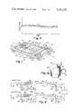
- FIG. 1is a perspective view of a mass flow meter according to the present invention
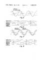
- FIG. 2is a graphical representation of the movement of a typical oscillating conduit
- FIG. 3ais a detailed view of the preferred magnet-coil sensor structure of the flow meter of FIG. 1 which depicts an arrangement with respect to the oscillating conduit which will be understood by those skilled in the art as only one of many acceptable arrangements;
- FIG. 3bis a detailed view of the same preferred magnet-coil velocity sensor arrangement of FIG. 3a, showing the preferred physical size relationship between the coil and the pole faces of the magnet which those skilled in the art will readily understand, insures coil envelopment in a uniform magnetic flux field independent of both conduit oscillatory motion and long term conduit distortion due to ambient fluctuations;
- FIG. 4is an electronic circuit diagram of the circuit employed with the sensor as illustrated in FIGS. 3a and 3b;
- FIG. 5is a graphical representation of the substantially identical signals illustrated in FIG. 2, after compensation for external error signals, ideally generated by the two sensors of the flow meter under no flow conditions;
- FIG. 6is a timing diagram of the readout signals of the flow meter corresponding to the sensor output of FIG. 5;
- FIG. 7is a view similar to that of FIG. 5 illustrating the sensor signals under a flow condition.
- FIG. 8is a timing diagram of the readout signals of the flow meter corresponding to the sensor output of FIG. 7.
- FIG. 1a flow meter device according to a preferred embodiment of the present invention is illustrated in FIG. 1 and generally designated by reference numeral 10.
- flow meter 10is similar to that described in U.S. Pat. No. 4,187,721, the teachings of which are hereby incorporated by reference. Of those teachings the following features of flow meter 10 shown in FIG. 1 are of particular relevance.
- Flow meter 10includes mounting platform 12 to which a U-shaped conduit 14, free of pressure sensitive joints, is mounted by means of conduit support structure 26 adjacent the inlet 15 and the outlet 16 ports in a cantilevered fashion for rotational oscillation.
- drive mechanism 25conventionally in the form of a magnet and coil is carried on U-shaped conduit 14 and oscillating member 30, and activated by conventional drive circuit 27, to rotationally oscillate U-shaped conduit 14 about axis W-W, with resulting Coriolis force deflection of U-shaped conduit 14 being about axis O-O.
- Oscillating member 30may take several forms, i.e., a single leaf spring, a "V" member mounted at the wide end, or a rectangular structure as illustrated.
- the oscillating member 30have substantially the same resonant frequency as the U-shaped conduit 14 has when filled with fluid in the same density range as that of the fluid whose mass flow rate is to be determined, and that the two be mounted so as to be configured as a tuning fork. Accordingly, the U-shaped conduit 14 and the oscillating member 30 are driven by the drive mechanism 25 at their common resonant frequency. Also taught by U.S. Pat. No. 4,187,721 is that the resonant frequency of oscillation for U-shaped conduit 14 about axis W-W should be lower than the resonant frequency of oscillation about axis O-O.
- signals from sensors 33 and 33', or 34 and 34'provide a linear analog signal accurately describing the oscillatory motion of the U-shaped conduit 14. This is unlike previous embodiments, as shown in U.S. Pat. No. 4,187,721, in which deflection of U-shaped conduit 14 was measured by digitally sensing the passage of a fixed mechanical structure relative to the oscillating conduit at predetermined points located near the mid-plane of oscillation.
- the timing signals producedcan be used to determine the time delay between passage of the legs 18 and 20 through the mid-plane of oscillation.
- this time delaywhen multiplied by constants dependent on the geometry of U-shaped conduit 14, equals the fluid mass flow rate through the conduit. It is the purpose of the present invention to utilize this same teaching but to determine the time delay of passage of the legs 18 and 20 by a unique method which increases accuracy.
- flow meter 10 as illustrated in FIG. 1utilizes sensors which generate an analog signal that is substantially a linear function of the actual oscillation of U-shaped conduit 14 as opposed to a digital signal referenced to a structure affixed to the meter's mounting platform.
- sensors 33 and 33'acceleration or velocity sensors are operable, though velocity sensors are preferred.
- sensors 34 and 34'analog position sensors--not to be confused with the digital nominal midpoint position sensors of U.S. Pat. No. 4,187,721--such as strain guages are provided.
- Acceleration and velocity sensorsare preferably spaced from axis W-W at connecting portion 22 since these parameters are greatest at such location.
- Sensors 33 and 33'may also be, and preferably are, located on the outside edges of side legs 18 and 20 rather than on connecting portion 22 as shown in FIG. 1.
- strain of U-shaped conduit 14, as a function of the position of connecting portion 22,is greatest adjacent the mounting of U-shaped conduit 14, and accordingly sensors 34 and 34' are mounted adjacent to, but preferably spaced somewhat from, the solid mounting of U-shaped conduit 14.
- the analog signals generated by a position sensor and an acceleration sensorwill be 180° out of phase and similar in wave form.
- the analog signal generated by a velocity sensorwill be similar in wave form to that of the acceleration signals, but 90° displaced from such signals.
- velocity sensor 40is illustrated and includes a magnet, preferably a permanent magnet, 42 mounted in a fixed manner to mounting platform 12 and a bobbin 44 mounted to U-shaped conduit 14 which carries a coil 45.
- the windings of the coilare adjacent each pole at faces 47 and 48 of magnet 42 such that the coil, except for those straight sections of the coil windings interconnecting the ends at the pole faces, is always in a uniform magnetic flux field.
- Bobbin 44is substantially rectangular in shape.
- magnet 42reciprocates in a vertical direction. Accordingly, the horizontal windings at the upper and lower portions of coil 45 move orthogonally through a substantially uniform magnetic flux field of magnet 42 thus inducing a potential in coil 45 which is a linear function of the velocity of coil 45 relative to adjacent magnet 42.
- the pole faces 47 and 48 of magnet 42are preferably spaced a sufficient distance from each other such that the magnetic flux at each of the faces 47 and 48 is normal to the surface thereof.
- Magnet 42is configured such that faces 47 and 48 are of a dimension greater than the greatest oscillation of U-shaped conduit 14 thereby insuring that the upper and lower portions of coil 45 will be maintained in a uniform magnetic flux field.
- faces 47 and 48are positioned so as to stabilize the gaps relative to coil 45 during oscillation and deflection of U-shaped conduit 14.
- magnet 42may alternatively be mounted on U-shaped conduit 14 and bobbin 44 may be fixedly mounted relative to the coil if desired.
- FIG. 4wherein parallel sensor circuits--one labeled with a prime--are shown, a pair of coils 45 and 45', already described with regard to velocity sensors 40 are illustrated.
- the output signals from such coils 45 and 45'are substantially in the form of waves incorporating frequency components made up of those resulting from conduit oscillation driven by mechanism 25, mass flow rate induced Coriolis forces, and those which result from frequency variations in the oscillation caused by ambient sources such as shock, temperature fluctuations, fluid pressure variations, etc.
- the output from velocity sensor coils 45 and 45'are provided to summing junctions 48 and 48', and from there to integrators 49 and 49', it being understood that several stages of integration may be provided to reduce sensitivity to external vibrations.
- the outputs from integrators 49 and 49'in turn are connected to low pass filters 50 and 50' which pass the low frequency components of the signals from velocity sensor coils 45 and 45', and in turn provide feedback in negative quantities to summing junctions 48 and 48'.
- Filters 50 and 50'include resistors 51 and 51', capacitors 52 and 52' and amplifiers 53 and 53' configured in a conventional arrangement as shown.
- the outputs from integrators 49 and 49'are provided through resistors 54 and 54' to amplifiers 55 and 55' which are operated at saturation levels.
- Comparators 60 and 60'are each connected at one input thereto to the outputs from amplifiers 55 and 55' through resistors 57 and 57', respectively.
- the reference input to comparators 60 and 60'are connected to a reference voltage through resistors 63 and 63' and to, for instance, ground through resistors 65 and 66 which are of differing values. Accordingly, reference voltage Va is provided to comparator 60 while reference Vb is provided to comparator 60'.
- the output from comparator 60is biased on the "ON" position as a function of voltage Va, i.e., switching to the "OFF” position at the bias line a as illustrated with regard to the output from amplifier 55.
- the output signal from comparator 60'is biased to the "OFF" position, i.e., switching at bias line b again as a function of reference voltage Vb.
- the biasingis adjusted such that, throughout the dynamic range of flow meter 10, sensor 45 provides a rising waveform from comparator 60 prior to the rising waveform from comparator 60' despite full deflection, i.e., full range flow, through U-shaped conduit 14.
- the square wave outputs from comparators 60 and 60'are provided to readout circuit 70, which is either the same as that described in U.S. Pat. No. 4,187,721, or that described in published Instruction Manual Model B Mass Flow Meter, available from Micro Motion, Inc., 7070 Winchester Circle, Boulder, Colo. 80301.
- the readout circuit 70fundamentally constitutes either an up-down counter as described in detail in U.S. Pat. No. 4,187,721 or an analog integrator as described in Instruction Manual Model B Mass Flow Meter. Both of these circuit approaches are intended to measure the time delays of the rising and falling portions of the square wave signals from comparators 60 and 60' that are inputted to readout circuit 70.
- sensors 33 and 33', or 34 and 34'provide signals which are linear functions of the actual oscillatory motion of U-shaped conduit 14.
- Position sensorssuch as would be employed as sensors 34 and 34', are preferably strain gauges which vary in electrical characterisitics, typically resistance, as a function of the strains induced in U-shaped conduit 14.
- Such sensorsare preferably mounted adjacent inlet 15 and outlet 16, positions at which the strains are greatest, but spaced somewhat therefrom to avoid influencing the strain as a result of the solid mounting of U-shaped conduit 14 to supports 26.
- Sensors 33 and 33', mounted at the intersection of legs 18 and 20, and connecting portion 22,are preferably acceleration or velocity sensors. Acceleration sensors are more sensitive to outside vibrations, but this drawback may be avoided by providing several stages of integration before processing the signals for time delay measurements. Such integration is provided through circuits 49 and 49'.
- the second integral of an acceleration sensor's outputis equivalent to the primary output of position sensors 34 and 34', while the first integral of the output of an acceleration sensor is equivalent to the signal from velocity sensor 40.
- Velocity sensor 40illustrated in FIGS. 3a and 3b, appears to provide an economical and most effective device to serve as sensors 33 and 33'. This is more a result of ease of construction, availability and stability of appropriate circuitry components as opposed to theoretical advantage. With one or more stages of integration, at the sensor output, velocity sensor 40 employed in flow meter 10 provides long-term stability over the heretofore most troublesome operating condition, i.e., substantial temperature changes of 200° C. or more of the fluid flowing through the U-shaped conduit 14. Even a direct blast with refrigerants upon U-shaped conduit 14 fails to disrupt the sensitivity and accuracy of flow meter 10 other than for a few cycles thereof. The same conditions seriously disrupt the operation of prior oscillating conduit type Coriolis flow meters.
- circuit 70fundamentally consists of either an up-down counter as described in U.S. Pat. No. 4,187,721, or an analog integrator as described in Instruction Manual Model B Mass Flow Meter. Since either the up-down counter or the analog integrator circuit essentially achieve the same purpose, the following discussion of how circuit 70 functions for convenience will not be repeated for the two approaches. Instead the discussion refers to the composite term "counter/integrator", indicating that the functioning as described applies to either.
- the outputs of integrators 49 and 49' of FIG. 4, as shown in FIG. 5, after the extraneous frequency components have been cancelledcomprise substantially in phase, identical oscillating waves, under no flow conditions.
- the square wave signals from comparators 60 and 60' to readout circuit 70are, as illustrated in FIG. 6, at an "ON" level for a longer period with regard to the output from comparator 60 than with regard to the output from comparator 60'.
- the down count/integration which is initiated by the rising edge of the signal from comparator 60, and terminated by the rising edge of the signal from comparator 60'is always a positive quantity with the count/integration signal level indicating the time delay between such events.
- the up-count/integration portion of readout circuit 70which is initiated by the falling edge of the signal from comparator 60', and terminated upon the falling edge of the output of comparator 60, is also always a positive quantity representative of time delay. As discussed above, this relationship is maintained by adjusting the relative magnitude of reference voltages Va and Vb. Under no flow conditions, the counts/integrations, up and down, are identical.
- the instant inventionaddresses the problem of frequency variations in the oscillatory travel of a U-shaped conduit as a result of ambient changes in the physical factors affecting such oscillation.
- sensorswhich generate analog signals as a linear function of the oscillatory movement of the U-shaped conduit, and preferably with circuitry which integrates, filters and cancels the frequency components from the sensor outputs of such oscillation which correspond to physical variations over periods other than that caused by drive mechanism 25, it is possible to provide a stable and accurate mass flow rate meter.
- the output of the sensorsbe integrated at least once, whether the signals are from acceleration, velocity or position sensors and particularly in the case of an acceleration sensor through several stages of integration.
Landscapes
- Physics & Mathematics (AREA)
- Fluid Mechanics (AREA)
- General Physics & Mathematics (AREA)
- Measuring Volume Flow (AREA)
Abstract
Description
COMPONENT TABLE ______________________________________49, 49', 53, Motorola type 155 Amplifiers FET 53', 55 and 55' Operational Amplifiers Resistors 51 and 51' 500K ohm, .25 watt CC*Resistors 54 and 54' 10K ohm, .25watt CC Resistors 57 and 57' 1.0Kohm CC Resistors 63 and 63' 5.6Kohm CC Resistor 65 100K ohmCC Resistor 66 150K ohmCC Capacitors 52 and 52' 1 microfaradlow leakage Comparators 60 and 60' National Semiconductor No. LM111 ______________________________________ *Carbon composition
Claims (27)
Priority Applications (2)
| Application Number | Priority Date | Filing Date | Title |
|---|---|---|---|
| US06/280,297US4422338A (en) | 1981-02-17 | 1981-07-06 | Method and apparatus for mass flow measurement |
| CA000396361ACA1176754A (en) | 1981-02-17 | 1982-02-16 | Method and apparatus for mass flow measurement |
Applications Claiming Priority (2)
| Application Number | Priority Date | Filing Date | Title |
|---|---|---|---|
| US23526881A | 1981-02-17 | 1981-02-17 | |
| US06/280,297US4422338A (en) | 1981-02-17 | 1981-07-06 | Method and apparatus for mass flow measurement |
Related Parent Applications (1)
| Application Number | Title | Priority Date | Filing Date |
|---|---|---|---|
| US23526881AContinuation-In-Part | 1981-02-17 | 1981-02-17 |
Publications (2)
| Publication Number | Publication Date |
|---|---|
| US4422338Atrue US4422338A (en) | 1983-12-27 |
| US4422338B1 US4422338B1 (en) | 1987-07-14 |
Family
ID=26928749
Family Applications (1)
| Application Number | Title | Priority Date | Filing Date |
|---|---|---|---|
| US06/280,297Expired - LifetimeUS4422338A (en) | 1981-02-17 | 1981-07-06 | Method and apparatus for mass flow measurement |
Country Status (2)
| Country | Link |
|---|---|
| US (1) | US4422338A (en) |
| CA (1) | CA1176754A (en) |
Cited By (89)
| Publication number | Priority date | Publication date | Assignee | Title |
|---|---|---|---|---|
| WO1985005677A1 (en)* | 1984-06-04 | 1985-12-19 | Exac Corporation | Apparatus for mass flow rate and density measurement |
| US4559833A (en)* | 1982-09-30 | 1985-12-24 | Smith Meter Inc. | Meter for measuring mass flow rate |
| US4655089A (en)* | 1985-06-07 | 1987-04-07 | Smith Meter Inc. | Mass flow meter and signal processing system |
| US4655075A (en)* | 1984-09-26 | 1987-04-07 | University Of Delaware | Vibrating tube densimeter |
| US4689989A (en)* | 1985-06-24 | 1987-09-01 | Chevron Research Company | Method and apparatus for testing the outflow from hydrocarbon wells on site |
| EP0188572A4 (en)* | 1984-07-11 | 1987-10-26 | Exac Corp | Improved apparatus for mass flow rate and density measurement. |
| EP0244692A1 (en)* | 1986-05-06 | 1987-11-11 | BELLCO S.p.A. | Differential mass flowmeter |
| US4711132A (en)* | 1984-06-04 | 1987-12-08 | Exac Corporation | Apparatus for mass flow rate and density measurement |
| US4716771A (en)* | 1986-02-11 | 1988-01-05 | K-Flow Division Of Kane Steel Co., Inc. | Symmetrical mass flow meter |
| US4733569A (en)* | 1985-12-16 | 1988-03-29 | K-Flow Division Of Kane Steel Co., Inc. | Mass flow meter |
| US4738144A (en)* | 1986-10-03 | 1988-04-19 | Micro Motion, Inc. | Drive means for oscillating flow tubes of parallel path coriolis mass flow rate meter |
| US4738143A (en)* | 1985-08-29 | 1988-04-19 | Micro Motion, Incorporated | High temperature Coriolis mass flow rate meter |
| US4756198A (en)* | 1986-01-24 | 1988-07-12 | Exac Corporation | Sensor apparatus for mass flow rate measurement system |
| US4777833A (en)* | 1986-11-12 | 1988-10-18 | Micro Motion, Inc. | Ferromagnetic drive and velocity sensors for a coriolis mass flow rate meter |
| EP0300301A1 (en) | 1987-07-22 | 1989-01-25 | Exac Corporation | Apparatus and method for measuring the mass flow rate of material flowing through at least one vibrating conduit |
| US4823614A (en)* | 1986-04-28 | 1989-04-25 | Dahlin Erik B | Coriolis-type mass flowmeter |
| US4823592A (en)* | 1988-02-05 | 1989-04-25 | Micro Motion, Inc. | Test apparatus for proving the performance of mass flow meters |
| US4860594A (en)* | 1988-03-01 | 1989-08-29 | Gmi Engineering & Management Institute | Apparatus and method for measuring mass flow and density |
| US4876898A (en)* | 1988-10-13 | 1989-10-31 | Micro Motion, Inc. | High temperature coriolis mass flow rate meter |
| US4891991A (en)* | 1986-10-28 | 1990-01-09 | The Foxboro Company | Coriolis-type mass flowmeter |
| US4911020A (en)* | 1986-10-28 | 1990-03-27 | The Foxboro Company | Coriolis-type mass flowmeter circuitry |
| US4934196A (en)* | 1989-06-02 | 1990-06-19 | Micro Motion, Inc. | Coriolis mass flow rate meter having a substantially increased noise immunity |
| US4955239A (en)* | 1986-05-22 | 1990-09-11 | Micro Motion, Inc. | Apparatus for electrically interconnecting vibrating structures |
| WO1990015310A1 (en)* | 1989-06-09 | 1990-12-13 | Micro Motion, Inc. | Improved stability coriolis mass flow meter |
| DE3923409A1 (en)* | 1989-07-14 | 1991-01-24 | Danfoss As | MASS FLOW MEASURING DEVICE WORKING ACCORDING TO THE CORIOLIS PRINCIPLE |
| US4996871A (en)* | 1989-06-02 | 1991-03-05 | Micro Motion, Inc. | Coriolis densimeter having substantially increased noise immunity |
| US5027662A (en)* | 1987-07-15 | 1991-07-02 | Micro Motion, Inc. | Accuracy mass flow meter with asymmetry and viscous damping compensation |
| US5050439A (en)* | 1986-10-28 | 1991-09-24 | The Foxboro Company | Coriolis-type mass flowmeter circuitry |
| US5228327A (en)* | 1991-07-11 | 1993-07-20 | Micro Motion, Inc. | Technique for determining a mechanical zero value for a coriolis meter |
| US5231884A (en)* | 1991-07-11 | 1993-08-03 | Micro Motion, Inc. | Technique for substantially eliminating temperature induced measurement errors from a coriolis meter |
| US5271281A (en)* | 1986-10-28 | 1993-12-21 | The Foxboro Company | Coriolis-type mass flowmeter |
| US5275061A (en)* | 1991-05-13 | 1994-01-04 | Exac Corporation | Coriolis mass flowmeter |
| US5304001A (en)* | 1989-09-27 | 1994-04-19 | Union Carbide Chemicals And Plastics Technology Corporation | Method and apparatus for metering and mixing non-compressible and compressible fluids |
| US5343764A (en)* | 1986-10-28 | 1994-09-06 | The Foxboro Company | Coriolis-type mass flowmeter |
| US5351561A (en)* | 1992-11-06 | 1994-10-04 | Endress+Hauser Flowtec Ag | Coriolis-type flow meter having an improved temperature range of operation |
| US5373745A (en)* | 1991-02-05 | 1994-12-20 | Direct Measurement Corporation | Single path radial mode Coriolis mass flow rate meter |
| US5423225A (en)* | 1991-02-05 | 1995-06-13 | Direct Measurement Corp. | Single path radial mode coriolis mass flow rate meter |
| US5429002A (en)* | 1994-05-11 | 1995-07-04 | Schlumberger Industries, Inc. | Coriolis-type fluid mass flow rate measurement device and method employing a least-squares algorithm |
| US5448921A (en)* | 1991-02-05 | 1995-09-12 | Direct Measurement Corporation | Coriolis mass flow rate meter |
| US5473949A (en)* | 1991-02-05 | 1995-12-12 | Direct Measurement Corporation | Coriolis mass flow rate meter having adjustable pressure and density sensitivity |
| US5531126A (en)* | 1993-07-21 | 1996-07-02 | Endress + Hauser Flowtec Ag | Coriolis-type mass flow sensor with flow condition compensating |
| US5546814A (en)* | 1994-10-26 | 1996-08-20 | The Foxboro Company | Parallel-flow coriolis-type mass flowmeter with flow-dividing manifold |
| US5549009A (en)* | 1990-09-04 | 1996-08-27 | Joerg Zaschel | Apparatus for determining and dosing mass flows |
| US5602346A (en)* | 1994-06-06 | 1997-02-11 | Oval Corporation | Mass flowmeter converter |
| US5627326A (en)* | 1992-04-24 | 1997-05-06 | Mmg Automatika Muvek Reszvenytarsasag | Coriolis type apparatus for measuring mass flow of a fluid stream |
| US5753827A (en)* | 1995-10-17 | 1998-05-19 | Direct Measurement Corporation | Coriolis meteR having a geometry insensitive to changes in fluid pressure and density and method of operation thereof |
| RU2113693C1 (en)* | 1997-07-10 | 1998-06-20 | Александр Львович Дондошанский | Mass flowmeter |
| US5804741A (en)* | 1996-11-08 | 1998-09-08 | Schlumberger Industries, Inc. | Digital phase locked loop signal processing for coriolis mass flow meter |
| US5827979A (en)* | 1996-04-22 | 1998-10-27 | Direct Measurement Corporation | Signal processing apparati and methods for attenuating shifts in zero intercept attributable to a changing boundary condition in a Coriolis mass flow meter |
| RU2122182C1 (en)* | 1989-06-09 | 1998-11-20 | Микро Моушн, Инк. | Device for measuring of mass flow rate of fluid materials |
| US5907104A (en)* | 1995-12-08 | 1999-05-25 | Direct Measurement Corporation | Signal processing and field proving methods and circuits for a coriolis mass flow meter |
| USRE36376E (en)* | 1989-06-09 | 1999-11-09 | Micro Motion, Inc. | Stability coriolis mass flow meter |
| US6092429A (en)* | 1997-12-04 | 2000-07-25 | Micro Motion, Inc. | Driver for oscillating a vibrating conduit |
| US6227059B1 (en) | 1999-01-12 | 2001-05-08 | Direct Measurement Corporation | System and method for employing an imaginary difference signal component to compensate for boundary condition effects on a Coriolis mass flow meter |
| US6272438B1 (en)* | 1998-08-05 | 2001-08-07 | Micro Motion, Inc. | Vibrating conduit parameter sensors, methods and computer program products for generating residual-flexibility-compensated mass flow estimates |
| US6311136B1 (en) | 1997-11-26 | 2001-10-30 | Invensys Systems, Inc. | Digital flowmeter |
| US6513392B1 (en) | 1998-12-08 | 2003-02-04 | Emerson Electric Co. | Coriolis mass flow controller |
| US20030212509A1 (en)* | 2002-03-29 | 2003-11-13 | Henry Manus P. | Startup and operational techniques for a digital flowmeter |
| US6748813B1 (en) | 1998-12-08 | 2004-06-15 | Emerson Electric Company | Coriolis mass flow controller |
| US6763730B1 (en) | 1999-05-25 | 2004-07-20 | Abb Limited | Vibrating tube meter |
| US20040206189A1 (en)* | 2000-03-23 | 2004-10-21 | Invensys Systems, Inc. | Correcting for two-phase flow in a digital flowmeter |
| US20040221660A1 (en)* | 2003-05-05 | 2004-11-11 | Dutton Robert E. | Two-phase steam measurement system |
| US20040258541A1 (en)* | 2002-01-03 | 2004-12-23 | Greg Glatzmaier | Orbital fluid pump |
| US20050021259A1 (en)* | 2003-05-30 | 2005-01-27 | Troy Wray | Phase measurement in measuring device |
| US20050022611A1 (en)* | 2003-06-26 | 2005-02-03 | John Hemp | Viscosity-corrected flowmeter |
| US20050034537A1 (en)* | 2003-08-13 | 2005-02-17 | Henry Manus P. | Correcting frequency in flowtube measurements |
| US20050081643A1 (en)* | 2003-02-10 | 2005-04-21 | Mattar Wade M. | Multiphase coriolis flowmeter |
| US20050110547A1 (en)* | 2003-11-21 | 2005-05-26 | Glatzmaier Greg C. | Phase angle control method |
| US20050150311A1 (en)* | 2004-01-02 | 2005-07-14 | Emerson Electric Co. | Coriolis mass flow sensor |
| US20050193832A1 (en)* | 2003-02-10 | 2005-09-08 | Tombs Michael S. | Multi-phase Coriolis flowmeter |
| US20050284237A1 (en)* | 1997-11-26 | 2005-12-29 | Invensys Systems, Inc., A Massachusetts Corporation | Correcting for two-phase flow in a digital flowmeter |
| US20070157739A1 (en)* | 2006-01-06 | 2007-07-12 | Integrated Sensing Systems, Inc. | Microfluidic device and method of operation |
| US20070186684A1 (en)* | 2003-07-24 | 2007-08-16 | Pham Nghieu Q | Vibrating tube mass flow meter |
| US7404336B2 (en) | 2000-03-23 | 2008-07-29 | Invensys Systems, Inc. | Correcting for two-phase flow in a digital flowmeter |
| US20090019947A1 (en)* | 1999-11-22 | 2009-01-22 | Invensys Systems, Inc. | Correcting for Two-Phase Flow in a Digital Flowmeter |
| US20090173167A1 (en)* | 2008-01-07 | 2009-07-09 | Susumu Takayanagi | Flowmeter |
| US20110000315A1 (en)* | 2009-07-03 | 2011-01-06 | Keyence Corporation | Coriolis Mass Flow Meter |
| US20110035166A1 (en)* | 1997-11-26 | 2011-02-10 | Invensys Systems, Inc. | Drive techniques for a digital flowmeter |
| US20110271755A1 (en)* | 2008-08-15 | 2011-11-10 | Waters Technologies Corporation | Apparatus And Methods For The Measurement Of Mass Related Parameters |
| WO2011159355A2 (en) | 2010-06-15 | 2011-12-22 | Biofilm Ip, Llc | Methods, devices systems for extraction of thermal energy from a heat conducting metal conduit |
| US8126661B2 (en) | 2006-08-28 | 2012-02-28 | Henry Manus P | Wet gas measurement |
| WO2013090828A2 (en) | 2011-12-16 | 2013-06-20 | Biofilm Ip, Llc | Cryogenic injection compositions, systems and methods for cryogenically modulating flow in a conduit |
| WO2015038961A1 (en) | 2013-09-13 | 2015-03-19 | Biofilm Ip, Llc | Magneto-cryogenic valves, systems and methods for modulating flow in a conduit |
| US9046400B2 (en) | 1997-11-26 | 2015-06-02 | Invensys Systems, Inc. | Digital flowmeter |
| US9080908B2 (en) | 2013-07-24 | 2015-07-14 | Jesse Yoder | Flowmeter design for large diameter pipes |
| WO2019002563A2 (en) | 2017-06-30 | 2019-01-03 | Norsk Titanium As | Solidification refinement and general phase transformation control through application of in situ gas jet impingement in metal additive manufacturing |
| EP3129755B1 (en)* | 2014-04-07 | 2022-07-20 | Micro Motion, Inc. | Improved vibrating flowmeter and related methods |
| CN116338526A (en)* | 2023-05-08 | 2023-06-27 | 安徽大学 | A Simulator and Diagnosis Method of Traction Transformer Winding Local Cumulative Warpage |
| US12009143B2 (en)* | 2018-08-08 | 2024-06-11 | Endress+Hauser Flowtec Ag | Method of producing a coil device, coil device, measuring transducer with coil device, instrument having a measuring transducer |
Citations (11)
| Publication number | Priority date | Publication date | Assignee | Title |
|---|---|---|---|---|
| US2865201A (en)* | 1954-08-26 | 1958-12-23 | Roth Wilfred | Gyroscopic mass flowmeter |
| US3087325A (en)* | 1961-08-07 | 1963-04-30 | Roth Wilfred | Gyroscopic mass flowmeters |
| US3108475A (en)* | 1961-02-13 | 1963-10-29 | Wilfred Roth | Gyroscopic mass flowmeter |
| US3132512A (en)* | 1961-02-13 | 1964-05-12 | Roth Wilfred | Gyroscopic mass flowmeter |
| US3276257A (en)* | 1960-02-02 | 1966-10-04 | Roth Wilfred | Gyroscopic mass flowmeters |
| US3329019A (en)* | 1964-10-26 | 1967-07-04 | Anatole J Sipin | Mass flow metering means |
| US3355944A (en)* | 1964-09-03 | 1967-12-05 | Anatole J Sipin | Mass flow metering means |
| US3485098A (en)* | 1964-09-03 | 1969-12-23 | Anatole J Sipin | Mass flow metering means |
| US4187721A (en)* | 1977-07-25 | 1980-02-12 | S & F Associates | Method and structure for flow measurement |
| US4192184A (en)* | 1978-11-13 | 1980-03-11 | Halliburton Company | Mass flowmeter |
| US4311054A (en)* | 1978-11-13 | 1982-01-19 | Halliburton Company | Mass flowmeter with sensor gain control |
- 1981
- 1981-07-06USUS06/280,297patent/US4422338A/ennot_activeExpired - Lifetime
- 1982
- 1982-02-16CACA000396361Apatent/CA1176754A/ennot_activeExpired
Patent Citations (11)
| Publication number | Priority date | Publication date | Assignee | Title |
|---|---|---|---|---|
| US2865201A (en)* | 1954-08-26 | 1958-12-23 | Roth Wilfred | Gyroscopic mass flowmeter |
| US3276257A (en)* | 1960-02-02 | 1966-10-04 | Roth Wilfred | Gyroscopic mass flowmeters |
| US3108475A (en)* | 1961-02-13 | 1963-10-29 | Wilfred Roth | Gyroscopic mass flowmeter |
| US3132512A (en)* | 1961-02-13 | 1964-05-12 | Roth Wilfred | Gyroscopic mass flowmeter |
| US3087325A (en)* | 1961-08-07 | 1963-04-30 | Roth Wilfred | Gyroscopic mass flowmeters |
| US3355944A (en)* | 1964-09-03 | 1967-12-05 | Anatole J Sipin | Mass flow metering means |
| US3485098A (en)* | 1964-09-03 | 1969-12-23 | Anatole J Sipin | Mass flow metering means |
| US3329019A (en)* | 1964-10-26 | 1967-07-04 | Anatole J Sipin | Mass flow metering means |
| US4187721A (en)* | 1977-07-25 | 1980-02-12 | S & F Associates | Method and structure for flow measurement |
| US4192184A (en)* | 1978-11-13 | 1980-03-11 | Halliburton Company | Mass flowmeter |
| US4311054A (en)* | 1978-11-13 | 1982-01-19 | Halliburton Company | Mass flowmeter with sensor gain control |
Non-Patent Citations (2)
| Title |
|---|
| Halliday et al., "Physics for Student of Science and Education", Published by Wiley and Sons Inc., 1962.* |
| Micro Motion Inc., Instruction Manual-Model B Mass Flow Meter.* |
Cited By (160)
| Publication number | Priority date | Publication date | Assignee | Title |
|---|---|---|---|---|
| US4559833A (en)* | 1982-09-30 | 1985-12-24 | Smith Meter Inc. | Meter for measuring mass flow rate |
| US4711132A (en)* | 1984-06-04 | 1987-12-08 | Exac Corporation | Apparatus for mass flow rate and density measurement |
| WO1985005677A1 (en)* | 1984-06-04 | 1985-12-19 | Exac Corporation | Apparatus for mass flow rate and density measurement |
| EP0188572A4 (en)* | 1984-07-11 | 1987-10-26 | Exac Corp | Improved apparatus for mass flow rate and density measurement. |
| US4655075A (en)* | 1984-09-26 | 1987-04-07 | University Of Delaware | Vibrating tube densimeter |
| US4655089A (en)* | 1985-06-07 | 1987-04-07 | Smith Meter Inc. | Mass flow meter and signal processing system |
| US4689989A (en)* | 1985-06-24 | 1987-09-01 | Chevron Research Company | Method and apparatus for testing the outflow from hydrocarbon wells on site |
| US4738143A (en)* | 1985-08-29 | 1988-04-19 | Micro Motion, Incorporated | High temperature Coriolis mass flow rate meter |
| US4733569A (en)* | 1985-12-16 | 1988-03-29 | K-Flow Division Of Kane Steel Co., Inc. | Mass flow meter |
| US4756198A (en)* | 1986-01-24 | 1988-07-12 | Exac Corporation | Sensor apparatus for mass flow rate measurement system |
| US4716771A (en)* | 1986-02-11 | 1988-01-05 | K-Flow Division Of Kane Steel Co., Inc. | Symmetrical mass flow meter |
| US4823614A (en)* | 1986-04-28 | 1989-04-25 | Dahlin Erik B | Coriolis-type mass flowmeter |
| EP0244692A1 (en)* | 1986-05-06 | 1987-11-11 | BELLCO S.p.A. | Differential mass flowmeter |
| US4781068A (en)* | 1986-05-06 | 1988-11-01 | Bellco Spa | Differential mass flowmeter |
| US4955239A (en)* | 1986-05-22 | 1990-09-11 | Micro Motion, Inc. | Apparatus for electrically interconnecting vibrating structures |
| US4738144A (en)* | 1986-10-03 | 1988-04-19 | Micro Motion, Inc. | Drive means for oscillating flow tubes of parallel path coriolis mass flow rate meter |
| US5343764A (en)* | 1986-10-28 | 1994-09-06 | The Foxboro Company | Coriolis-type mass flowmeter |
| US5271281A (en)* | 1986-10-28 | 1993-12-21 | The Foxboro Company | Coriolis-type mass flowmeter |
| US5050439A (en)* | 1986-10-28 | 1991-09-24 | The Foxboro Company | Coriolis-type mass flowmeter circuitry |
| US4891991A (en)* | 1986-10-28 | 1990-01-09 | The Foxboro Company | Coriolis-type mass flowmeter |
| US4911020A (en)* | 1986-10-28 | 1990-03-27 | The Foxboro Company | Coriolis-type mass flowmeter circuitry |
| US4777833A (en)* | 1986-11-12 | 1988-10-18 | Micro Motion, Inc. | Ferromagnetic drive and velocity sensors for a coriolis mass flow rate meter |
| US5027662A (en)* | 1987-07-15 | 1991-07-02 | Micro Motion, Inc. | Accuracy mass flow meter with asymmetry and viscous damping compensation |
| EP0300301A1 (en) | 1987-07-22 | 1989-01-25 | Exac Corporation | Apparatus and method for measuring the mass flow rate of material flowing through at least one vibrating conduit |
| US4823592A (en)* | 1988-02-05 | 1989-04-25 | Micro Motion, Inc. | Test apparatus for proving the performance of mass flow meters |
| US4860594A (en)* | 1988-03-01 | 1989-08-29 | Gmi Engineering & Management Institute | Apparatus and method for measuring mass flow and density |
| AU609335B2 (en)* | 1988-10-13 | 1991-04-26 | Micro Motion, Inc. | High temperature coriolis mass flow rater meter |
| US4876898A (en)* | 1988-10-13 | 1989-10-31 | Micro Motion, Inc. | High temperature coriolis mass flow rate meter |
| US4934196A (en)* | 1989-06-02 | 1990-06-19 | Micro Motion, Inc. | Coriolis mass flow rate meter having a substantially increased noise immunity |
| US4996871A (en)* | 1989-06-02 | 1991-03-05 | Micro Motion, Inc. | Coriolis densimeter having substantially increased noise immunity |
| EP0848234A3 (en)* | 1989-06-09 | 1998-10-14 | Micro Motion Inc. | Improved stability Coriolis mass flow meter |
| EP0848235A3 (en)* | 1989-06-09 | 1998-10-14 | Micro Motion Inc. | Improved stability Coriolis mass flow meter |
| WO1990015310A1 (en)* | 1989-06-09 | 1990-12-13 | Micro Motion, Inc. | Improved stability coriolis mass flow meter |
| AU625788B2 (en)* | 1989-06-09 | 1992-07-16 | Micro Motion, Inc. | Improved stability coriolis mass flow meter |
| USRE36376E (en)* | 1989-06-09 | 1999-11-09 | Micro Motion, Inc. | Stability coriolis mass flow meter |
| RU2122182C1 (en)* | 1989-06-09 | 1998-11-20 | Микро Моушн, Инк. | Device for measuring of mass flow rate of fluid materials |
| DE3923409A1 (en)* | 1989-07-14 | 1991-01-24 | Danfoss As | MASS FLOW MEASURING DEVICE WORKING ACCORDING TO THE CORIOLIS PRINCIPLE |
| US5403089A (en)* | 1989-09-27 | 1995-04-04 | Union Carbide Chemicals & Plastics Technology Corporation | Method and apparatus for metering and mixing non-compressible and compressible fluids |
| US5304001A (en)* | 1989-09-27 | 1994-04-19 | Union Carbide Chemicals And Plastics Technology Corporation | Method and apparatus for metering and mixing non-compressible and compressible fluids |
| US5549009A (en)* | 1990-09-04 | 1996-08-27 | Joerg Zaschel | Apparatus for determining and dosing mass flows |
| US5373745A (en)* | 1991-02-05 | 1994-12-20 | Direct Measurement Corporation | Single path radial mode Coriolis mass flow rate meter |
| US5423225A (en)* | 1991-02-05 | 1995-06-13 | Direct Measurement Corp. | Single path radial mode coriolis mass flow rate meter |
| US5448921A (en)* | 1991-02-05 | 1995-09-12 | Direct Measurement Corporation | Coriolis mass flow rate meter |
| US5473949A (en)* | 1991-02-05 | 1995-12-12 | Direct Measurement Corporation | Coriolis mass flow rate meter having adjustable pressure and density sensitivity |
| US5497665A (en)* | 1991-02-05 | 1996-03-12 | Direct Measurement Corporation | Coriolis mass flow rate meter having adjustable pressure and density sensitivity |
| US5576500A (en)* | 1991-02-05 | 1996-11-19 | Direct Measurement Corporation | Coriolis mass flow rate meter having means for modifying angular velocity gradient positioned within a conduit |
| US5275061A (en)* | 1991-05-13 | 1994-01-04 | Exac Corporation | Coriolis mass flowmeter |
| US5228327A (en)* | 1991-07-11 | 1993-07-20 | Micro Motion, Inc. | Technique for determining a mechanical zero value for a coriolis meter |
| RU2119149C1 (en)* | 1991-07-11 | 1998-09-20 | Микро Моушн, Инк. | Method for determination of mechanical zero of coriolis meter, coriolis meter for measuring specific flow rate of liquid medium flowing through it |
| US5231884A (en)* | 1991-07-11 | 1993-08-03 | Micro Motion, Inc. | Technique for substantially eliminating temperature induced measurement errors from a coriolis meter |
| US5627326A (en)* | 1992-04-24 | 1997-05-06 | Mmg Automatika Muvek Reszvenytarsasag | Coriolis type apparatus for measuring mass flow of a fluid stream |
| US5351561A (en)* | 1992-11-06 | 1994-10-04 | Endress+Hauser Flowtec Ag | Coriolis-type flow meter having an improved temperature range of operation |
| US5531126A (en)* | 1993-07-21 | 1996-07-02 | Endress + Hauser Flowtec Ag | Coriolis-type mass flow sensor with flow condition compensating |
| US5429002A (en)* | 1994-05-11 | 1995-07-04 | Schlumberger Industries, Inc. | Coriolis-type fluid mass flow rate measurement device and method employing a least-squares algorithm |
| US5602346A (en)* | 1994-06-06 | 1997-02-11 | Oval Corporation | Mass flowmeter converter |
| US5546814A (en)* | 1994-10-26 | 1996-08-20 | The Foxboro Company | Parallel-flow coriolis-type mass flowmeter with flow-dividing manifold |
| US5753827A (en)* | 1995-10-17 | 1998-05-19 | Direct Measurement Corporation | Coriolis meteR having a geometry insensitive to changes in fluid pressure and density and method of operation thereof |
| US5907104A (en)* | 1995-12-08 | 1999-05-25 | Direct Measurement Corporation | Signal processing and field proving methods and circuits for a coriolis mass flow meter |
| US5827979A (en)* | 1996-04-22 | 1998-10-27 | Direct Measurement Corporation | Signal processing apparati and methods for attenuating shifts in zero intercept attributable to a changing boundary condition in a Coriolis mass flow meter |
| US5804741A (en)* | 1996-11-08 | 1998-09-08 | Schlumberger Industries, Inc. | Digital phase locked loop signal processing for coriolis mass flow meter |
| RU2113693C1 (en)* | 1997-07-10 | 1998-06-20 | Александр Львович Дондошанский | Mass flowmeter |
| US9046400B2 (en) | 1997-11-26 | 2015-06-02 | Invensys Systems, Inc. | Digital flowmeter |
| US20050209794A1 (en)* | 1997-11-26 | 2005-09-22 | Henry Manus P | Digital flowmeter |
| US20110035166A1 (en)* | 1997-11-26 | 2011-02-10 | Invensys Systems, Inc. | Drive techniques for a digital flowmeter |
| US6311136B1 (en) | 1997-11-26 | 2001-10-30 | Invensys Systems, Inc. | Digital flowmeter |
| US6507791B2 (en) | 1997-11-26 | 2003-01-14 | Invensys Systems, Inc. | Digital flowmeter |
| US8467986B2 (en) | 1997-11-26 | 2013-06-18 | Invensys Systems, Inc. | Drive techniques for a digital flowmeter |
| US7124646B2 (en) | 1997-11-26 | 2006-10-24 | Invensys Systems, Inc. | Correcting for two-phase flow in a digital flowmeter |
| US9014997B2 (en) | 1997-11-26 | 2015-04-21 | Invensys Systems, Inc. | Drive techniques for a digital flowmeter |
| US20040031328A1 (en)* | 1997-11-26 | 2004-02-19 | The Foxboro Company | Digital flowmeter |
| US20050284237A1 (en)* | 1997-11-26 | 2005-12-29 | Invensys Systems, Inc., A Massachusetts Corporation | Correcting for two-phase flow in a digital flowmeter |
| US6754594B2 (en) | 1997-11-26 | 2004-06-22 | Invensys Systems, Inc. | Digital flowmeter |
| US20100107778A1 (en)* | 1997-11-26 | 2010-05-06 | Invensys Systems, Inc. | Digital flowmeter |
| US7136761B2 (en) | 1997-11-26 | 2006-11-14 | Invensys Systems, Inc. | Digital flowmeter |
| US9279710B2 (en) | 1997-11-26 | 2016-03-08 | Invensys Systems, Inc. | Digital flowmeter |
| US20070124090A1 (en)* | 1997-11-26 | 2007-05-31 | Invensys Systems, Inc. | Digital flowmeter |
| US8000906B2 (en) | 1997-11-26 | 2011-08-16 | Invensys Systems, Inc. | Digital flowmeter |
| US9091580B2 (en) | 1997-11-26 | 2015-07-28 | Invensys Systems, Inc. | Digital flowmeter |
| US9080909B2 (en) | 1997-11-26 | 2015-07-14 | Invensys Systems, Inc. | Digital flowmeter |
| US9200936B2 (en) | 1997-11-26 | 2015-12-01 | Invensys Systems, Inc. | Digital flowmeter |
| US9046401B2 (en) | 1997-11-26 | 2015-06-02 | Invensys Systems, Inc. | Correcting for two-phase flow in a digital flowmeter |
| US6917887B2 (en) | 1997-11-26 | 2005-07-12 | Invensys Systems, Inc. | Digital flowmeter |
| US7571062B2 (en) | 1997-11-26 | 2009-08-04 | Invensys Systems, Inc. | Digital flowmeter |
| US6092429A (en)* | 1997-12-04 | 2000-07-25 | Micro Motion, Inc. | Driver for oscillating a vibrating conduit |
| US6272438B1 (en)* | 1998-08-05 | 2001-08-07 | Micro Motion, Inc. | Vibrating conduit parameter sensors, methods and computer program products for generating residual-flexibility-compensated mass flow estimates |
| US6748813B1 (en) | 1998-12-08 | 2004-06-15 | Emerson Electric Company | Coriolis mass flow controller |
| US20030131668A1 (en)* | 1998-12-08 | 2003-07-17 | Emerson Electric Co. | Coriolis mass flow controller |
| US6513392B1 (en) | 1998-12-08 | 2003-02-04 | Emerson Electric Co. | Coriolis mass flow controller |
| US6227059B1 (en) | 1999-01-12 | 2001-05-08 | Direct Measurement Corporation | System and method for employing an imaginary difference signal component to compensate for boundary condition effects on a Coriolis mass flow meter |
| US6763730B1 (en) | 1999-05-25 | 2004-07-20 | Abb Limited | Vibrating tube meter |
| US9021892B2 (en) | 1999-11-22 | 2015-05-05 | Invensys Systems, Inc. | Correcting for two-phase flow in a digital flowmeter |
| US7784360B2 (en) | 1999-11-22 | 2010-08-31 | Invensys Systems, Inc. | Correcting for two-phase flow in a digital flowmeter |
| US20090019947A1 (en)* | 1999-11-22 | 2009-01-22 | Invensys Systems, Inc. | Correcting for Two-Phase Flow in a Digital Flowmeter |
| US20040206189A1 (en)* | 2000-03-23 | 2004-10-21 | Invensys Systems, Inc. | Correcting for two-phase flow in a digital flowmeter |
| US6981424B2 (en) | 2000-03-23 | 2006-01-03 | Invensys Systems, Inc. | Correcting for two-phase flow in a digital flowmeter |
| US7404336B2 (en) | 2000-03-23 | 2008-07-29 | Invensys Systems, Inc. | Correcting for two-phase flow in a digital flowmeter |
| US20040258541A1 (en)* | 2002-01-03 | 2004-12-23 | Greg Glatzmaier | Orbital fluid pump |
| US8483979B2 (en) | 2002-03-29 | 2013-07-09 | Invensys Systems, Inc. | Startup and operational techniques for a digital flowmeter |
| US20110185820A1 (en)* | 2002-03-29 | 2011-08-04 | Invensys Systems, Inc. | Startup techniques for a digital flowmeter |
| US6950760B2 (en) | 2002-03-29 | 2005-09-27 | Invensys Systems, Inc. | Startup and operational techniques for a digital flowmeter |
| US7146280B2 (en) | 2002-03-29 | 2006-12-05 | Invensys Systems, Inc. | Startup and operational techniques for a digital flowmeter |
| US20070027639A1 (en)* | 2002-03-29 | 2007-02-01 | Invensys Systems, Inc. | Startup Techniques for a Digital Flowmeter |
| US20050251351A1 (en)* | 2002-03-29 | 2005-11-10 | Henry Manus P | Startup and operational techniques for a digital flowmeter |
| US8224593B2 (en) | 2002-03-29 | 2012-07-17 | Invensys Systems, Inc. | Startup techniques for a digital flowmeter |
| US7904256B2 (en) | 2002-03-29 | 2011-03-08 | Invensys Systems, Inc. | Startup techniques for a digital flowmeter |
| US7505854B2 (en) | 2002-03-29 | 2009-03-17 | Invensys Systems, Inc. | Startup techniques for a digital flowmeter |
| US20030212509A1 (en)* | 2002-03-29 | 2003-11-13 | Henry Manus P. | Startup and operational techniques for a digital flowmeter |
| US20050081643A1 (en)* | 2003-02-10 | 2005-04-21 | Mattar Wade M. | Multiphase coriolis flowmeter |
| US7188534B2 (en) | 2003-02-10 | 2007-03-13 | Invensys Systems, Inc. | Multi-phase coriolis flowmeter |
| US20060161366A1 (en)* | 2003-02-10 | 2006-07-20 | Invensys Systems, Inc. | Multiphase coriolis flowmeter |
| US8117921B2 (en) | 2003-02-10 | 2012-02-21 | Tombs Michael S | Multi-phase coriolis flowmeter |
| US7726203B2 (en) | 2003-02-10 | 2010-06-01 | Invensys Systems, Inc. | Multiphase Coriolis flowmeter |
| US20050193832A1 (en)* | 2003-02-10 | 2005-09-08 | Tombs Michael S. | Multi-phase Coriolis flowmeter |
| US7698954B2 (en) | 2003-02-10 | 2010-04-20 | Invensys Systems, Inc. | Multi-phase Coriolis flowmeter |
| US7207229B2 (en) | 2003-02-10 | 2007-04-24 | Invensys Systems, Inc. | Multiphase Coriolis flowmeter |
| US7059199B2 (en) | 2003-02-10 | 2006-06-13 | Invensys Systems, Inc. | Multiphase Coriolis flowmeter |
| US7013740B2 (en) | 2003-05-05 | 2006-03-21 | Invensys Systems, Inc. | Two-phase steam measurement system |
| US7231835B2 (en) | 2003-05-05 | 2007-06-19 | Invensys Systems, Inc. | Two-phase steam measurement system |
| US20060123923A1 (en)* | 2003-05-05 | 2006-06-15 | Invensys Systems, Inc. A Massachusetts Corporation | Two-phase steam measurement system |
| US20040221660A1 (en)* | 2003-05-05 | 2004-11-11 | Dutton Robert E. | Two-phase steam measurement system |
| US7110899B2 (en) | 2003-05-30 | 2006-09-19 | Abb Limited | Phase measurement in measuring device |
| US20050021259A1 (en)* | 2003-05-30 | 2005-01-27 | Troy Wray | Phase measurement in measuring device |
| US20050022611A1 (en)* | 2003-06-26 | 2005-02-03 | John Hemp | Viscosity-corrected flowmeter |
| US7072775B2 (en) | 2003-06-26 | 2006-07-04 | Invensys Systems, Inc. | Viscosity-corrected flowmeter |
| US20070186684A1 (en)* | 2003-07-24 | 2007-08-16 | Pham Nghieu Q | Vibrating tube mass flow meter |
| US20050034537A1 (en)* | 2003-08-13 | 2005-02-17 | Henry Manus P. | Correcting frequency in flowtube measurements |
| US7065455B2 (en) | 2003-08-13 | 2006-06-20 | Invensys Systems, Inc. | Correcting frequency in flowtube measurements |
| US20060243062A1 (en)* | 2003-08-13 | 2006-11-02 | Invensys Systems, Inc., | Correcting Frequency in Flowtube Measurements |
| US7509219B2 (en) | 2003-08-13 | 2009-03-24 | Invensys Systems, Inc. | Correcting frequency in flowtube measurements |
| US7446582B2 (en) | 2003-11-21 | 2008-11-04 | Greg C Glatzmaier | Phase angle control method |
| US20050110547A1 (en)* | 2003-11-21 | 2005-05-26 | Glatzmaier Greg C. | Phase angle control method |
| US20050150311A1 (en)* | 2004-01-02 | 2005-07-14 | Emerson Electric Co. | Coriolis mass flow sensor |
| US7117751B2 (en)* | 2004-01-02 | 2006-10-10 | Emerson Electric Co. | Coriolis mass flow sensor having optical sensors |
| US7581429B2 (en)* | 2006-01-06 | 2009-09-01 | Integrated Sensing Systems, Inc. | Microfluidic device and method of operation |
| US20070157739A1 (en)* | 2006-01-06 | 2007-07-12 | Integrated Sensing Systems, Inc. | Microfluidic device and method of operation |
| US8447535B2 (en) | 2006-08-28 | 2013-05-21 | Invensys Systems, Inc. | Wet gas measurement |
| US9014994B2 (en) | 2006-08-28 | 2015-04-21 | Invensys Systems, Inc. | Wet gas measurement |
| US9234780B2 (en) | 2006-08-28 | 2016-01-12 | Invensys Systems, Inc. | Wet gas measurement |
| US8126661B2 (en) | 2006-08-28 | 2012-02-28 | Henry Manus P | Wet gas measurement |
| US7861603B2 (en)* | 2008-01-07 | 2011-01-04 | Keyence Corporation | Coriolis mass flowmeter including an inner pipe made of fluororesin and outer pipe having fibers |
| US20090173167A1 (en)* | 2008-01-07 | 2009-07-09 | Susumu Takayanagi | Flowmeter |
| US8973427B2 (en)* | 2008-08-15 | 2015-03-10 | Waters Technologies Corporation | Apparatus and methods for the measurement of mass related parameters |
| US20110271755A1 (en)* | 2008-08-15 | 2011-11-10 | Waters Technologies Corporation | Apparatus And Methods For The Measurement Of Mass Related Parameters |
| US8365613B2 (en)* | 2009-07-03 | 2013-02-05 | Keyence Corporation | Coriolis mass flow meter having external vibration isolation member |
| US20110000315A1 (en)* | 2009-07-03 | 2011-01-06 | Keyence Corporation | Coriolis Mass Flow Meter |
| US9010132B2 (en) | 2010-06-15 | 2015-04-21 | Biofilm Ip, Llc | Methods, devices and systems for extraction of thermal energy from a heat conducting metal conduit |
| US8763411B2 (en) | 2010-06-15 | 2014-07-01 | Biofilm Ip, Llc | Methods, devices and systems for extraction of thermal energy from a heat conducting metal conduit |
| US9528780B2 (en) | 2010-06-15 | 2016-12-27 | Biofilm Ip, Llc | Methods, devices and systems for extraction of thermal energy from a heat conducting metal conduit |
| WO2011159355A2 (en) | 2010-06-15 | 2011-12-22 | Biofilm Ip, Llc | Methods, devices systems for extraction of thermal energy from a heat conducting metal conduit |
| WO2013090828A2 (en) | 2011-12-16 | 2013-06-20 | Biofilm Ip, Llc | Cryogenic injection compositions, systems and methods for cryogenically modulating flow in a conduit |
| US9677714B2 (en) | 2011-12-16 | 2017-06-13 | Biofilm Ip, Llc | Cryogenic injection compositions, systems and methods for cryogenically modulating flow in a conduit |
| US9080908B2 (en) | 2013-07-24 | 2015-07-14 | Jesse Yoder | Flowmeter design for large diameter pipes |
| US9726530B2 (en) | 2013-07-24 | 2017-08-08 | Jesse Yoder | Flowmeter design for large diameter pipes |
| WO2015038961A1 (en) | 2013-09-13 | 2015-03-19 | Biofilm Ip, Llc | Magneto-cryogenic valves, systems and methods for modulating flow in a conduit |
| US9605789B2 (en) | 2013-09-13 | 2017-03-28 | Biofilm Ip, Llc | Magneto-cryogenic valves, systems and methods for modulating flow in a conduit |
| EP3129755B1 (en)* | 2014-04-07 | 2022-07-20 | Micro Motion, Inc. | Improved vibrating flowmeter and related methods |
| WO2019002563A2 (en) | 2017-06-30 | 2019-01-03 | Norsk Titanium As | Solidification refinement and general phase transformation control through application of in situ gas jet impingement in metal additive manufacturing |
| US12009143B2 (en)* | 2018-08-08 | 2024-06-11 | Endress+Hauser Flowtec Ag | Method of producing a coil device, coil device, measuring transducer with coil device, instrument having a measuring transducer |
| CN116338526A (en)* | 2023-05-08 | 2023-06-27 | 安徽大学 | A Simulator and Diagnosis Method of Traction Transformer Winding Local Cumulative Warpage |
| CN116338526B (en)* | 2023-05-08 | 2024-06-07 | 安徽大学 | A traction transformer winding local cumulative warping simulation device and its diagnosis method |
Also Published As
| Publication number | Publication date |
|---|---|
| US4422338B1 (en) | 1987-07-14 |
| CA1176754A (en) | 1984-10-23 |
Similar Documents
| Publication | Publication Date | Title |
|---|---|---|
| US4422338A (en) | Method and apparatus for mass flow measurement | |
| EP0083144B1 (en) | Improved method and apparatus for mass flow measurement | |
| US2865201A (en) | Gyroscopic mass flowmeter | |
| CA1234705A (en) | Angular velocity sensor | |
| EP0427882B1 (en) | Apparatus for measuring small displacements | |
| US5069074A (en) | Apparatus and method for measuring the mass flow rate of material flowing through at least one vibrating conduit | |
| KR100850586B1 (en) | Rotational Speed / Acceleration Measurement Method Using Rotational Speed Coriolis Gyroscope and Rotational Speed Coriolis Gyroscope | |
| US4381680A (en) | Mass flow meter | |
| EP0332612A1 (en) | Ferromagnetic drive and velocity sensors for a coriolis mass flow rate meter. | |
| US4520311A (en) | Current to pulse-sequence transducer | |
| US3127775A (en) | Vibratory rate gyroscope | |
| EP0300301B1 (en) | Apparatus and method for measuring the mass flow rate of material flowing through at least one vibrating conduit | |
| US3113463A (en) | Inertial angular velocity sensing instrument | |
| US4802364A (en) | Angular rate sensor | |
| SU149900A1 (en) | Vibration gyroscopic flow meter | |
| JPH0410011B2 (en) | ||
| JPS61178667A (en) | Vibration accelerometer | |
| RU2153652C2 (en) | Mass flow-rate measuring device | |
| USRE34006E (en) | Angular rate sensor | |
| US3307410A (en) | Accelerometer | |
| JP2535396B2 (en) | Angular velocity measuring device | |
| US3463009A (en) | Method and apparatus for measuring absolute gas pressure | |
| RU1778546C (en) | Scale balancing device | |
| RU2354939C1 (en) | Method of vibration measurement of weight flow rate and device for method implementation | |
| Mehta | The development of accelerometers |
Legal Events
| Date | Code | Title | Description |
|---|---|---|---|
| AS | Assignment | Owner name:S & F ASSOCIATES, A PARTNERSHIP CONSISTING OF SMIT Free format text:ASSIGNMENT OF ASSIGNORS INTEREST.;ASSIGNOR:SMITH, JAMES E.;REEL/FRAME:003983/0283 Effective date:19820503 | |
| AS | Assignment | Owner name:S & F ASSOCIATES, A PARTNERSHIP Free format text:ASSIGNMENT OF ASSIGNORS INTEREST.;ASSIGNORS:FRENCH, ROBERT H.;FRENCH, ROBERT H.;PLACHE, KURT O.;REEL/FRAME:004032/0167 Effective date:19820823 | |
| AS | Assignment | Owner name:MICRO MOTION INCORPORATED, 7070 WINCHESTER CIRCLE, Free format text:ASSIGNMENT OF ASSIGNORS INTEREST.;ASSIGNORS:STAINTON, DAVID H.;JOHNSON, SAMUEL K.;SMITH, JAMES E.;REEL/FRAME:004091/0935 Effective date:19830203 | |
| STCF | Information on status: patent grant | Free format text:PATENTED CASE | |
| CC | Certificate of correction | ||
| RR | Request for reexamination filed | Effective date:19861001 | |
| RR | Request for reexamination filed | Effective date:19861014 | |
| RR | Request for reexamination filed | Effective date:19861110 | |
| MAFP | Maintenance fee payment | Free format text:PAYMENT OF MAINTENANCE FEE, 4TH YEAR, PL 96-517 (ORIGINAL EVENT CODE: M170); ENTITY STATUS OF PATENT OWNER: LARGE ENTITY Year of fee payment:4 | |
| RR | Request for reexamination filed | Effective date:19870114 | |
| B1 | Reexamination certificate first reexamination | ||
| MAFP | Maintenance fee payment | Free format text:PAYMENT OF MAINTENANCE FEE, 8TH YEAR, PL 96-517 (ORIGINAL EVENT CODE: M171); ENTITY STATUS OF PATENT OWNER: LARGE ENTITY Year of fee payment:8 | |
| REFU | Refund | Free format text:REFUND PROCESSED. MAINTENANCE FEE TENDERED TOO EARLY (ORIGINAL EVENT CODE: R161); ENTITY STATUS OF PATENT OWNER: LARGE ENTITY | |
| MAFP | Maintenance fee payment | Free format text:PAYMENT OF MAINTENANCE FEE, 12TH YEAR, LARGE ENTITY (ORIGINAL EVENT CODE: M185); ENTITY STATUS OF PATENT OWNER: LARGE ENTITY Year of fee payment:12 |