US4421507A - Plug-type fluid access devices - Google Patents
Plug-type fluid access devicesDownload PDFInfo
- Publication number
- US4421507A US4421507AUS06/324,040US32404081AUS4421507AUS 4421507 AUS4421507 AUS 4421507AUS 32404081 AUS32404081 AUS 32404081AUS 4421507 AUS4421507 AUS 4421507A
- Authority
- US
- United States
- Prior art keywords
- plug
- passageway
- adaptor
- access
- tube
- Prior art date
- Legal status (The legal status is an assumption and is not a legal conclusion. Google has not performed a legal analysis and makes no representation as to the accuracy of the status listed.)
- Expired - Fee Related
Links
- 239000012530fluidSubstances0.000titleclaimsabstractdescription16
- 238000004891communicationMethods0.000claimsabstractdescription15
- 210000001124body fluidAnatomy0.000claimsabstractdescription3
- 239000010839body fluidSubstances0.000claimsabstractdescription3
- 239000008280bloodSubstances0.000claimsdescription54
- 210000004369bloodAnatomy0.000claimsdescription54
- 238000007789sealingMethods0.000claimsdescription24
- 210000004204blood vesselAnatomy0.000claimsdescription11
- 210000000988bone and boneAnatomy0.000claimsdescription9
- 230000000903blocking effectEffects0.000claimsdescription6
- 210000003200peritoneal cavityAnatomy0.000claimsdescription6
- 238000004140cleaningMethods0.000claimsdescription5
- 210000004303peritoneumAnatomy0.000description12
- 230000017531blood circulationEffects0.000description7
- 238000000502dialysisMethods0.000description5
- 210000001519tissueAnatomy0.000description5
- OKTJSMMVPCPJKN-UHFFFAOYSA-NCarbonChemical compound[C]OKTJSMMVPCPJKN-UHFFFAOYSA-N0.000description4
- 239000004744fabricSubstances0.000description4
- 208000015181infectious diseaseDiseases0.000description4
- 238000003780insertionMethods0.000description4
- 230000037431insertionEffects0.000description4
- NOESYZHRGYRDHS-UHFFFAOYSA-NinsulinChemical compoundN1C(=O)C(NC(=O)C(CCC(N)=O)NC(=O)C(CCC(O)=O)NC(=O)C(C(C)C)NC(=O)C(NC(=O)CN)C(C)CC)CSSCC(C(NC(CO)C(=O)NC(CC(C)C)C(=O)NC(CC=2C=CC(O)=CC=2)C(=O)NC(CCC(N)=O)C(=O)NC(CC(C)C)C(=O)NC(CCC(O)=O)C(=O)NC(CC(N)=O)C(=O)NC(CC=2C=CC(O)=CC=2)C(=O)NC(CSSCC(NC(=O)C(C(C)C)NC(=O)C(CC(C)C)NC(=O)C(CC=2C=CC(O)=CC=2)NC(=O)C(CC(C)C)NC(=O)C(C)NC(=O)C(CCC(O)=O)NC(=O)C(C(C)C)NC(=O)C(CC(C)C)NC(=O)C(CC=2NC=NC=2)NC(=O)C(CO)NC(=O)CNC2=O)C(=O)NCC(=O)NC(CCC(O)=O)C(=O)NC(CCCNC(N)=N)C(=O)NCC(=O)NC(CC=3C=CC=CC=3)C(=O)NC(CC=3C=CC=CC=3)C(=O)NC(CC=3C=CC(O)=CC=3)C(=O)NC(C(C)O)C(=O)N3C(CCC3)C(=O)NC(CCCCN)C(=O)NC(C)C(O)=O)C(=O)NC(CC(N)=O)C(O)=O)=O)NC(=O)C(C(C)CC)NC(=O)C(CO)NC(=O)C(C(C)O)NC(=O)C1CSSCC2NC(=O)C(CC(C)C)NC(=O)C(NC(=O)C(CCC(N)=O)NC(=O)C(CC(N)=O)NC(=O)C(NC(=O)C(N)CC=1C=CC=CC=1)C(C)C)CC1=CN=CN1NOESYZHRGYRDHS-UHFFFAOYSA-N0.000description4
- 230000007246mechanismEffects0.000description4
- 210000004872soft tissueAnatomy0.000description4
- 239000000243solutionSubstances0.000description4
- 210000001015abdomenAnatomy0.000description3
- 229910052799carbonInorganic materials0.000description3
- 239000003814drugSubstances0.000description3
- 229940079593drugDrugs0.000description3
- 230000000694effectsEffects0.000description3
- 229910052588hydroxylapatiteInorganic materials0.000description3
- 238000002347injectionMethods0.000description3
- 239000007924injectionSubstances0.000description3
- XYJRXVWERLGGKC-UHFFFAOYSA-Dpentacalcium;hydroxide;triphosphateChemical compound[OH-].[Ca+2].[Ca+2].[Ca+2].[Ca+2].[Ca+2].[O-]P([O-])([O-])=O.[O-]P([O-])([O-])=O.[O-]P([O-])([O-])=OXYJRXVWERLGGKC-UHFFFAOYSA-D0.000description3
- 239000002296pyrolytic carbonSubstances0.000description3
- 102000004877InsulinHuman genes0.000description2
- 108090001061InsulinProteins0.000description2
- RTAQQCXQSZGOHL-UHFFFAOYSA-NTitaniumChemical compound[Ti]RTAQQCXQSZGOHL-UHFFFAOYSA-N0.000description2
- 210000000038chestAnatomy0.000description2
- 239000011248coating agentSubstances0.000description2
- 238000000576coating methodMethods0.000description2
- 230000000994depressogenic effectEffects0.000description2
- 239000000645desinfectantSubstances0.000description2
- -1e.g.Substances0.000description2
- 238000002513implantationMethods0.000description2
- 229940125396insulinDrugs0.000description2
- 239000000463materialSubstances0.000description2
- 229910052751metalInorganic materials0.000description2
- 239000002184metalSubstances0.000description2
- 239000004745nonwoven fabricSubstances0.000description2
- 229920002379silicone rubberPolymers0.000description2
- 239000004945silicone rubberSubstances0.000description2
- 238000001356surgical procedureMethods0.000description2
- 239000010936titaniumSubstances0.000description2
- 229910052719titaniumInorganic materials0.000description2
- 241000894006BacteriaSpecies0.000description1
- 206010053567CoagulopathiesDiseases0.000description1
- 229920004934Dacron®Polymers0.000description1
- 229920000544Gore-TexPolymers0.000description1
- 229910000771VitalliumInorganic materials0.000description1
- 239000000853adhesiveSubstances0.000description1
- 230000001070adhesive effectEffects0.000description1
- 238000004873anchoringMethods0.000description1
- 210000001367arteryAnatomy0.000description1
- 230000001580bacterial effectEffects0.000description1
- 230000023555blood coagulationEffects0.000description1
- 238000009395breedingMethods0.000description1
- 230000001488breeding effectEffects0.000description1
- 239000004568cementSubstances0.000description1
- 238000006243chemical reactionMethods0.000description1
- 239000000788chromium alloySubstances0.000description1
- 230000035602clottingEffects0.000description1
- 239000002537cosmeticSubstances0.000description1
- 239000000385dialysis solutionSubstances0.000description1
- 238000000605extractionMethods0.000description1
- 238000011010flushing procedureMethods0.000description1
- 229910002804graphiteInorganic materials0.000description1
- 239000010439graphiteSubstances0.000description1
- 239000007943implantSubstances0.000description1
- 238000007373indentationMethods0.000description1
- 230000036512infertilityEffects0.000description1
- 230000007794irritationEffects0.000description1
- 210000003734kidneyAnatomy0.000description1
- 230000007257malfunctionEffects0.000description1
- 150000002739metalsChemical class0.000description1
- 238000012986modificationMethods0.000description1
- 230000004048modificationEffects0.000description1
- 230000000737periodic effectEffects0.000description1
- 239000005020polyethylene terephthalateSubstances0.000description1
- 229920002635polyurethanePolymers0.000description1
- 239000004814polyurethaneSubstances0.000description1
- 239000011148porous materialSubstances0.000description1
- 102000004169proteins and genesHuman genes0.000description1
- 108090000623proteins and genesProteins0.000description1
- 238000005086pumpingMethods0.000description1
- 230000008439repair processEffects0.000description1
- 239000012858resilient materialSubstances0.000description1
- 230000037390scarringEffects0.000description1
- 239000010935stainless steelSubstances0.000description1
- 229910001220stainless steelInorganic materials0.000description1
- 238000007740vapor depositionMethods0.000description1
- 230000002792vascularEffects0.000description1
- 210000003462veinAnatomy0.000description1
- 239000000602vitalliumSubstances0.000description1
- 239000002759woven fabricSubstances0.000description1
Images


Classifications
- A—HUMAN NECESSITIES
- A61—MEDICAL OR VETERINARY SCIENCE; HYGIENE
- A61M—DEVICES FOR INTRODUCING MEDIA INTO, OR ONTO, THE BODY; DEVICES FOR TRANSDUCING BODY MEDIA OR FOR TAKING MEDIA FROM THE BODY; DEVICES FOR PRODUCING OR ENDING SLEEP OR STUPOR
- A61M39/00—Tubes, tube connectors, tube couplings, valves, access sites or the like, specially adapted for medical use
- A61M39/02—Access sites
- A61M39/0247—Semi-permanent or permanent transcutaneous or percutaneous access sites to the inside of the body
- A61M2039/0261—Means for anchoring port to the body, or ports having a special shape or being made of a specific material to allow easy implantation/integration in the body
- A—HUMAN NECESSITIES
- A61—MEDICAL OR VETERINARY SCIENCE; HYGIENE
- A61M—DEVICES FOR INTRODUCING MEDIA INTO, OR ONTO, THE BODY; DEVICES FOR TRANSDUCING BODY MEDIA OR FOR TAKING MEDIA FROM THE BODY; DEVICES FOR PRODUCING OR ENDING SLEEP OR STUPOR
- A61M39/00—Tubes, tube connectors, tube couplings, valves, access sites or the like, specially adapted for medical use
- A61M39/02—Access sites
- A61M39/0247—Semi-permanent or permanent transcutaneous or percutaneous access sites to the inside of the body
- A61M2039/0276—Semi-permanent or permanent transcutaneous or percutaneous access sites to the inside of the body for introducing or removing fluids into or out of the body
- A—HUMAN NECESSITIES
- A61—MEDICAL OR VETERINARY SCIENCE; HYGIENE
- A61M—DEVICES FOR INTRODUCING MEDIA INTO, OR ONTO, THE BODY; DEVICES FOR TRANSDUCING BODY MEDIA OR FOR TAKING MEDIA FROM THE BODY; DEVICES FOR PRODUCING OR ENDING SLEEP OR STUPOR
- A61M39/00—Tubes, tube connectors, tube couplings, valves, access sites or the like, specially adapted for medical use
- A61M39/02—Access sites
- A61M39/0247—Semi-permanent or permanent transcutaneous or percutaneous access sites to the inside of the body
- A61M2039/0282—Semi-permanent or permanent transcutaneous or percutaneous access sites to the inside of the body with implanted tubes connected to the port
Definitions
- a number of designs for blood access deviceshave been developed, many of which use a valve which opens and closes to control access to the circulatory system. Problems have developed with such devices because blood may seep into the valve mechanism, causing the valve to stick. Such sticking is especially troublesome because a surgically implanted device is not easily accessible for repairs. Furthermore, blood which has seeped into the valve mechanism is a breeding ground for bacteria which may cause infection in the patient, and stagnant blood or denatured protein in the valve mechanism can cause clotting.
- a blood access deviceis described in U.S. Pat. No. 4,164,221 in which a blood passageway connecting a blood vessel with the outside of the body is blocked by a frustoconical plug.
- a valve chamberincluding a blood outlet
- a reciprocable stem memberis connected to the outer end of the plug
- a pull on the stem memberrelocates the plug to where it allows blood to flow through an annular region in the valve chamber along the plug into the blood outlet at the outer end of the valve chamber.
- the frustoconical plughas a large area of surface contact with the passageway, and when the displaced plug is reinserted into the passageway, blood is trapped between the periphery of the plug and the passageway.
- a blood access deviceshould be as small as possible. Obtaining a maximum amount of blood through a small device requires that the passageway leading externally be as large as possible for the size device implanted.
- a blood access device for permanent implantation in the human bodymust also be biocompatible with body tissue to prevent rejection reactions and associated infection. Surfaces which interface with blood should be thromboresistant to prevent blood clotting.
- peritoneal kidney dialysiswhich involves pumping a large volume, e.g., about a gallon, of dialysis fluid into the peritoneum and withdrawing the fluid after a period of time during which dialysis is effected.
- a large volumee.g., about a gallon
- dialysis fluidinto the peritoneum and withdrawing the fluid after a period of time during which dialysis is effected.
- certain drugsare more effective if administered peritoneally rather than interveneously, and if a drug such as insulin is to be administered on a continuous basis, an accesssing device will obviate repeated painful administration through the abdomen.
- Any internal access deviceshould, of course, cause as little pain and inconvenience to the patient as possible.
- an access deviceshould be designed for insertion in a manner which will prevent dislodgement of the device by normal activity of the patient.
- An internal access deviceincludes a tubular conduit insertable in a living body providing access to body fluids through an open end which extends externally of the body and means to anchor the device within the body.
- a plugis inserted in the access tube to close off fluid communication between the conduit and the exposed end.
- An adaptorwith an interior diameter substantially identical to that of the access tube attaches to the exposed end thereof.
- An extractoris used to engage the plug and pull it from the access tube to a position in the access tube whereat communication is established between the conduit and an outlet tube of the adaptor which leads externally.
- FIG. 1is a perspective view of a blood access device depicting how it might be inserted in the circulatory system of a living body;
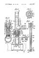
- FIG. 2is an enlarged elevation view of a combination of the blood access device of FIG. 1 with an adaptor and extractor;
- FIG. 3is a fragmentary elevation view of the extractor of FIG. 2 shown engaged with the plug;
- FIG. 4is an enlarged fragmentary sectional view taken generally along the line 4--4 of FIG. 2 of the adaptor linked to the plug-containing blood access device;
- FIG. 5is a sectional view taken generally along the line 5--5 of FIG. 4 illustrating withdrawal movement of the plug to an upper position within the adaptor;
- FIG. 6is a sectional view of the lower end of the extractor taken along lines 6--6 of FIG. 3;
- FIG. 7is an enlarged sectional view taken along line 7--7 of FIG. 4;
- FIG. 8is a cross-sectional view of the cap shown in FIG. 1;
- FIG. 8ais a perspective view illustrating an alternative insertion of the blood access device into a blood vessel.
- FIG. 9is an elevation view, partially cut away and partially in section, of an alternative embodiment of an access device adapted to provide access to the peritoneum.
- FIG. 1illustrates a blood access device 10 including a tubular conduit 12 which has been inserted into the circulatory system of the living body and an access tube 14 which is integral with the conduit 12 and extends above the skin to provide a first blood passageway 15 (FIG. 5).
- the blood access device 10is sealed by a cap 16.
- the conduit 12is in fluid communication with the access tube 14. Blood flow through the first passageway 15 to the exposed end 22 of the access tube 14 is blocked by a removable plug 24.
- the cap 16When blood access is desired, the cap 16 is removed from the access device 10 and an adaptor 26 (FIGS. 2 and 5) is fitted on to the exposed end 22 of the blood access device 10 to communicate therewith.
- the adaptor 26consists of a main tube 28 with a lower end 30 attachable to the access tube 14, an open upper end 31 and a blood outlet or side tube 32 having an open end 34 for communication with external devices. (To aid description, “lower” is herein used to denote the direction toward the interior of the body and “upper” is used to describe the direction toward the exterior of the body).
- An extractor 40(FIGS. 2, 3 and 6) is provided that contains a small diameter lower gripping portion 42 which may be inserted into the upper end 31 of the adaptor 26 and through the entire length of the main tube 28 so that a latching means 44 may reversibly engage with a cooperating latching member 46 at the top of the plug 24.
- the plug 24When the plug 24 is engaged with the extractor 40, the plug 24 may be pulled from the access tube 14 through the adaptor 26 to a blood access position above the side tube 32 establishing communication between the conduit 12 and the side tube 32, so that blood may flow from a blood vessel to an external device attached to the side tube 32.
- the conduit 12 of the blood access device 10(FIGS. 4 and 5) is generally cylindrical in shape with a smooth cylindrical central passageway 48 for unhindered blood flow.
- the access device(FIG. 1) in a blood vessel
- the blood vesselis severed and the severed ends 49 are attached at each end of the conduit 12 by conventional means, such as by suturing. Ridges 52 on the exterior of the conduit 12 provide for a more secure union between the blood vessel ends 49 and the conduit 12.
- the blood vessel 49is opened with a longitudinal slit 50, the conduit 12 inserted through the slit and the slit closed around the access tube 14 by sutures 53.
- the devicemay be incorporated in a vascular graft formed of woven or non-woven fabric, e.g., non-woven fabric sold under the trade name Gore-tex.
- a vascular graftformed of woven or non-woven fabric, e.g., non-woven fabric sold under the trade name Gore-tex.
- Such a graftmay be used as a shunt between a blood vessel and an artery.
- the access tube 14communicates with the conduit 12 through an orifice 56 which has a diameter slightly less than the interior diameter of the access tube 14 preventing the plug 24 from being pushed downward into the conduit 12 yet providing ample passageway for blood when the plug 24 is removed.
- An annular male threaded member 59 for linking the blood access device 10 either to the adaptor 26 or to the cap 16extends from the upper end of the access tube 14.
- the threaded member 59has an interior diameter larger than the access tube 14, for reasons which will be clarified hereinafter, and is integrally joined to the access tube 14 by an annular shoulder 58.
- the plug 24slides upward and downward within the access tube and the adaptor 26.
- a resilient annular sealing member 66blocks blood flow therearound.
- the sealing member 66has an outer diameter substantially equal to or slightly larger than the interior diameter of the access tube 14 so that the sealing member 66 abuts the interior wall 65 of the access tube and seals therewith.
- a bore 68 through the sealing memberfacilitates its attachment to the body of the plug 24, as hereinafter described.
- the body of the plug 24comprises a narrow tubular portion 69 which abuts the sealing member 66 at the lower end and terminates at the upper end in a larger tubular portion 70 of diameter substantially equal to the interior diameter of the access tube 14.
- a frustoconical shoulder 67integrally connects the narrow and larger tubular portions 69 and 70 of the plug 24.
- the distance between the front of the sealing member 66 and the top of the frustoconical shoulder 67is slightly shorter than the first passageway 15 so that when the plug 24 is fully inserted in the access tube 14, the larger tubular section 70 of the plug 24 extends slightly into the access tube 14 to provide lateral stability of the plug within the passageway 15.
- a connector 72consisting of an upper pipe 74 which terminates in a lower head 76, secures the sealing member 66 to the body of the plug 24.
- the connector head 76which is larger in diameter than both the pipe 74 and the bore 68 through the annular sealing member 66 has an upper flat side 77 from which the pipe 74 extends and a lower rounded side 78.
- the pipe 74with an exterior diameter substantially equal to the interior diameter of the narrow tubular portion 69 of the plug 24, extends from the head 76, through the bore 68 in the sealing member 66, through the bore 79 of the narrow tubular portion 69, and into an enlarged-in-diameter portion 80 thereof where a snap ring 81 is located in an annular groove 82 in the end of the pipe 74.
- the annular groove 82is appropriately spaced from the head 76 so that, when the snap ring 81 is in place, it abuts the lower end 83 of the enlarged portion 80, and the flat side 77 of the connector head 76 abuts the lower surface of the sealing member 66 and blocks fluid passage through the bore 68.
- Channel meansare provided so that surfaces of the plug 24 and surfaces of the access tube 14 above the sealing member 66, which may become coated with blood, may be cleaned by flushing when the plug is located in a blocking position in the access tube 10. Openings in the wall of pipe 74 are aligned with openings 94 in the narrow tubular portion 69 of the plug 24. The openings 94 and 96 provide communication between the center channel 97 of the pipe 74 with an annular vacant region 100 between the narrow tubular portion 69 of the plug 24 and the interior wall 65 of the access tube 14. A pair of orifices 101 are provided in the frustoconical shoulder 67 to provide communication between the annular region 100 and the interior of the larger tubular portion 70.
- cleaning solutionis injected into the center channel 97 of the pipe 24 after the plug has been returned to the blocking position.
- the solutionflows through the openings 94 and 96, upward in the annular region 100 and out through the orifices 101 in the frusto conical shoulder 67.
- a linking means 102comprised of a female threaded member 103 which cooperates with the male threaded member 59 of the access tube 14 to join the adaptor 26 to the access tube 14.
- Concentric with the female threaded memberis a smaller-in-diameter annular skirt 104 having an interior wall 105 which is a continuation of the interior wall 106 of the main tube 28 of the adaptor 26.
- the exterior wall 107 of the skirt 104 and interior wall 108 of the male member 59are frustoconical, being of greater diameter at their respective upper ends.
- the skirt 104 of the adaptor 24extends generally to the shoulder 58 of the access device 10, and the outer and inner frustoconical walls 107, 108 abut to form a fluid-tight seal.
- the second passageway 110 provided by the main tube 28 of the adaptor 26coaxially aligns with the first passageway 15 of the access device 10 to form a continuous passageway of substantially uniform diameter through which the plug 24 may be relocated with the sealing member 66 at all times preventing fluid flow therearound.
- the main tube 28 of the adaptor 26extends sufficiently above the side tube 32 providing a chamber portion 113 to receive the plug 24 when it is withdrawn from its blocking position within the access tube.
- the sealing member 66is above the side tube 32 to allow fluid to flow from the conduit 12 out through the side tube.
- an annular ring 111 integral with the interior wall 106 of the adaptorextends inward therefrom to limit upward movement of the plug 24 so that the plug may not accidentally be pulled from the open upper end of the adaptor.
- the exterior of the side arm 32preferably has ridges 112 for securely retaining flexible tubing (not shown).
- the interior diameter of the side arm 32is preferrably generally equal to the interior diameter of the main tube 28 to permit maximum blood flow therethrough.
- Suitable meanssuch as threads, a bayonet fitting or hooks are employed to latch the extractor 40 to the upper end of the plug 24.
- the latching means 44 of the extractor 40comprises a ball lock which reversibly engages the cooperating latching member 46 in the form of an annular groove 138 in the interior wall 139 of the wider tubular portion 70 of the plug 24.
- the ball lockwhich allows for quick gripping and quick releasing of the plug 24 by the extractor 40, is included near the lower end of the extractor.
- the gripping portion 42fits through the upper open end 31 of the adaptor 26 to grip the plug 24 after the adaptor 26 has been joined to the access device 10 and includes a tubular lower section 122 wherein a rod 124 is slidably disposed.
- the lower end of the rod 124is necked down to form a frustoconical camming surface 140 and terminates in a narrow tip 142.
- a hollow 144is formed in the sidewall of the tube 122 which holds a ball 146 of diameter slightly greater than the dimension of the exterior entrance to the hollow 144.
- the hollow 144aligns with the annular groove 138 in the interior wall 139 of the wider tubular portion 70 of the adaptor 26.
- the ball 146is cammed outward by the camming surface 140 until it is locked in this outward position by the surface of the rod 124 with the ball 146 extending partially through the entrance of the hollow 144 and into the annular groove 130 in the plug 24 with which it is thus mated.
- the ball lockis activated by a plunger mechanism 160 in which a plunger 166 is biased outward of a plunger body 162 into a non-actuating position by a helical spring 167 and which may be displaced to an actuating positon by depression of the plunger. Depression of the plunger 166, which is accomplished by gripping a handle portion 180 of the plunger body while pushing downward a knob portion 182 at the upper end of the plunger, slides the rod 124, to which the plunger is integrally connected, downward through the lower tubular section 122.
- the upward or non-actuating position and the lower or non-actuating positions of the plunger 166are defined by the lower and upper walls 171, 172 of a vertical plunger slot 168 abutting a boss 169 extending inward of the plunger body 162.
- the userAfter screwing the adaptor 26 to the access device 10 and connecting the side tube 32 of the adaptor to an external device, the user inserts the extractor 40 until the shoulder 164 of the extractor abuts the upper end 31 of the adaptor.
- the userdepresses the plunger 160 to activate the ball lock to grip the plug 24.
- the userpulls the extractor 40 upward until the plug 24 abuts the annular ring 111 at the upper end 31 of the adaptor 26.
- the plugWith the plug in the withdrawn position at which the sealing member 66 is located outward of the side tube 32, blood flows from the conduit 12 through the side tube.
- the plunger 160is thereafter released, unlocking the ball 146, and the extractor 40 is removed.
- the pressure of the sealing member 66 against the interior wall 106 of the adaptor 26maintains the plug 24 in its withdrawn position until it is pushed inward.
- the extractor 40is reinserted, the plunger 160 is depressed and the plug 24 is pushed fully down into the blocking position within the access tube 14 to reseal the first passageway 15.
- the adaptor 26is unscrewed, and the access device 10 is washed and recapped.
- the cap 16is applied to the blood access device in a manner identical to application of the adaptor 26.
- the cap 16has a circular top 261 with a threaded outer skirt 264 and a concentric inner skirt 263 depending therefrom.
- the inner skirthas a frustoconical exterior surface 265 to seal with the frustoconical interior 108 surface of the male member 59 of the access device 10 so that a disinfectant solution may be contained therein between times when blood access is desired.
- the blood access device 10is designed for generally permanent implantation in the human body and is strong and durable. The surfaces should be biocompatible and thromboresistant.
- the device 10may be made of metals, e.g., titanium, stainless steel and chromium-cobalt alloys, such as those sold under the trade name Vitallium.
- the sealing member 66 of the plug 24is made of resilient material, such as silicone rubber.
- the remaining componentsmay be made of any suitably strong and durable material provided that surfaces which contact blood are thromboresistant.
- Surfacesmay be made biocompatible and thromboresistant by coating them with carbon, i.e., by vapor deposition as described in U.S. Pat. No. 3,952,336 issued Apr. 27, 1976 to Bokros, et al.
- the blood passagewayincludes the entire interior diameter of the housing 10, a feature not available in valve type blood access devices. This diameter is continued through the second passageway 110 of the adaptor 26 and through the side tube 32 so that a maximum blood flow is obtained from a small blood access device.
- the plug 24which sits in the access tube 14 has no moving parts, and should any part of the plug 24 show signs of wearing out, the plug itself could be easily replaced simply by applying a tourniquet to the arm to prevent significant loss of blood, quickly pulling out the old plug and inserting a new one.
- the adaptor 26 and extractor 40being devices external to the body, can be replaced or repaired at will. All surfaces of the blood access device 10 and plug 24, which contact blood and are disposed above the sealing member 66, are easily washable, and a disinfectant solution may be sealed in the access tube 14 by the cap 16 to prevent bacterial growth and possible infection. Furthermore, the sealing member 66 rubs against the inner surface of the passage 15 as the plug 24 is inserted and extracted, thereby wiping the inner surface to help keep it clean.
- FIG. 9Illustrated in FIG. 9 is an assembly including an internal access device 300 adapted for insertion into a living body to provide communication to a fluid-containing body cavity, in particular the peritoneum, through the rib cage rather than directly through the abdomen. Access through the rib cage permits anchoring of the device to one of the rib bones and passage of the device through the relatively stationary soft tissue overlying the ribs rather than through the continually moving soft tissue covering the abdomen to permit greater activity of the patient without risk of dislodging the device.
- an internal access device 300adapted for insertion into a living body to provide communication to a fluid-containing body cavity, in particular the peritoneum, through the rib cage rather than directly through the abdomen.
- Access through the rib cagepermits anchoring of the device to one of the rib bones and passage of the device through the relatively stationary soft tissue overlying the ribs rather than through the continually moving soft tissue covering the abdomen to permit greater activity of the patient without risk of dislodging the device.
- the internal access device 300provides a passageway 302 to the peritoneum, and a plug 304 closes the outer end of the passageway.
- An extraction device 306is used to withdraw the plug from the passageway into an adaptor 308 that connects the peritoneum passageway to appropriate external apparatus.
- the extractor 306 and the "T" shaped adaptor 308are substantially as described hereinabove in reference to the blood access device, with appropriate adjustment in size to provide for an appropriate passageway as required for peritoneal access devices.
- the plug 304likewise is similar to that described hereinabove in reference to the blood access device providing a surrounding vacant region 309 within the passageway 302 and having a fluid passageway network 310 above a sealing member 312 to permit cleaning of surfaces of the plug and passageway.
- the access device 300includes the access tube 318 and an outer sleeve 314 having an inner flange portion 315 by which the device is anchored to a rib bone 316.
- the sleeve 314is proportioned to extend above the skin when the flange 315 is anchored to the bone.
- the sleeveis preferably formed of graphite coated with pyrolytic carbon, such as that sold under the tradename Pyrolite.
- the sleevemay also be formed of a metal, such as titanium which is compatible with body tissues; the surfaces which contact soft tissue are preferably coated with pyrolytic carbon.
- the surfaces which contact soft tissuesmay be covered with a fabric layer which promotes the ingrowth of tissue and possibly coated with vapor-deposited carbon, such as that sold under the tradename Biolite.
- the flange 315which typically has a diameter between about two and about three times the outside diameter of the outer portions of the sleeve 314, has a bone contact surface 326 formed with indentations or pores 328, and a cement containing hydroxyapatite (HA) or an HA coating can be used to attach the porous surface to the bone.
- HAhydroxyapatite
- the rigid access tube 318which receive the plug 304, is held in a bore 326 which extends through the sleeve 314.
- the tube 318is held in the bore with an adhesive, or alternatively, the sleeve 314 is shrink-fitted around the rigid tube.
- the outer end of the access tube 318extends above the upper end of the sleeve 314 and has a male fitting 330, substantially as described hereinabove in reference to the blood access device, for alternate attachment to the adaptor 308 or a covering cap (not shown).
- the opposite end of the access tube 318extends inward of the flange 315 and substantially through a circular opening 325 surgically formed in the rib bone 316.
- the flexible tube 320which extends from the rib bone 316 to the peritoneum 321, is formed of a biocompatible polymeric material, such as silicone rubber or polyurethane. Its outside diameter is matched to that of an enlarged-in-diameter inner portion 328 of the sleeve bore 327 while its inside diameter is matched to outside diameter of the access tube 318.
- the flexible tubeextends through the bore in the bone, around the lower end of the rigid tube 318 and is received in an annular area 334 of the enlarged-in-diameter bore portion 328 around the rigid tube.
- the outer end of the flexible tube 320is adhesive-bonded or heat-bonded to the sleeve 314 and access tube 318 assuring permanent attachment thereto.
- the inner end of the flexible tubeis open and extends through the peritoneum wall 336.
- the flexible tubecarries a cuff 338 for suturing to an opening surgically formed in the peritoneum wall.
- the cuff 338is formed of dacron velour or another open weave fabric which promotes ingrowth of tissue into the fabric, and the fabric is preferably coated with vapor-deposited carbon giving the cuff excellent biocompatible properties.
- the members of the access device 300are preassembled to facilitate insertion during a surgical procedure.
- the bore 325is formed in a lower rib, the inner end of the flexible tube 320 extended into the peritoneum, the cuff 338 sutured the peritonial wall and the flange 315 anchored to the rib bone.
- the implanted access device 300is carried without sigificant irritation to the user as the rib bone and overlying tissue are generally stationary relative to each other during normal activities.
- the flexible tubing, which bypasses the diaphragm,is substantially unfelt in place.
- the access deviceis implanted in a part of the body readily accessable to the patient allowing the patient to attach the adaptor and external support systems to the access device for self-treatment.
Landscapes
- Health & Medical Sciences (AREA)
- Heart & Thoracic Surgery (AREA)
- Life Sciences & Earth Sciences (AREA)
- Engineering & Computer Science (AREA)
- Gastroenterology & Hepatology (AREA)
- Pulmonology (AREA)
- Biophysics (AREA)
- Anesthesiology (AREA)
- Biomedical Technology (AREA)
- Hematology (AREA)
- Animal Behavior & Ethology (AREA)
- General Health & Medical Sciences (AREA)
- Public Health (AREA)
- Veterinary Medicine (AREA)
- External Artificial Organs (AREA)
Abstract
Description
Claims (20)
Priority Applications (4)
| Application Number | Priority Date | Filing Date | Title |
|---|---|---|---|
| US06/324,040US4421507A (en) | 1980-12-24 | 1981-11-23 | Plug-type fluid access devices |
| CA000392221ACA1167343A (en) | 1980-12-24 | 1981-12-14 | Plug-type fluid access devices |
| DE8181305954TDE3171857D1 (en) | 1980-12-24 | 1981-12-18 | Plug-type percutaneous access device for fluids |
| EP81305954AEP0063198B1 (en) | 1980-12-24 | 1981-12-18 | Plug-type percutaneous access device for fluids |
Applications Claiming Priority (2)
| Application Number | Priority Date | Filing Date | Title |
|---|---|---|---|
| US22010180A | 1980-12-24 | 1980-12-24 | |
| US06/324,040US4421507A (en) | 1980-12-24 | 1981-11-23 | Plug-type fluid access devices |
Related Parent Applications (1)
| Application Number | Title | Priority Date | Filing Date |
|---|---|---|---|
| US22010180AContinuation-In-Part | 1980-12-24 | 1980-12-24 |
Publications (1)
| Publication Number | Publication Date |
|---|---|
| US4421507Atrue US4421507A (en) | 1983-12-20 |
Family
ID=26914569
Family Applications (1)
| Application Number | Title | Priority Date | Filing Date |
|---|---|---|---|
| US06/324,040Expired - Fee RelatedUS4421507A (en) | 1980-12-24 | 1981-11-23 | Plug-type fluid access devices |
Country Status (4)
| Country | Link |
|---|---|
| US (1) | US4421507A (en) |
| EP (1) | EP0063198B1 (en) |
| CA (1) | CA1167343A (en) |
| DE (1) | DE3171857D1 (en) |
Cited By (26)
| Publication number | Priority date | Publication date | Assignee | Title |
|---|---|---|---|---|
| US4496350A (en)* | 1980-04-08 | 1985-01-29 | Renal Systems, Inc. | Blood access device |
| US4639247A (en)* | 1984-11-02 | 1987-01-27 | Carbomedics, Inc. | Percutaneous access device |
| US4654033A (en)* | 1984-04-02 | 1987-03-31 | Biomasys | Device for atraumatic access to the blood circuit |
| US4790826A (en)* | 1986-03-28 | 1988-12-13 | Elftman Nancy W | Percutaneous access port |
| US5084151A (en)* | 1985-11-26 | 1992-01-28 | Sorin Biomedica S.P.A. | Method and apparatus for forming prosthetic device having a biocompatible carbon film thereon |
| US5370684A (en)* | 1986-12-12 | 1994-12-06 | Sorin Biomedica S.P.A. | Prosthesis of polymeric material coated with biocompatible carbon |
| WO1995000188A1 (en)* | 1993-06-28 | 1995-01-05 | Maximwell International Co., (U.S.A.) Ltd. | Multishot sidearm injection device |
| US5387247A (en)* | 1983-10-25 | 1995-02-07 | Sorin Biomedia S.P.A. | Prosthetic device having a biocompatible carbon film thereon and a method of and apparatus for forming such device |
| US5421814A (en)* | 1993-06-03 | 1995-06-06 | Innovations For Access, Inc. | Hemodialysis infusion port and access needle |
| US5807356A (en)* | 1994-01-18 | 1998-09-15 | Vasca, Inc. | Catheter with valve |
| US6042569A (en)* | 1994-01-18 | 2000-03-28 | Vasca, Inc. | Subcutaneously implanted cannula and methods for vascular access |
| US6053901A (en)* | 1994-01-18 | 2000-04-25 | Vasca, Inc. | Subcutaneously implanted cannula and method for arterial access |
| US6261257B1 (en) | 1998-05-26 | 2001-07-17 | Renan P. Uflacker | Dialysis graft system with self-sealing access ports |
| US6355020B1 (en)* | 1995-07-07 | 2002-03-12 | Gerald G. Bousquet | Transcutaneous access device |
| US20040019315A1 (en)* | 2000-01-11 | 2004-01-29 | Blatter Duane D. | Apparatus and methods for facilitating repeated vascular access |
| US6722705B2 (en)* | 2002-04-25 | 2004-04-20 | Ab Korkor Medical, Inc. | Medical tubing connector |
| US20040147866A1 (en)* | 2003-01-23 | 2004-07-29 | Blatter Duane D. | Apparatus and methods for occluding an access tube anastomosed to sidewall of an anatomical vessel |
| US7124570B2 (en)* | 2003-01-23 | 2006-10-24 | Integrated Vascular Interventional Technologies, L.C. | Apparatus and methods for fluid occlusion of an access tube anastomosed to an anatomical vessel |
| US20070073250A1 (en)* | 2005-07-08 | 2007-03-29 | Schneiter James A | Implantable port |
| US20070270766A1 (en)* | 2006-05-18 | 2007-11-22 | Cannuflow, Inc. | Anti-extravasation surgical portal plug |
| WO2009059371A3 (en)* | 2007-11-07 | 2009-07-09 | Rodney James Lane | Systems, methods and devices for circulatory access |
| EP2286849A1 (en)* | 2009-08-21 | 2011-02-23 | Cendres & Métaux S.A. | Implantable vascular access |
| US20110282303A1 (en)* | 2009-01-22 | 2011-11-17 | V. Krutten Medizinische Einmalgerate GmbH | Device for feeding medical fluids |
| EP2859911A1 (en) | 2013-10-11 | 2015-04-15 | qSTAR Medical SAS | Vascular access port devices with incorporated sensors |
| US11607323B2 (en) | 2018-10-15 | 2023-03-21 | Howmedica Osteonics Corp. | Patellofemoral trial extractor |
| US20250073433A1 (en)* | 2023-12-21 | 2025-03-06 | Yanshan University | Pressure control valve for blood system and its pressure regulation method |
Families Citing this family (6)
| Publication number | Priority date | Publication date | Assignee | Title |
|---|---|---|---|---|
| US4488877A (en)* | 1982-08-23 | 1984-12-18 | Renal Systems, Inc. | Percutaneous implant for peritoneal dialysis |
| FR2598312B1 (en)* | 1986-05-07 | 1989-09-29 | Vincent Bouton | PERMANENT TRANS-NASAL SINUSIAN AERATOR IN DOUBLE "T" |
| US4964850A (en)* | 1986-05-07 | 1990-10-23 | Vincent Bouton | Method for treating trans-nasal sinus afflictions using a double t-shaped trans-nasal aerator |
| WO1989001350A1 (en)* | 1987-08-19 | 1989-02-23 | Olle Berg | A drainage tube for sinus maxillaris, a means for its insertion and a means for making a hole for its positioning |
| SE505552C2 (en)* | 1995-12-22 | 1997-09-15 | Atos Medical Ab | Method for mounting a flanged tubular body |
| EP1791586B1 (en)* | 2004-09-07 | 2014-01-15 | Droneon Pty Limited | Peripheral access devices and systems |
Citations (8)
| Publication number | Priority date | Publication date | Assignee | Title |
|---|---|---|---|---|
| US3765032A (en)* | 1972-09-27 | 1973-10-16 | J Palma | Implant |
| US3826257A (en)* | 1972-07-14 | 1974-07-30 | T Buselmeier | Prosthetic shunt |
| US3998222A (en)* | 1974-04-15 | 1976-12-21 | Shihata Alfred A | Subcutaneous arterio-venous shunt with valve |
| US4015601A (en)* | 1975-10-14 | 1977-04-05 | General Atomic Company | Blood access device |
| US4108173A (en)* | 1977-04-11 | 1978-08-22 | General Atomic Company | Blood access device |
| US4108174A (en)* | 1977-01-31 | 1978-08-22 | General Atomic Company | Catheter interlock system |
| US4164221A (en)* | 1977-07-28 | 1979-08-14 | Bentley Laboratories, Inc. | Atraumatic blood access device valve |
| US4349021A (en)* | 1980-06-09 | 1982-09-14 | Bentley Laboratories | Atraumatic blood access device valve |
Family Cites Families (1)
| Publication number | Priority date | Publication date | Assignee | Title |
|---|---|---|---|---|
| DE2948949A1 (en)* | 1979-08-15 | 1981-03-26 | American Hospital Supply Corp., Evanston, Ill. | IMPLANTATION ELEMENT |
- 1981
- 1981-11-23USUS06/324,040patent/US4421507A/ennot_activeExpired - Fee Related
- 1981-12-14CACA000392221Apatent/CA1167343A/ennot_activeExpired
- 1981-12-18DEDE8181305954Tpatent/DE3171857D1/ennot_activeExpired
- 1981-12-18EPEP81305954Apatent/EP0063198B1/ennot_activeExpired
Patent Citations (8)
| Publication number | Priority date | Publication date | Assignee | Title |
|---|---|---|---|---|
| US3826257A (en)* | 1972-07-14 | 1974-07-30 | T Buselmeier | Prosthetic shunt |
| US3765032A (en)* | 1972-09-27 | 1973-10-16 | J Palma | Implant |
| US3998222A (en)* | 1974-04-15 | 1976-12-21 | Shihata Alfred A | Subcutaneous arterio-venous shunt with valve |
| US4015601A (en)* | 1975-10-14 | 1977-04-05 | General Atomic Company | Blood access device |
| US4108174A (en)* | 1977-01-31 | 1978-08-22 | General Atomic Company | Catheter interlock system |
| US4108173A (en)* | 1977-04-11 | 1978-08-22 | General Atomic Company | Blood access device |
| US4164221A (en)* | 1977-07-28 | 1979-08-14 | Bentley Laboratories, Inc. | Atraumatic blood access device valve |
| US4349021A (en)* | 1980-06-09 | 1982-09-14 | Bentley Laboratories | Atraumatic blood access device valve |
Cited By (36)
| Publication number | Priority date | Publication date | Assignee | Title |
|---|---|---|---|---|
| US4496350A (en)* | 1980-04-08 | 1985-01-29 | Renal Systems, Inc. | Blood access device |
| US5387247A (en)* | 1983-10-25 | 1995-02-07 | Sorin Biomedia S.P.A. | Prosthetic device having a biocompatible carbon film thereon and a method of and apparatus for forming such device |
| US4654033A (en)* | 1984-04-02 | 1987-03-31 | Biomasys | Device for atraumatic access to the blood circuit |
| US4639247A (en)* | 1984-11-02 | 1987-01-27 | Carbomedics, Inc. | Percutaneous access device |
| US5084151A (en)* | 1985-11-26 | 1992-01-28 | Sorin Biomedica S.P.A. | Method and apparatus for forming prosthetic device having a biocompatible carbon film thereon |
| US4790826A (en)* | 1986-03-28 | 1988-12-13 | Elftman Nancy W | Percutaneous access port |
| US5370684A (en)* | 1986-12-12 | 1994-12-06 | Sorin Biomedica S.P.A. | Prosthesis of polymeric material coated with biocompatible carbon |
| US5421814A (en)* | 1993-06-03 | 1995-06-06 | Innovations For Access, Inc. | Hemodialysis infusion port and access needle |
| WO1995000188A1 (en)* | 1993-06-28 | 1995-01-05 | Maximwell International Co., (U.S.A.) Ltd. | Multishot sidearm injection device |
| US5807356A (en)* | 1994-01-18 | 1998-09-15 | Vasca, Inc. | Catheter with valve |
| US6042569A (en)* | 1994-01-18 | 2000-03-28 | Vasca, Inc. | Subcutaneously implanted cannula and methods for vascular access |
| US6053901A (en)* | 1994-01-18 | 2000-04-25 | Vasca, Inc. | Subcutaneously implanted cannula and method for arterial access |
| US6398764B1 (en) | 1994-01-18 | 2002-06-04 | Vasca. Inc. | Subcutaneously implanted cannula and method for arterial access |
| US6355020B1 (en)* | 1995-07-07 | 2002-03-12 | Gerald G. Bousquet | Transcutaneous access device |
| US6261257B1 (en) | 1998-05-26 | 2001-07-17 | Renan P. Uflacker | Dialysis graft system with self-sealing access ports |
| US7118546B2 (en)* | 2000-01-11 | 2006-10-10 | Integrated Vascular Interventional Technologies, L.C. | Apparatus and methods for facilitating repeated vascular access |
| US20040019315A1 (en)* | 2000-01-11 | 2004-01-29 | Blatter Duane D. | Apparatus and methods for facilitating repeated vascular access |
| US6722705B2 (en)* | 2002-04-25 | 2004-04-20 | Ab Korkor Medical, Inc. | Medical tubing connector |
| US20040147866A1 (en)* | 2003-01-23 | 2004-07-29 | Blatter Duane D. | Apparatus and methods for occluding an access tube anastomosed to sidewall of an anatomical vessel |
| US7124570B2 (en)* | 2003-01-23 | 2006-10-24 | Integrated Vascular Interventional Technologies, L.C. | Apparatus and methods for fluid occlusion of an access tube anastomosed to an anatomical vessel |
| US7131959B2 (en) | 2003-01-23 | 2006-11-07 | Integrated Vascular Interventional Technologies, L.C., (“IVIT LC”) | Apparatus and methods for occluding an access tube anastomosed to sidewall of an anatomical vessel |
| US20070073250A1 (en)* | 2005-07-08 | 2007-03-29 | Schneiter James A | Implantable port |
| US20070270766A1 (en)* | 2006-05-18 | 2007-11-22 | Cannuflow, Inc. | Anti-extravasation surgical portal plug |
| US8652090B2 (en)* | 2006-05-18 | 2014-02-18 | Cannuflow, Inc. | Anti-extravasation surgical portal plug |
| WO2009059371A3 (en)* | 2007-11-07 | 2009-07-09 | Rodney James Lane | Systems, methods and devices for circulatory access |
| US9078982B2 (en) | 2007-11-07 | 2015-07-14 | Rodney J. Lane | Systems, methods and devices for circulatory access |
| US20110282303A1 (en)* | 2009-01-22 | 2011-11-17 | V. Krutten Medizinische Einmalgerate GmbH | Device for feeding medical fluids |
| US8702661B2 (en)* | 2009-01-22 | 2014-04-22 | V. Krutten Medizinische Einmalgerate GmbH | Device for feeding medical fluids |
| CN102548591A (en)* | 2009-08-21 | 2012-07-04 | 灰+金属有限公司 | Implantable vascular access |
| WO2011020873A1 (en)* | 2009-08-21 | 2011-02-24 | Cendres + Métaux Sa | Implantable vascular access |
| CN102548591B (en)* | 2009-08-21 | 2014-09-17 | 灰+金属有限公司 | Implantable vascular access |
| US8926591B2 (en) | 2009-08-21 | 2015-01-06 | Cendres + Metaux Sa | Implantable vascular access |
| EP2286849A1 (en)* | 2009-08-21 | 2011-02-23 | Cendres & Métaux S.A. | Implantable vascular access |
| EP2859911A1 (en) | 2013-10-11 | 2015-04-15 | qSTAR Medical SAS | Vascular access port devices with incorporated sensors |
| US11607323B2 (en) | 2018-10-15 | 2023-03-21 | Howmedica Osteonics Corp. | Patellofemoral trial extractor |
| US20250073433A1 (en)* | 2023-12-21 | 2025-03-06 | Yanshan University | Pressure control valve for blood system and its pressure regulation method |
Also Published As
| Publication number | Publication date |
|---|---|
| CA1167343A (en) | 1984-05-15 |
| EP0063198B1 (en) | 1985-08-14 |
| EP0063198A1 (en) | 1982-10-27 |
| DE3171857D1 (en) | 1985-09-19 |
Similar Documents
| Publication | Publication Date | Title |
|---|---|---|
| US4421507A (en) | Plug-type fluid access devices | |
| US4425119A (en) | Implantable device for intravascular access | |
| US4781693A (en) | Insulin dispenser for peritoneal cavity | |
| US4496349A (en) | Percutaneous implant | |
| US4488877A (en) | Percutaneous implant for peritoneal dialysis | |
| US4496350A (en) | Blood access device | |
| US4417888A (en) | Percutaneous implant | |
| JP5529541B2 (en) | Nervous system device with percutaneous access device | |
| US7678101B2 (en) | Locking catheter connector and connection system | |
| US3633585A (en) | Catheter | |
| US5906596A (en) | Percutaneous access device | |
| US6997914B2 (en) | Implantable access port | |
| US4874377A (en) | Self-occluding intravascular cannula assembly | |
| US5360397A (en) | Hemodiaylsis catheter and catheter assembly | |
| EP0809523B1 (en) | Implantable access device | |
| GB2050175A (en) | Atraumatic valving mechanisms | |
| JPH0326273A (en) | Reservoir for ventricular fistula formation | |
| US7837646B2 (en) | Hydrocephalus shunt system quick connector assembly | |
| EP0143517B1 (en) | Implantable parenteral hyperalimentation catheter system | |
| EP1765456A1 (en) | Multi-functional port | |
| US4349021A (en) | Atraumatic blood access device valve | |
| US20210316126A1 (en) | Seal | |
| US20190308004A1 (en) | Low profile self-sealing access port | |
| JPH0339694B2 (en) | ||
| JP2004195203A (en) | Non-puncture blood access for hemodialysis |
Legal Events
| Date | Code | Title | Description |
|---|---|---|---|
| AS | Assignment | Owner name:CARBOMEDICS, INC., 1300 EAST ANDERSON LANE, AUSTIN Free format text:ASSIGNMENT OF ASSIGNORS INTEREST.;ASSIGNOR:BOKROS, JACK C.;REEL/FRAME:003955/0385 Effective date:19811113 Owner name:CARBOMEDICS, INC., A CORP. OF TEX., TEXAS Free format text:ASSIGNMENT OF ASSIGNORS INTEREST;ASSIGNOR:BOKROS, JACK C.;REEL/FRAME:003955/0385 Effective date:19811113 | |
| AS | Assignment | Owner name:BRAZOSPORT BANK OF TEXAS Free format text:SECURITY INTEREST;ASSIGNORS:INTERMEDICS, INC.;INTERMEDICS CARDIASSIST, INC.;INTERMEDICS INTRAOCULAR, INC.;AND OTHERS;REEL/FRAME:004303/0077 Effective date:19840726 Owner name:FIRST FREEPORT NATIONAL BANK Free format text:SECURITY INTEREST;ASSIGNORS:INTERMEDICS, INC.;INTERMEDICS CARDIASSIST, INC.;INTERMEDICS INTRAOCULAR, INC.;AND OTHERS;REEL/FRAME:004303/0077 Effective date:19840726 Owner name:CITIBANK, N.A., AS AGENT Free format text:SECURITY INTEREST;ASSIGNORS:INTERMEDICS, INC.;INTERMEDICS CARDIASSIST, INC.;INTERMEDICS INTRAOCULAR, INC.;AND OTHERS;REEL/FRAME:004303/0077 Effective date:19840726 Owner name:CHASE MANHATTAN BANK, N.A., THE Free format text:SECURITY INTEREST;ASSIGNORS:INTERMEDICS, INC.;INTERMEDICS CARDIASSIST, INC.;INTERMEDICS INTRAOCULAR, INC.;AND OTHERS;REEL/FRAME:004303/0077 Effective date:19840726 Owner name:FIRST NATIONAL BANK OF CHICAGO, THE Free format text:SECURITY INTEREST;ASSIGNORS:INTERMEDICS, INC.;INTERMEDICS CARDIASSIST, INC.;INTERMEDICS INTRAOCULAR, INC.;AND OTHERS;REEL/FRAME:004303/0077 Effective date:19840726 Owner name:TRUST COMPANY BANK Free format text:SECURITY INTEREST;ASSIGNORS:INTERMEDICS, INC.;INTERMEDICS CARDIASSIST, INC.;INTERMEDICS INTRAOCULAR, INC.;AND OTHERS;REEL/FRAME:004303/0077 Effective date:19840726 Owner name:BANK OF AMERICA NATIONAL TRUST AND SAVINGS ASSOCIA Free format text:SECURITY INTEREST;ASSIGNORS:INTERMEDICS, INC.;INTERMEDICS CARDIASSIST, INC.;INTERMEDICS INTRAOCULAR, INC.;AND OTHERS;REEL/FRAME:004303/0077 Effective date:19840726 | |
| AS | Assignment | Owner name:CITIBANK, N.A. Free format text:SECURITY INTEREST;ASSIGNORS:INTERMEDICS, INC., A TX CORP;INTERMEDICS CARDIASSIST, INC., A TX CORP.;INTERMEDICS INTRAOCULAR, INC., A TX CORP.;AND OTHERS;REEL/FRAME:004434/0728 Effective date:19850703 Owner name:B.A. LEASING CORPORATION Free format text:SECURITY INTEREST;ASSIGNORS:INTERMEDICS, INC., A CORP. OF TEXAS;INTERMEDICS CARDIASSIST, INC.;INTERMEDICS INTRAOCULAR, INC., A CORP. OF TEXAS;AND OTHERS;REEL/FRAME:004449/0424 Effective date:19850703 Owner name:CITICORP MILTILEASE (SEF), INC. Free format text:SECURITY INTEREST;ASSIGNORS:INTERMEDICS, INC.;INTERMEDICS CARDIASSIST, INC.;INTERMEDICS INTRAOCULAR, INC., A CORP. OF TEXAS;AND OTHERS;REEL/FRAME:004452/0900 Effective date:19850703 Owner name:CHASE COMMERCIAL CORPORATION Free format text:SECURITY INTEREST;ASSIGNORS:INTERMEDICS, INC., A CORP. OF TEXAS;INTERMEDICS CARDIASSIST, INC., A CORP OF TX.;INTERMEDICS INTRAOCULAR, INC., A CORP. OF TEXAS;AND OTHERS;REEL/FRAME:004449/0501 Effective date:19850703 | |
| AS | Assignment | Owner name:INTERMEDICS, INC. Free format text:RELEASED BY SECURED PARTY;ASSIGNOR:CITICORP MULTILEASE (SEF), INC.;REEL/FRAME:004576/0516 Effective date:19860515 Owner name:INTERMEDICS, INC., INTERMEDICS CARDIASSIST, INC., Free format text:SECURED PARTY HEREBY RELEASE THE SECURITY INTEREST IN AGREEMENT RECORDED AUGUST 5, 1985. REEL 4434 FRAMES 728-782;ASSIGNOR:CITIBANK, N.A.;REEL/FRAME:004592/0394 Effective date:19860502 | |
| AS | Assignment | Owner name:MAY PARTNERSHIP THE, 2170 PIEDMONT ROAD, N.E., ATL Free format text:SECURITY INTEREST;ASSIGNORS:INTERMEDICS, INC.,;INTERMEDICS CARDIASSIST, INC.;SURGITRONICS CORPORATION;AND OTHERS;REEL/FRAME:004581/0501 Effective date:19860703 Owner name:MAY PARTNERSHIP, THE,GEORGIA Free format text:SECURITY INTEREST;ASSIGNORS:INTERMEDICS, INC.,;INTERMEDICS CARDIASSIST, INC.;SURGITRONICS CORPORATION;AND OTHERS;REEL/FRAME:004581/0501 Effective date:19860703 | |
| MAFP | Maintenance fee payment | Free format text:PAYMENT OF MAINTENANCE FEE, 4TH YEAR, PL 96-517 (ORIGINAL EVENT CODE: M170); ENTITY STATUS OF PATENT OWNER: LARGE ENTITY Year of fee payment:4 | |
| FEPP | Fee payment procedure | Free format text:PAYOR NUMBER ASSIGNED (ORIGINAL EVENT CODE: ASPN); ENTITY STATUS OF PATENT OWNER: LARGE ENTITY | |
| AS | Assignment | Owner name:INTERMEDICS, INC. Free format text:RELEASED BY SECURED PARTY;ASSIGNOR:MAY PARTNERSHIP, THE, BY: ROLLINS HOLDING COMPANY, INC.;REEL/FRAME:004874/0945 Effective date:19870112 | |
| FEPP | Fee payment procedure | Free format text:PAYOR NUMBER ASSIGNED (ORIGINAL EVENT CODE: ASPN); ENTITY STATUS OF PATENT OWNER: LARGE ENTITY Free format text:PAYER NUMBER DE-ASSIGNED (ORIGINAL EVENT CODE: RMPN); ENTITY STATUS OF PATENT OWNER: LARGE ENTITY | |
| FEPP | Fee payment procedure | Free format text:MAINTENANCE FEE REMINDER MAILED (ORIGINAL EVENT CODE: REM.); ENTITY STATUS OF PATENT OWNER: LARGE ENTITY | |
| LAPS | Lapse for failure to pay maintenance fees | ||
| FP | Lapsed due to failure to pay maintenance fee | Effective date:19911222 | |
| STCH | Information on status: patent discontinuation | Free format text:PATENT EXPIRED DUE TO NONPAYMENT OF MAINTENANCE FEES UNDER 37 CFR 1.362 |