US4421486A - Field of view test apparatus - Google Patents
Field of view test apparatusDownload PDFInfo
- Publication number
- US4421486A US4421486AUS06/362,829US36282982AUS4421486AUS 4421486 AUS4421486 AUS 4421486AUS 36282982 AUS36282982 AUS 36282982AUS 4421486 AUS4421486 AUS 4421486A
- Authority
- US
- United States
- Prior art keywords
- resolution
- view
- image
- interest
- area
- Prior art date
- Legal status (The legal status is an assumption and is not a legal conclusion. Google has not performed a legal analysis and makes no representation as to the accuracy of the status listed.)
- Expired - Fee Related
Links
- 238000012360testing methodMethods0.000titleclaimsabstractdescription11
- 230000003287optical effectEffects0.000claimsabstractdescription4
- 230000000007visual effectEffects0.000claimsdescription14
- 238000013461designMethods0.000claimsdescription10
- 238000000034methodMethods0.000claimsdescription6
- NIXOWILDQLNWCW-UHFFFAOYSA-Nacrylic acid groupChemical groupC(C=C)(=O)ONIXOWILDQLNWCW-UHFFFAOYSA-N0.000claimsdescription4
- 230000001934delayEffects0.000claimsdescription3
- 230000001419dependent effectEffects0.000claims3
- 238000011156evaluationMethods0.000claims3
- 230000000873masking effectEffects0.000claims2
- 239000002131composite materialSubstances0.000claims1
- MKUXAQIIEYXACX-UHFFFAOYSA-NaciclovirChemical compoundN1C(N)=NC(=O)C2=C1N(COCCO)C=N2MKUXAQIIEYXACX-UHFFFAOYSA-N0.000abstract1
- 210000003128headAnatomy0.000description12
- 238000004088simulationMethods0.000description4
- 238000010586diagramMethods0.000description2
- 238000006073displacement reactionMethods0.000description2
- 230000002093peripheral effectEffects0.000description2
- 210000001525retinaAnatomy0.000description2
- 238000012216screeningMethods0.000description2
- 230000003068static effectEffects0.000description2
- 230000004304visual acuityEffects0.000description2
- JBRZTFJDHDCESZ-UHFFFAOYSA-NAsGaChemical compound[As]#[Ga]JBRZTFJDHDCESZ-UHFFFAOYSA-N0.000description1
- 229910001218Gallium arsenideInorganic materials0.000description1
- XUIMIQQOPSSXEZ-UHFFFAOYSA-NSiliconChemical compound[Si]XUIMIQQOPSSXEZ-UHFFFAOYSA-N0.000description1
- 230000006978adaptationEffects0.000description1
- 230000009977dual effectEffects0.000description1
- 238000002474experimental methodMethods0.000description1
- 230000004424eye movementEffects0.000description1
- 230000004886head movementEffects0.000description1
- 238000012986modificationMethods0.000description1
- 230000004048modificationEffects0.000description1
- 238000012545processingMethods0.000description1
- 210000003786scleraAnatomy0.000description1
- 229910052710siliconInorganic materials0.000description1
- 239000010703siliconSubstances0.000description1
- 238000012549trainingMethods0.000description1
Images
Classifications
- F—MECHANICAL ENGINEERING; LIGHTING; HEATING; WEAPONS; BLASTING
- F41—WEAPONS
- F41G—WEAPON SIGHTS; AIMING
- F41G3/00—Aiming or laying means
- F41G3/22—Aiming or laying means for vehicle-borne armament, e.g. on aircraft
- F41G3/225—Helmet sighting systems
Definitions
- This inventionrelates to visual projection systems and particularly to visual projection systems for use as training simulators. More particularly, the present invention relates to those visual projection systems which attempt to orient the field of view in relation to the head position or eye position of an observer. In even greater particularity, the present invention may be described as a device for determining field of view parameters for designing visual display apparatus for head and/or eye oriented displays.
- the present inventionprovides method steps and means for displaying a high resolution image within the lower resolution of the instantaneous field of view area.
- the visual acuity of the human eyeis one minute of arc in the fovea of the retina. Outside the fovea, the acuity drops rapidly, reaching approximately 1/10 of the foveal acuity at 20° from the fovea.
- the present inventionemploys a projection system for presenting a wide angle field of view covering a static display.
- a limbus eye trackeris then used to measure the eye movement of a subject so as to drive one of a plurality of servo driven masks to follow the eye for defining a high resolution area of interest bounded by a lesser resolution instantaneous field of view.
- a horizontal head trackercan also be used to correlate the head movement.
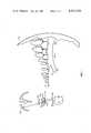
- FIG. 1is a representation of an annular panoramic projection device modified to use the present invention
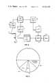
- FIG. 2is a block diagram of the apparatus
- FIG. 3is a representation of a variable resolution mask for use in the apparatus.
- the ultimate goal of a visual flight simulation apparatusis to provide a pilot with a displayed scene which is indistinguishable from the real word in terms of pilot performance on the required task.
- the actual display obtainedmust be a trade-off among the available parameters.
- the visual acuity of the human eyeis one minute of arc inside the fovea of the retina, dropping rapidly outside the fovea to 1/10 of foveal acuity at 20° from the fovea.
- the present inventionis intended to assist a systems designer in advantageously using the drop-off in acuity of the human eye in his design criteria by determining preferred parameters for AOI and IFOV for the system being designed.
- the present inventionallows the designer to determine the acceptable AOI requirements for the particular scene content of the display.
- the detailed display required in the AOIcould be provided by a dedicated CIG channel, while the bulk of the display, being less detailed, could be provided by a second CIG channel.
- FIG. 1illustrates the Surnot application wherein a projection system 10, such as the Surnot, provides a wide angle, 360° in the Surnot, field of view to a subject 11.
- a projection system 10such as the Surnot
- Projection system 10has been modified by placing a servo-driven variable resolution mask 30 near the image plane of system 10.
- a servo-driven variable resolution mask 30In the Surnot system, light from a lamp 101 is reflected by a reflector 102 through a condenser set 103, a transparency 104, and a projector lens 105 before reflecting off a concave mirror 106 and a hyperbolic mirror 107 to a screen 108.
- Mask 30is placed between transparency 104 and lens 105, thereby superimposing its resolution characteristics on the image from transparency 104.
- the resultant image 109then has a resolution profile identified by line 110 in FIG. 1. This corresponds to higher resolution in the AOI 301 and lower resolution in the IFOV 302.
- FIG. 2shows a block diagram of the components of the present invention.
- AOI 301 and IFOV 302must of course follow the line of sight of subject 11 to serve any useful purpose.
- Mask 30is positioned by a servo 40 which receives input signals from an eye tracker 15 and/or a head tracker 16.
- Eye tracker 15could be any of a number of commercially available eye tracking systems, however in the Surnot system a Bimetrics Model 200 has been found to be suitable. This particular model utilizes a pair of silicon photo transistors operating in conjunction with a gallium arsenide IR source and is calibrated for use with an individual subject 11.
- eye tracker 15depends on detecting the changes in reflected light between the white sclera and the left and right side of the iris. With proper calibration, eye tracker 15 can track ⁇ 20° horizontally to an accuracy of 1/4°.
- Head tracker 16may also be any type sensing device which will provide a signal indicative of position with regard to a given reference.
- a simple potentiometercan be used to output head position about a vertical axis.
- Position signals from either head tracker 16 or eye tracker 15can drive servo 40.
- the signal from head tracker 16 and eye tracker 15are then summed in a sum circuit 17 such that they yield a single value for input to servo 40.
- the magnitude of this signaldetermines the displacement of mask 30 to be effected by servo 40.
- Servo 40responds to an input of 55 mv/deg and has the following limitations: position error ⁇ 2°; maximum angular velocity ⁇ 6° /m sec; dynamic jitter ⁇ 5 percent; throughput delay ⁇ 12 m sec; and rotation ⁇ 90°.
- position error ⁇ 2°position error
- maximum angular velocity ⁇ 6° /m secmaximum angular velocity
- dynamic jitter ⁇ 5 percentdynamic ⁇ 5 percent
- throughput delay ⁇ 12 m secthroughput delay ⁇ 12 m sec
- rotation ⁇ 90°servo 40 was built for use in the Surnot trainer and various different servo parameters can be used depending on the requirements of the trainer under study and the task to be simulated.
- Mask 30is one of a plurality of acrylic masks, each providing a variation in the resolution profile presented.
- the masksmay be fabricated according to the needs of the particular simulator design under study. For example, a particular simulator system being developed by the Navy used 21 masks to obtain information on optimum AOI and IFOV relationships.
- the maskshad AOI varying from 15° to 110° and IFOV varying from 40° to 180° in a plurality of combinations.
- the maskmay also provide a peripheral screening area 303, preferably in a gray or black color.
- FIG. 3is a representation of mask 30 wherein AOI 301 is shown bounded by IFOV 302 which is in turn bounded by a peripheral screening area 303.
- projection system 10presents a static or dynamic image 109 on screen 108.
- the resolution across image 109is varied by placing one mask 30 in the optical path of projection system 10.
- a test subject 11is assigned a task similar to the task required in the desired simulator.
- Eye tracker 15 or head tracker 16is attached to subject 11 and servo 40, such that area of intersect 301 is aligned with the line of sight of subject 11.
- the assigned taskis performed and the performance evaluated.
- Mask 30is replaced by a second mask 30 having a different resolution pattern and the task is repeated.
Landscapes
- Engineering & Computer Science (AREA)
- Aviation & Aerospace Engineering (AREA)
- General Engineering & Computer Science (AREA)
- Eye Examination Apparatus (AREA)
Abstract
Description
Claims (11)
Priority Applications (1)
| Application Number | Priority Date | Filing Date | Title |
|---|---|---|---|
| US06/362,829US4421486A (en) | 1982-03-29 | 1982-03-29 | Field of view test apparatus |
Applications Claiming Priority (1)
| Application Number | Priority Date | Filing Date | Title |
|---|---|---|---|
| US06/362,829US4421486A (en) | 1982-03-29 | 1982-03-29 | Field of view test apparatus |
Publications (1)
| Publication Number | Publication Date |
|---|---|
| US4421486Atrue US4421486A (en) | 1983-12-20 |
Family
ID=23427704
Family Applications (1)
| Application Number | Title | Priority Date | Filing Date |
|---|---|---|---|
| US06/362,829Expired - Fee RelatedUS4421486A (en) | 1982-03-29 | 1982-03-29 | Field of view test apparatus |
Country Status (1)
| Country | Link |
|---|---|
| US (1) | US4421486A (en) |
Cited By (16)
| Publication number | Priority date | Publication date | Assignee | Title |
|---|---|---|---|---|
| GB2259213A (en)* | 1991-08-29 | 1993-03-03 | British Aerospace | Variable resolution view-tracking display |
| GB2323231A (en)* | 1989-05-18 | 1998-09-16 | Secr Defence | Imaging systems |
| US5966197A (en)* | 1998-04-21 | 1999-10-12 | Visx, Incorporated | Linear array eye tracker |
| EP1094377A1 (en)* | 1999-10-22 | 2001-04-25 | Bertrand Pittet | Remote control of a vehicle |
| US6283954B1 (en) | 1998-04-21 | 2001-09-04 | Visx, Incorporated | Linear array eye tracker |
| US6299307B1 (en) | 1997-10-10 | 2001-10-09 | Visx, Incorporated | Eye tracking device for laser eye surgery using corneal margin detection |
| US6322216B1 (en) | 1999-10-07 | 2001-11-27 | Visx, Inc | Two camera off-axis eye tracker for laser eye surgery |
| US6327020B1 (en)* | 1998-08-10 | 2001-12-04 | Hiroo Iwata | Full-surround spherical screen projection system and recording apparatus therefor |
| US20030050785A1 (en)* | 2000-01-27 | 2003-03-13 | Siemens Aktiengesellschaft | System and method for eye-tracking controlled speech processing with generation of a visual feedback signal |
| US6644816B1 (en)* | 1998-06-26 | 2003-11-11 | Evolution Technology N.V. | Display device having a cylindrical projection surface such that an image projected onto the inside is visible on the outside |
| US20060139750A1 (en)* | 2000-06-16 | 2006-06-29 | Solomon Dennis J | Performance display system |
| US20100109975A1 (en)* | 2008-10-30 | 2010-05-06 | Honeywell International Inc. | Method and system for operating a near-to-eye display |
| US20130201082A1 (en)* | 2008-06-11 | 2013-08-08 | Honeywell International Inc. | Method and system for operating a near-to-eye display |
| US9265458B2 (en) | 2012-12-04 | 2016-02-23 | Sync-Think, Inc. | Application of smooth pursuit cognitive testing paradigms to clinical drug development |
| US9380976B2 (en) | 2013-03-11 | 2016-07-05 | Sync-Think, Inc. | Optical neuroinformatics |
| US9785231B1 (en)* | 2013-09-26 | 2017-10-10 | Rockwell Collins, Inc. | Head worn display integrity monitor system and methods |
Citations (7)
| Publication number | Priority date | Publication date | Assignee | Title |
|---|---|---|---|---|
| US3888022A (en)* | 1974-06-04 | 1975-06-10 | Us Army | Moving target screen |
| US3998532A (en)* | 1974-04-08 | 1976-12-21 | The United States Of America As Represented By The Secretary Of The Navy | Wide angle single channel projection apparatus |
| US4048653A (en)* | 1974-10-16 | 1977-09-13 | Redifon Limited | Visual display apparatus |
| US4303394A (en)* | 1980-07-10 | 1981-12-01 | The United States Of America As Represented By The Secretary Of The Navy | Computer generated image simulator |
| US4348185A (en)* | 1980-02-14 | 1982-09-07 | The United States Of America As Represented By The Secretary Of The Navy | Wide angle infinity display system |
| US4348186A (en)* | 1979-12-17 | 1982-09-07 | The United States Of America As Represented By The Secretary Of The Navy | Pilot helmet mounted CIG display with eye coupled area of interest |
| US4350489A (en)* | 1980-12-05 | 1982-09-21 | The Singer Company | Dome field of view scene extenders |
- 1982
- 1982-03-29USUS06/362,829patent/US4421486A/ennot_activeExpired - Fee Related
Patent Citations (7)
| Publication number | Priority date | Publication date | Assignee | Title |
|---|---|---|---|---|
| US3998532A (en)* | 1974-04-08 | 1976-12-21 | The United States Of America As Represented By The Secretary Of The Navy | Wide angle single channel projection apparatus |
| US3888022A (en)* | 1974-06-04 | 1975-06-10 | Us Army | Moving target screen |
| US4048653A (en)* | 1974-10-16 | 1977-09-13 | Redifon Limited | Visual display apparatus |
| US4348186A (en)* | 1979-12-17 | 1982-09-07 | The United States Of America As Represented By The Secretary Of The Navy | Pilot helmet mounted CIG display with eye coupled area of interest |
| US4348185A (en)* | 1980-02-14 | 1982-09-07 | The United States Of America As Represented By The Secretary Of The Navy | Wide angle infinity display system |
| US4303394A (en)* | 1980-07-10 | 1981-12-01 | The United States Of America As Represented By The Secretary Of The Navy | Computer generated image simulator |
| US4350489A (en)* | 1980-12-05 | 1982-09-21 | The Singer Company | Dome field of view scene extenders |
Cited By (22)
| Publication number | Priority date | Publication date | Assignee | Title |
|---|---|---|---|---|
| GB2323231A (en)* | 1989-05-18 | 1998-09-16 | Secr Defence | Imaging systems |
| GB2323231B (en)* | 1989-05-18 | 1998-12-23 | Secr Defence | Imaging systems |
| GB2259213A (en)* | 1991-08-29 | 1993-03-03 | British Aerospace | Variable resolution view-tracking display |
| US6299307B1 (en) | 1997-10-10 | 2001-10-09 | Visx, Incorporated | Eye tracking device for laser eye surgery using corneal margin detection |
| US5966197A (en)* | 1998-04-21 | 1999-10-12 | Visx, Incorporated | Linear array eye tracker |
| US6283954B1 (en) | 1998-04-21 | 2001-09-04 | Visx, Incorporated | Linear array eye tracker |
| US6644816B1 (en)* | 1998-06-26 | 2003-11-11 | Evolution Technology N.V. | Display device having a cylindrical projection surface such that an image projected onto the inside is visible on the outside |
| US6327020B1 (en)* | 1998-08-10 | 2001-12-04 | Hiroo Iwata | Full-surround spherical screen projection system and recording apparatus therefor |
| US6322216B1 (en) | 1999-10-07 | 2001-11-27 | Visx, Inc | Two camera off-axis eye tracker for laser eye surgery |
| EP1094377A1 (en)* | 1999-10-22 | 2001-04-25 | Bertrand Pittet | Remote control of a vehicle |
| WO2001031413A1 (en)* | 1999-10-22 | 2001-05-03 | Ldv S.A. | Vehicle remote control |
| US20030050785A1 (en)* | 2000-01-27 | 2003-03-13 | Siemens Aktiengesellschaft | System and method for eye-tracking controlled speech processing with generation of a visual feedback signal |
| US6889192B2 (en)* | 2000-01-27 | 2005-05-03 | Siemens Aktiengesellschaft | Generating visual feedback signals for eye-tracking controlled speech processing |
| US20060139750A1 (en)* | 2000-06-16 | 2006-06-29 | Solomon Dennis J | Performance display system |
| US8194118B2 (en)* | 2000-06-16 | 2012-06-05 | Dennis J Solomon | Performance display system |
| US20130201082A1 (en)* | 2008-06-11 | 2013-08-08 | Honeywell International Inc. | Method and system for operating a near-to-eye display |
| US9594248B2 (en)* | 2008-06-11 | 2017-03-14 | Honeywell International Inc. | Method and system for operating a near-to-eye display |
| US20100109975A1 (en)* | 2008-10-30 | 2010-05-06 | Honeywell International Inc. | Method and system for operating a near-to-eye display |
| US8963804B2 (en) | 2008-10-30 | 2015-02-24 | Honeywell International Inc. | Method and system for operating a near-to-eye display |
| US9265458B2 (en) | 2012-12-04 | 2016-02-23 | Sync-Think, Inc. | Application of smooth pursuit cognitive testing paradigms to clinical drug development |
| US9380976B2 (en) | 2013-03-11 | 2016-07-05 | Sync-Think, Inc. | Optical neuroinformatics |
| US9785231B1 (en)* | 2013-09-26 | 2017-10-10 | Rockwell Collins, Inc. | Head worn display integrity monitor system and methods |
Similar Documents
| Publication | Publication Date | Title |
|---|---|---|
| US4421486A (en) | Field of view test apparatus | |
| US6437759B1 (en) | Vehicle simulator having head-up display | |
| US6943754B2 (en) | Gaze tracking system, eye-tracking assembly and an associated method of calibration | |
| US4634384A (en) | Head and/or eye tracked optically blended display system | |
| EP0032499B1 (en) | Optical illumination and distortion compensator | |
| US4093347A (en) | Optical simulation apparatus using controllable real-life element | |
| US6814578B2 (en) | Visual display system and method for displaying images utilizing a holographic collimator | |
| US4246605A (en) | Optical simulation apparatus | |
| US4205224A (en) | Binocular viewing technique | |
| CA2040272A1 (en) | Variable acuity non-linear projection optics | |
| US20060160049A1 (en) | Flight simulator panel with active graphic display instrumentation | |
| US3557470A (en) | Simulator having visually independent display system | |
| US20070141538A1 (en) | Simulator utilizing a high resolution visual display | |
| CA2587017C (en) | Vision system | |
| CA2496865C (en) | Masked image projection system and method | |
| US4395234A (en) | Optical scanning probe with multiple outputs | |
| US3551043A (en) | Virtual image window display | |
| US4511337A (en) | Simplified hardware component inter-connection system for generating a visual representation of an illuminated area in a flight simulator | |
| US4354737A (en) | Variable gain screen permitting off-axis viewing with image brightness remaining constant | |
| US4111536A (en) | Automatic registration of projector images | |
| CN120217714B (en) | A flight simulation mixed reality display system | |
| Chambers | AWAVS: An engineering simulator for design of visual flight training simulators | |
| CA1254781A (en) | Head and/or eye tracked optically blended display system | |
| Kelly et al. | Helmet-mounted area of interest | |
| Martin et al. | 53.4: Night Vision Goggles: Issues for Simulation and Training |
Legal Events
| Date | Code | Title | Description |
|---|---|---|---|
| AS | Assignment | Owner name:UNITED STATES OF AMERICA AS REPRESENTED BY THE SEC Free format text:ASSIGNMENT OF ASSIGNORS INTEREST.;ASSIGNORS:BALDWIN, DOROTHY M.;OHAREK, FRANK J.;SPOONER, ARCHER M.;REEL/FRAME:003986/0387;SIGNING DATES FROM 19820325 TO 19820326 Owner name:NAVY, THE UNITED STATES OF AMERICA AS REPRESENTED Free format text:ASSIGNMENT OF ASSIGNORS INTEREST;ASSIGNORS:BALDWIN, DOROTHY M.;OHAREK, FRANK J.;SPOONER, ARCHER M.;SIGNING DATES FROM 19820325 TO 19820326;REEL/FRAME:003986/0387 | |
| FEPP | Fee payment procedure | Free format text:MAINTENANCE FEE REMINDER MAILED (ORIGINAL EVENT CODE: REM.); ENTITY STATUS OF PATENT OWNER: LARGE ENTITY | |
| FEPP | Fee payment procedure | Free format text:SURCHARGE FOR LATE PAYMENT, PL 96-517 (ORIGINAL EVENT CODE: M176); ENTITY STATUS OF PATENT OWNER: LARGE ENTITY | |
| MAFP | Maintenance fee payment | Free format text:PAYMENT OF MAINTENANCE FEE, 4TH YEAR, PL 96-517 (ORIGINAL EVENT CODE: M170); ENTITY STATUS OF PATENT OWNER: LARGE ENTITY Year of fee payment:4 | |
| FEPP | Fee payment procedure | Free format text:MAINTENANCE FEE REMINDER MAILED (ORIGINAL EVENT CODE: REM.); ENTITY STATUS OF PATENT OWNER: LARGE ENTITY | |
| LAPS | Lapse for failure to pay maintenance fees | ||
| FP | Lapsed due to failure to pay maintenance fee | Effective date:19911222 | |
| STCH | Information on status: patent discontinuation | Free format text:PATENT EXPIRED DUE TO NONPAYMENT OF MAINTENANCE FEES UNDER 37 CFR 1.362 |