US4421182A - Combination clean-out and drilling tool - Google Patents
Combination clean-out and drilling toolDownload PDFInfo
- Publication number
- US4421182A US4421182AUS06/358,652US35865282AUS4421182AUS 4421182 AUS4421182 AUS 4421182AUS 35865282 AUS35865282 AUS 35865282AUS 4421182 AUS4421182 AUS 4421182A
- Authority
- US
- United States
- Prior art keywords
- assembly
- debris
- tool
- fluid
- bore hole
- Prior art date
- Legal status (The legal status is an assumption and is not a legal conclusion. Google has not performed a legal analysis and makes no representation as to the accuracy of the status listed.)
- Expired - Lifetime
Links
- 238000005553drillingMethods0.000titleclaimsdescription29
- 239000012530fluidSubstances0.000claimsabstractdescription162
- 230000002706hydrostatic effectEffects0.000claimsabstractdescription34
- 238000005520cutting processMethods0.000claimsabstractdescription16
- 230000015572biosynthetic processEffects0.000claimsabstractdescription11
- 238000004891communicationMethods0.000claimsdescription37
- 238000000429assemblyMethods0.000claimsdescription13
- 230000000712assemblyEffects0.000claimsdescription13
- 238000000034methodMethods0.000claimsdescription10
- 238000007789sealingMethods0.000claimsdescription9
- 238000000151depositionMethods0.000claims3
- 230000003213activating effectEffects0.000claims2
- 230000000903blocking effectEffects0.000claims2
- 230000008021depositionEffects0.000claims1
- 238000007599dischargingMethods0.000claims1
- 238000003780insertionMethods0.000claims1
- 230000037431insertionEffects0.000claims1
- 230000003020moisturizing effectEffects0.000claims1
- 238000005755formation reactionMethods0.000description7
- 210000002445nippleAnatomy0.000description7
- 238000005086pumpingMethods0.000description6
- 238000004140cleaningMethods0.000description5
- 238000011084recoveryMethods0.000description4
- 239000002253acidSubstances0.000description3
- 230000009471actionEffects0.000description3
- 230000036461convulsionEffects0.000description3
- 239000003208petroleumSubstances0.000description3
- 239000004215Carbon black (E152)Substances0.000description2
- 230000008901benefitEffects0.000description2
- 229930195733hydrocarbonNatural products0.000description2
- 150000002430hydrocarbonsChemical class0.000description2
- 238000004519manufacturing processMethods0.000description2
- 239000000463materialSubstances0.000description2
- 230000004048modificationEffects0.000description2
- 238000012986modificationMethods0.000description2
- 239000003129oil wellSubstances0.000description2
- 150000003839saltsChemical class0.000description2
- 239000004576sandSubstances0.000description2
- 229910001369BrassInorganic materials0.000description1
- 244000187656Eucalyptus cornutaSpecies0.000description1
- 206010019233HeadachesDiseases0.000description1
- 238000013019agitationMethods0.000description1
- 230000009286beneficial effectEffects0.000description1
- 239000010951brassSubstances0.000description1
- 239000004568cementSubstances0.000description1
- 230000006835compressionEffects0.000description1
- 238000007906compressionMethods0.000description1
- 230000018044dehydrationEffects0.000description1
- 238000006297dehydration reactionMethods0.000description1
- 230000009977dual effectEffects0.000description1
- 239000002360explosiveSubstances0.000description1
- 231100001261hazardousToxicity0.000description1
- 230000006872improvementEffects0.000description1
- 230000007257malfunctionEffects0.000description1
- 230000007246mechanismEffects0.000description1
- 230000036316preloadEffects0.000description1
- 230000008707rearrangementEffects0.000description1
- 239000011435rockSubstances0.000description1
- 239000002002slurrySubstances0.000description1
- 238000006467substitution reactionMethods0.000description1
Images


Classifications
- E—FIXED CONSTRUCTIONS
- E21—EARTH OR ROCK DRILLING; MINING
- E21B—EARTH OR ROCK DRILLING; OBTAINING OIL, GAS, WATER, SOLUBLE OR MELTABLE MATERIALS OR A SLURRY OF MINERALS FROM WELLS
- E21B21/00—Methods or apparatus for flushing boreholes, e.g. by use of exhaust air from motor
- E21B21/10—Valve arrangements in drilling-fluid circulation systems
- E—FIXED CONSTRUCTIONS
- E21—EARTH OR ROCK DRILLING; MINING
- E21B—EARTH OR ROCK DRILLING; OBTAINING OIL, GAS, WATER, SOLUBLE OR MELTABLE MATERIALS OR A SLURRY OF MINERALS FROM WELLS
- E21B27/00—Containers for collecting or depositing substances in boreholes or wells, e.g. bailers, baskets or buckets for collecting mud or sand; Drill bits with means for collecting substances, e.g. valve drill bits
Definitions
- This inventionrelates to oil field production, and in particular to down hole operating devices.
- An oil wellis a hole bored through layers of rock formations to reach a level or bed of petroleum or gas.
- the desired petroleum or gasis often found at a depth as deep as 25,000 feet to 30,000 feet.
- a casingis run into the bore hole and cemented to the sides of the bore hole to keep the bore hole from collapsing.
- a casingis provided along the entire length of the borehole, the casing is perforated at the proper level to permit the top of the petroleum or gas to enter the casing for recovery.
- the casingmay be run into the bore hole down to the hydrocarbon producing formation. This technique is referred to as open hole completion. The portion of the bore hole below the deposit is then unprotected from collapsing.
- a reverse unitmay be employed which includes a rotary device above the oil or gas bore hole to turn a drill pipe or tubing.
- the drill pipe or tubinghas a drill bit on the bottom end thereof and is run down into the bore hole to drill through the debris for cleaning or cleaning by drilling the well deeper.
- the reverse unitincludes a pump on the surface at the bore hole for pumping fluid down hole to recover the debris and pump it to the surface.
- cleaning or drilling circulationis impossible.
- fluidmay not be placed in gas wells as it will push the gas back into the formation and prevent little, if any, recovery of the gas.
- the toolsare placed down hole on a wire line or cable suspended from the surface.
- the wire line toolsbasically operate on two principals, either hydraulic or hydrostatic.
- a hydraulic deviceis disclosed in U.S. Pat. No. 4,190,113 to Harrison issued Feb. 26, 1980. This type of device operates by alternately evacuating and pressurizing a debris chamber with a pumping unit activated by the wire line.
- a one-way valve entering the debris chamber from the bore holepermits debris to flow into the debris container when the container chamber is evacuated. The debris is blocked from flowing out of the borehole by the valve when the chamber is pressurized.
- the pumping assemblyis operated until the debris container chamber is full of debris. The tool is then removed and cleaned for reuse.
- Fluid pumped by the pumping assemblyis discharged horizontally from ports in the device into the narrow annular space between the device and borehole. This inhibits fluid motion downward in this annular space past these ports.
- a tubing stringextends to the surface above the debris chamber.
- a kellypermits rotation of a notched collar below the chamber through the tubing string to break debris crust in the well bore.
- the presence of an empty tubing string in the well boreraises the potential for tubing collapse if the hydrostatic pressure in the well bore acting on the walls of the tubing string becomes to large.
- the hydrostatic toolalso suffers shortcomings.
- the hydrostatic head in the bore hole where the debris is locatedmust be relatively high to permit satisfactory operation of the hydrostatic tool. It is quite expensive to add sufficient fluid to the bore hole to achieve this hydrostatic head if it is not provided naturally. When the well is returned to production, the fluid has to be recovered and disposed of at additional cost. While the hydrostatic tool is effective on large and heavy debris, there is little control of how much the debris containing chamber will contain. Prior known tools provide little control of fluid motion once the debris chamber is exposed to the bore hole pressures and the hydrostatic tool can easily become submerged within the debris and require a fishing operation for removal.
- U.S. Pat. No. 2,992,682 issued July 18, 1961 to Yatesdiscloses a combination tool operable in both the hydrostatic and hydraulic mode. However, this tool is not readily transferrable from one mode of operation to the other and still retains the shortcoming of other known tools in failing to provide an effective technique for removing the tool from the bore hole when buried in debris.
- a tool for use in a bore hole for debris collectionincludes a lower assembly having structure for mounting an accessory at the lower end thereof in the bore hole.
- a debris chamberis provided in the lower assembly for holding debris.
- a one-way valvepositioned in communication with the bore hole and debris chamber permits fluid to flow only from the bore hole into the debris chamber.
- a barrel section in the lower assemblyhas a smooth cylindrical inner wall and is also in fluid communication with the debris chamber through a lower valve assembly.
- Closure structureencloses the upper end of the barrel section in the lower assembly which includes a noncircular aperture therethrough.
- An upper assemblyis provided which has a hollow kelly with a noncircular cross section for sliding motion through the aperture in the closure structure for joint rotation of the upper and lower assemblies.
- a piston assemblyis mounted on the kelley in sliding sealed contact with the inner wall of the barrel section and has at least one port for fluid communication between the debris chamber and hollow kelley, the closure structure and piston assembly being engageable to jerk the lower assembly free from debris.
- the lower part of the piston assemblyfurther acts to open the lower valve assembly to permit flow between the debris chamber and hollow kelly.
- a fluid container in the upper assemblyis provided in fluid communication with the hollow portion of the kelley.
- a drain valveis in fluid communication with the fluid container and the bore hole to relieve fluid pressure from the fluid container.
- An upper valve assemblypermits flow only from the hollow kelley into the fluid container.
- the toolis operable as a hydraulic tool by removing the lower valve assembly and oscillating the upper assembly to reciprocate the piston assembly and drive fluid and debris into the debris chamber during the upstroke.
- At least one discharge valveis provided in fluid communication with the debris chamber.
- the upper valve assembly and discharge valveopen on the downstroke to release the pressure in the debris chamber.
- the toolis operable as a hydrostatic tool by removing the upper valve assembly with the lower valve assembly in place and moving the kelley downward to open the lower valve assembly, driving fluid and debris into the fluid chamber.
- the lower assemblysecures a drill bit at its bottom end in the bore hole. Rotation of the upper and lower assemblies rotates the drill bit and permits drilling operation within the bore hole.
- jet portsare provided proximate the one-way valve between the bore hole and the debris chamber.
- the jet portsact to agitate and moisturize the debris within the tool for improved debris collection.
- Jet portsare also provided in the closure structure in communication with the interior of the barrel section for agitating debris upon upstroke of the piston assembly.
- a method for drilling a bore holeincludes the step of rotating a tool with a drill string or tubing assembly.
- the toolhas upper and lower assemblies with a drill bit being mounted on the lower assembly for contact with the formation to be drilled.
- the methodfurther includes the step of reciprocating the upper assembly relative to the lower assembly.
- the upper assemblyincludes a piston assembly in slideable sealed contact with an inner sealing surface in a section of the lower assembly. The motion of the piston assembly drives fluid and debris from the bore hole into a debris container in the lower assembly to collect the cuttings formed during the drilling.
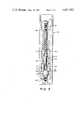
- FIG. 1is a vertical cross sectional view of a tool forming one embodiment of the present invention adapted for use as a hydraulic clean-out or drilling tool;
- FIG. 2is a vertical cross sectional view of the tool adapted for use as a hydrostatic clean-out or drilling tool;
- FIG. 3is a vertical cross sectional view of the lower valve assembly used in the tool in hydrostatic operation.
- FIGS. 1 and 2illustrate a tool 10 forming one embodiment of the present invention.
- the tool 10functions as an improved clean-out tool and is operable in either a hydrostatic or hydraulic mode.
- the tool 10may be operated as a drilling tool to drill a bore hole without need for circulation of drilling fluid from the surface to remove cuttings from the drill face as required in present drilling apparatus.
- FIG. 1illustrates the tool 10 employed as a hydraulic clean-out tool.
- the tool 10comprises two major sections, an upper assembly 12 and a lower assembly 14.
- the upper assembly 12is secured to the last section of a hollow core drill or tubing string assembly 16 which extends to the surface of the bore hole in which the tool is operated.
- the drill or tubing string assemblypreferably comprises hollow tubing of the type employed in drilling operations.
- the upper and lower assembliesare vertically aligned in the bore hole and reciprocal relative to each other as will be described in greater detail hereinafter.
- the upper assemblyincludes a drain valve subassembly 18 which is secured to the lower section of an assembly 16.
- the subassembly 18includes a passageway 20 in fluid communication with the hollow core of the assembly. Drain valves 22 and 24 are provided which act to relieve fluid pressure from within passageway 20 to the bore hole.
- Each drain valveincludes a valve seat 26, a valve ball 28 and a spring 30 to urge the ball into engagement with the valve seat with a predetermined force.
- the tool 10When the tool 10 is lowered into fluid within the bore hole, the tool admits fluid from the bore hole through the passageway 20 and into the hollow tubing forming the assembly 16. This reduces the buoyancy of the tool and assembly 16 to ensure proper operation.
- the drain valves 22 and 24perform this function. Dual drain valves are employed for safety if one malfunctions.
- the drain valvesalso vent excess gas pressure or fluid pressure from the lower sections of the tool 10.
- the springs 30were designed to permit the drain valves 22 and 24 to open at a pressure differential between the passageway and bore hole of greater than 30 psi.
- a fluid container subassembly 32is threaded to the lower end of the drain valve subassembly 18.
- the fluid container assemblyincludes a fluid container 34 therein in fluid communication with passageway 20.
- the fluid containercan comprise any length desired. Typical values of length for the fluid container are 4 feet, 60 feet and 120 feet.
- An upper valve subassembly 36is secured to the lower end of the fluid container subassembly 32.
- Upper valve subassembly 36has a central passage 38 in fluid communication with the fluid container 34.
- the upper valve subassembly 36encloses an upper valve assembly 40 secured to a kelly 86.
- At the lower end of the upper valve subassembly 36is threaded a changeover 42.
- the changeoverpermits a section having tubing threads or tool joint threads such as subassembly 36 to be secured to a section having a spline drive such as kelly 86.
- the changeover 42also mounts a nipple 44 which extends upwardly into the passage 38 and threadably mounts the upper valve assembly 40.
- the upper valve assembly 40includes two separate one-way valves 46 and 48.
- One-way valve 48includes a housing 50 having a ball seat 52 and ball 54.
- a ball stop 56is provided to limit the motion of ball 54.
- One-way valve 46includes a housing 58 defining a ball seat 60.
- a ball 62is moveable into sealing contact with the ball seat 60, limited in its motion by ball stop 64.
- Nipple 44includes a passage 68.
- the passage 68communicates with the port 70 through valve ball seat 60.
- a passage 72interconnects the port 70 with port 74 in ball seat 52.
- a passage 76extends from the one-way valve 48 into a passage 78 in a perforated nipple 80. It is clear that fluid may pass from passage 68 through the one-way valves 46 and 48 through the ports 82 in nipple 80 into the passage 38. However, fluid may not pass from the passage 38 in reverse flow into passage 68.
- the nipple 80prevents debris in the assembly 16 and tool 10 above the upper valve assembly 40 from clogging or plugging the passages through valve assembly 40.
- valve assembly 40installed, reverse circulation of fluid from the surface can be performed to loosen tool 10 from debris if necessary.
- the reverse circulationwould drive fluid down the bore hole from the surface, about the lower portions of tool 10 described hereafter, through valve assembly 40 and returning the fluid to the surface within assembly 16.
- a fishing neck 84is secured at the top of a perforated nipple 80.
- the neck 84is adapted for attachment to a changeover tool inserted within tool 10 to unthread the entire upper valve assembly 40 from nipple 44 and remove assembly 40 while the tool is down hole. This permits conventional circulation downward within assembly 16 to be run within the tool to loosen the tool from debris if desired.
- the kelley 86having a square outer cross section, a hollow center 87 and threaded splines at each end is threaded at its upper end to the changeover 42.
- a changeover safety lock 88is provided to prevent loosening of the spline threads between the kelley and changeover.
- the changeover safety lockincludes a lock flange 90 and two socket head bolts 92 to secure the lock flange to the changeover.
- the lower assembly 14includes a barrel 94 having internal threads at each end.
- An upper barrel nut 96is threaded into the upper threads on barrel 94.
- the upper barrel nut 96has a square aperture 98 for passage of the kelley 86.
- the kelleyextends into the interior of barrel 94 and threadedly receives a seal, guide and swab piston assembly 102 on its lower splines.
- the barrel 94defines a smooth cylindrical honed inner surface 104 along a substantial portion of its interior length.
- the seal guide and swab piston assemblyis designed for sliding sealed contact with the inner surface 104.
- the piston assemblyincludes brass guides 106 for guiding the assembly in its motion.
- Lip seals 108are provided to perform the sealing function.
- the lip sealsare poly-packed.
- the sealsmay be formed of Chevron Uni-pack seals.
- a conical valve opener 110is provided at the lower end of the piston assembly 102.
- the valve openerincludes ports 112 extending both vertically and obliquely to a passage 114 through the interior of the assembly 102.
- the passage 114is in fluid communication with the hollow interior 87 of kelley 86.
- the upper annular surface of assembly 102defines an upper stop 116.
- the upper stopis adapted for engagement with the upper barrel nut 96. Should the lower assembly 14 become buried within debris in the bore hole, the drill string assembly 16 and upper assembly 12 may be jerked upwardly, bringing upper stop 116 into engagement with the nut 96 to jerk the lower assembly 14 free. This feature forms a significant improvement over clean-out tools currently used. The large tensile strength available in the drill or tubing string assembly 16 and tool 10 permits this jerking action to be very effective.
- the piston assembly 102 and barrel 94define an annular chamber 118 and chamber 119 within the interior of the barrel.
- Passageways 120are formed within the upper barrel nut 96 which open at one end into the chamber 118.
- the passagesextend to downwardly directed ports 122 opening into the bore hole. Rapid motion of the piston assembly 102 upwardly drives whatever fluid is in the chamber 118 through the passages 120 and ports 122 at a greatly increased velocity.
- the fluid emanating from the ports 122agitates the debris and other material in the bore hole to render the clean-out operations more effective.
- fluid discharged from ports 122provides down thrust to pull fluid in the bore hole downward past the ports to assist in agitation.
- four jet ports 122are provided.
- a lower valve subassembly 124is threaded to the lower internal threads of barrel 94.
- the interior of lower valve subassembly 124is designed to accept a lower valve assembly 126.
- the lower valve assembly 126is not employed when tool 10 is used in a hydraulic clean-out tool mode. Therefore, the assembly 126 will be discussed in greater detail hereinafter in describing hydrostatic operation.
- a discharge and relief valve subassembly 128is secured to the lower end of the subassembly 124.
- a passage 130is formed through the subassembly 124 which communicates within the lower valve subassembly and chamber 119 in the interior of barrel 94 below the piston assembly 102.
- the subassembly 128mounts discharge and relief valves 132 and 134.
- Each discharge and relief valveincludes a ball seat 136, a ball 138 and a spring 140 to urge the ball into engagement with the seat.
- valves 132 and 134relieve pressure within the passage 130 to the bore hole.
- the discharge and relief valveswill limit the pressure in the fluid in the passage 130. This also relieves the stress on the lip seals on the piston assembly 102 during the downstroke.
- the orifice sizes of the assembly 16 and tool 10 above valves 132 and 134are preferably sized to permit sets of sealer balls to be dropped from the surface, through assembly 16 and tool 10 to block valves 22 and 24 and/or the valves 132 and 134 during circulation through the tool.
- the vertical port 112is sized to permit passage of such sealer balls.
- a debris chamber subassembly 142is secured at the bottom of the discharge valve subassembly.
- the hollow interior of the subassembly 142forms a debris chamber 144.
- the toolwill drive fluid and debris from within the bore hole into the debris chamber where the debris will settle.
- the debris chamberhas been filled, the tool is removed from the bore hole and the chamber is cleaned for reuse.
- the standard length of debris chamberis 50 feet. However, any suitable length may be employed for a particular situation.
- a trap valve subassembly 146is secured at the bottom of the debris chamber subassembly 142.
- the assembly 146mounts a trap valve 148 formed by flapper 150 pivotally secured at one edge to open and close a port 152.
- the portcommunicates between chambers 154 and 156 in the subassembly 146.
- Chamber 154opens into the debris chamber 144 of the debris chamber subassembly 142. Upward motion of the piston assembly 102 creates a vacuum within the lower assembly sufficient to open the flapper valve 150 to drive debris and fluid therethrough from the bore hole.
- a jet port subassembly 158is secured at the bottom of the trap valve subassembly 146 which forms a passage 160 in communication with chamber 156.
- Changeable angled jet ports 162extend upwardly and inwardly from the bore hole into the passage 160.
- fluid from the bore holeis driven through the jet ports 162 to agitate moisture and lift the debris in the passage 160 for more effective debris collection.
- clogging of the toolwas common as a result of dehydration of debris from a slurry, forming hard deposits within the tool, particularly when the debris is sandy.
- a changeover tool 164is secured at the bottom of the jet port subassembly.
- the changeover 164has a hollow center 165 and supports an accessory 166 at its bottom end.
- the accessoryis a drill bit 168.
- the accessoryincludes a hollow core 169 cooperating with the hollow core in changover 164 to drive debris and fluid from the bore hole into passage 160 and eventually into debris chamber 144.
- Other accessoriesmay be provided, such as a wash pipe, junk basket or other device adapted for a particular desired purpose. These accessories can be either devices which previously required circulation within the bore hole or not. As will be described hereafter, tool 10 will provide fluid circulation as necessary through its operation to render the accessories operative.
- the tool 10is run down the bore hole on the drill string assembly 16.
- the upper valve assembly 40is mounted within the upper valve subassembly 36.
- the lower valve assembly 126is removed from the subassembly 124.
- the drill string assembly 16When the tool 10 has contacted the debris pile within the bore hole at drill bit 168, the drill string assembly 16 is reciprocated by a suitable mechanism at the surface.
- the upper assembly 12duplicates the motion.
- the kelley and seal, guide and swab piston assembly 102then reciprocates through aperture 98 and within the interior of barrel 94.
- the discharge and relief valves 132 and 134are employed to relieve pressure below the piston assembly 102.
- fluidmay pass through the ports 112 in passage 114 in the seal, guide and swab piston assembly and through the one-way valves 46 and 48 in the upper valve assembly 40 for discharge through the drain valves 22 and 24.
- the one-way valves 46 and 48close, evacuating the chamber in the interior of the lower assembly below the seal, guide and swab piston assembly 102.
- the vacuumdrives debris and fluid from the bore hole through the internal passage 169 in the drill bit 168, through the flapper valve 150 and into the debris chamber 144 where the debris is deposited.
- the fluid within chamber 118is driven through ports 122 to agitate the debris.
- the fluid passing through jet ports 162further acts to agitate, moisturize and lift the debris in passage 160 to ensure effective collection.
- the drill or tubing string assembly 16may be jerked upwardly. This impacts the upper stop 116 against the upper barrel nut 96 to jerk the tool free. Reverse circulation can also be attempted. If this action is insufficient, a tool may remove the upper valve assembly 40 within the bore hole through attachment at the fishing neck 84.
- the changeover safety lock 88is to prevent loosening of the kelly 86 from changeover 42. Conventional circulation can then be provided from the surface moving down the drill or tubing string assembly 16 and through the tool 10 to free the tool.
- the tool 10When operation as a hydrostatic tool is desired, the tool 10 is configured as illustrated in FIGS. 2 and 3. Many components of tool 10 are used in both hydraulic and hydrostatic operation. One difference in operation as a hydrostatic tool is the removal of the upper valve assembly 40 and the placement of the lower valve assembly 126 within the subassembly 124. The details of the lower valve assembly 126 are best illustrated in FIG. 3.
- the lower valve assembly 126includes a valve body 170 and a valve guide 172 which are confined between the annular surface 174 of the subassembly 124 and the discharge and relief valve subassembly 128.
- a groove 176is provided in the outer wall of the valve body to accept an O-ring 178. The O-ring 178 prevents flow of fluid and debris about the outside of the lower valve assembly.
- the valve body 170includes a seal surface 180 which cooperates with a valve 182 through a seal surface 184 thereon.
- a valve release rod 186extends upwardly from the valve 182 through the center of the valve guide.
- a spring 188acts between a spring retainer nut 190, threaded on an upper threaded portion of the valve release rod and valve guide to urge the sealing surfaces 180 and 184 into sealing engagement in the absence of external influence.
- a retainer nut 192 threaded on a lower threaded portion of rod 186secures the rod 186 to the valve 182. Either or both nuts 190 and 192 are adjusted to vary the compression of spring 188 and preload of surface 184 against surface 180.
- valveWhen the valve is positioned as shown in FIG. 3, no fluid may travel through the passageways 194 between chambers 196 and 198 in the subassembly 124. However, if the rod 186 is moved downwardly through contact with valve opener 110, the sealing surface 184 is disengaged from surface 180 to permit fluid flow between the chambers through the passages 194.
- the passages 200ensure a safe closing of the valve when the valve release rod is permitted to move upwardly by slowing the closing of the valve under the tremendous head pressures often encountered down hole.
- the jet port subassembly 158is positioned between the trap valve subassembly 146 and debris chamber subassembly 142 as illustrated in FIG. 2.
- the tool 10is lowered down hole and suspended from the drill or tubing string assembly 16. Air at atmospheric pressure is confned within the interior of the string assembly 16, upper valve subassembly 36, chamber 119 and chamber 196.
- the jet ports 162admit fluid and valves 132 and 134 discharge air from within the lower assembly to reduce bouyancy to prevent the valve opener 110 from coming into contact with the valve release rod 186 until the lower assembly 14 comes to rest on the debris within the bore hole with the upper assembly 12 movable downward to open the lower valve assembly 126.
- the assembly 16is then moved downwardly to drive the valve opener 110 into the rod 186. This opens the lower valve assembly, permitting fluid and debris to rush into the debris chamber under the tremendous hydrostatic pressures typically found in bore holes where hydrostatic tool clean-out is most beneficial.
- the pressures within the tool and drill string assemblyhave equalized, a large quantity of debris has been entered within the debris chamber and is maintained there by the trap valve 148.
- the toolmay then be lifted to the surface for cleaning. Excess fluid in the assembly 16 and gas pressure is relieved by the drain valves 22 and 24 as the tool 10 moves to the surface. Discharge and relief valves 132 and 134 relieve pressure in the debris chamber 144 and lower assembly. Residual gas and pressure in down hole tools brought to the surface can be very hazardous to both equipment and personnel. Conventional and/or reverse circulation through the tool 10 is possible in the hydrostatic mode by holding lower valve assembly 126 open.
- tool 10used in either hydrostatic or hydraulic operation is the ability to mount accessory 166 at the lower end of the lower assembly 14.
- the drill string assembly 16may be rotated from the surface to rotate the drill bit against the debris.
- the square cross section of the kelley 86 and aperture 98ensures that both lower and upper assemblies 12 and 14 rotate as a unit.
- the tool 10may therefore be used to drill cement retainers or any type of plug or packer.
- the tool 10may be used with accessories using circulation since tool 10 provides fluid circulation in either the hydraulic or hydrostatic modes.
- the accessoryis a drill bit
- tool 10is capable of drilling a new hole or formation without the need for conventional or reverse fluid circulation to remove cuttings as presently used in drilling operations.
- the drillingcan be done by simultaneously reciprocating and rotating the drill string assembly, tool and drill bit.
- the cuttings from the face of the bore holeare driven into the debris chamber on the upstroke of the seal, guide and swab piston assembly entrained in fluid within the bore hole.
- the fluidthen is replaced in the bore hole through one of the drain valves for suspending further cuttings.
- the drilling operationmay then proceed until the debris chamber is completely filled.
- the toolmay be removed to the surface and cleaned for further drilling.
- This techniqueeliminates the necessity of having large fluid pumps at the surface for driving circulating fluid down hole to the cutting face and returning it to the surface where it must be treated and the cuttings removed.
- drillingwould be performed and the cuttings collected in the debris chamber when the lower valve assembly 126 was opened.
- the tool 10would be removed for cleaning and reinserted down hole for further drilling.
Landscapes
- Engineering & Computer Science (AREA)
- Life Sciences & Earth Sciences (AREA)
- Geology (AREA)
- Mining & Mineral Resources (AREA)
- Physics & Mathematics (AREA)
- Environmental & Geological Engineering (AREA)
- Fluid Mechanics (AREA)
- General Life Sciences & Earth Sciences (AREA)
- Geochemistry & Mineralogy (AREA)
- Mechanical Engineering (AREA)
- Earth Drilling (AREA)
Abstract
Description
Claims (21)
Priority Applications (9)
| Application Number | Priority Date | Filing Date | Title |
|---|---|---|---|
| US06/358,652US4421182A (en) | 1982-03-16 | 1982-03-16 | Combination clean-out and drilling tool |
| DE8383901457TDE3378920D1 (en) | 1982-03-16 | 1983-03-14 | Combination clean-out and drilling tool |
| EP83901457AEP0103635B1 (en) | 1982-03-16 | 1983-03-14 | Combination clean-out and drilling tool |
| PCT/US1983/000332WO1983003279A1 (en) | 1982-03-16 | 1983-03-14 | Combination clean-out and drilling tool |
| BR8306483ABR8306483A (en) | 1982-03-16 | 1983-03-14 | TOOL AND PROCESS FOR OPENING DRILLING TO COLLECT DETRITES |
| AU15190/83AAU1519083A (en) | 1982-03-16 | 1983-03-14 | Combination clean-out and drilling tool |
| CA000423696ACA1183517A (en) | 1982-03-16 | 1983-03-16 | Combination clean-out and drilling tool |
| NO83834202ANO162393B (en) | 1982-03-16 | 1983-11-16 | COMBINED CLEANING AND DRILLING TOOL. |
| US06/562,723US4505341A (en) | 1982-03-16 | 1983-12-16 | Combination clean-out and drilling tool |
Applications Claiming Priority (1)
| Application Number | Priority Date | Filing Date | Title |
|---|---|---|---|
| US06/358,652US4421182A (en) | 1982-03-16 | 1982-03-16 | Combination clean-out and drilling tool |
Related Child Applications (1)
| Application Number | Title | Priority Date | Filing Date |
|---|---|---|---|
| US06/562,723Continuation-In-PartUS4505341A (en) | 1982-03-16 | 1983-12-16 | Combination clean-out and drilling tool |
Publications (1)
| Publication Number | Publication Date |
|---|---|
| US4421182Atrue US4421182A (en) | 1983-12-20 |
Family
ID=23410516
Family Applications (1)
| Application Number | Title | Priority Date | Filing Date |
|---|---|---|---|
| US06/358,652Expired - LifetimeUS4421182A (en) | 1982-03-16 | 1982-03-16 | Combination clean-out and drilling tool |
Country Status (5)
| Country | Link |
|---|---|
| US (1) | US4421182A (en) |
| EP (1) | EP0103635B1 (en) |
| CA (1) | CA1183517A (en) |
| DE (1) | DE3378920D1 (en) |
| WO (1) | WO1983003279A1 (en) |
Cited By (37)
| Publication number | Priority date | Publication date | Assignee | Title |
|---|---|---|---|---|
| US4493383A (en)* | 1983-06-07 | 1985-01-15 | Bull Dog Tool Inc. | Well clean out tool |
| US4505341A (en)* | 1982-03-16 | 1985-03-19 | Moody Arlin R | Combination clean-out and drilling tool |
| US4621693A (en)* | 1983-05-03 | 1986-11-11 | The Adaptable Tool Company | Apparatus and methods for pumping solids and undesirable liquids from a well bore |
| US4661052A (en)* | 1984-11-19 | 1987-04-28 | Ruhle James L | Reciprocating down-hole sand pump |
| US4711299A (en)* | 1985-06-26 | 1987-12-08 | The Adaptable Tool Company | Apparatus and methods for pumping solids and undesirable liquids from a well bore |
| US4721156A (en)* | 1987-04-03 | 1988-01-26 | Campbell John F | Well clean out apparatus |
| US4921046A (en)* | 1988-12-13 | 1990-05-01 | Halliburton Company | Horizontal hole cleanup tool |
| US4924940A (en)* | 1987-03-26 | 1990-05-15 | The Cavins Corporation | Downhole cleanout tool |
| US4949788A (en)* | 1989-11-08 | 1990-08-21 | Halliburton Company | Well completions using casing valves |
| US4991653A (en)* | 1989-11-08 | 1991-02-12 | Halliburton Company | Wash tool |
| US5029644A (en)* | 1989-11-08 | 1991-07-09 | Halliburton Company | Jetting tool |
| US5095976A (en)* | 1988-11-08 | 1992-03-17 | Appleton Billy D | Tubing sand pump |
| US5139312A (en)* | 1991-04-09 | 1992-08-18 | Jackson Daryl L | Method and apparatus removing a mineable product from an underground seam |
| US5139095A (en)* | 1991-09-27 | 1992-08-18 | Ingersoll-Rand Company | Method for removing debris from a drillhole |
| US5139089A (en)* | 1991-06-11 | 1992-08-18 | Gcw Development | Well cleanout tool and method |
| US5209293A (en)* | 1992-03-02 | 1993-05-11 | Mobil Oil Corporation | Apparatus for fluidizing formation fines entrained in formation fluids entering a production well penetrating an oil-bearing formation |
| US5325917A (en)* | 1991-10-21 | 1994-07-05 | Halliburton Company | Short stroke casing valve with positioning and jetting tools therefor |
| US5381862A (en)* | 1993-08-27 | 1995-01-17 | Halliburton Company | Coiled tubing operated full opening completion tool system |
| US5531507A (en)* | 1995-05-09 | 1996-07-02 | Jackson; Daryl L. | Method of removing a minable product from an underground seam and bottom hole tool |
| US6719050B2 (en) | 2002-02-06 | 2004-04-13 | Kenneth E. Longacre | Method and apparatus for removing solid material from a well using a rotary pump |
| US20050025645A1 (en)* | 2003-07-30 | 2005-02-03 | Ford Michael Brent | Debris evacuation apparatus and method for an oil pump |
| US20050025644A1 (en)* | 2003-07-30 | 2005-02-03 | Ford Michael Brent | Debris evacuation apparatus and method for an oil pump |
| US20070001134A1 (en)* | 2003-09-15 | 2007-01-04 | Exxonmobil Upstream Research Company | Slurry tolerant pilot operated relief valve |
| WO2009116869A3 (en)* | 2008-02-28 | 2009-11-12 | Innovar Engineering As | Cleaning tool |
| WO2009132274A3 (en)* | 2008-04-24 | 2010-03-04 | Baker Hughes Incorporated | Apparatus and method for discharging multiple fluids downhole |
| US8490702B2 (en) | 2010-02-18 | 2013-07-23 | Ncs Oilfield Services Canada Inc. | Downhole tool assembly with debris relief, and method for using same |
| WO2013089898A3 (en)* | 2011-12-13 | 2014-05-22 | Exxonmobil Upstream Research Company | Completing a well in a reservoir |
| WO2014105056A1 (en)* | 2012-12-28 | 2014-07-03 | Halliburton Energy Services Inc. | Bha surge relief system |
| US8931559B2 (en) | 2012-03-23 | 2015-01-13 | Ncs Oilfield Services Canada, Inc. | Downhole isolation and depressurization tool |
| WO2015191021A1 (en)* | 2014-06-09 | 2015-12-17 | Halliburton Energy Services, Inc. | Fluidic oscillator bypass system |
| US9303486B2 (en) | 2011-11-29 | 2016-04-05 | NCS Multistage, LLC | Tool assembly including an equalization valve |
| US10526871B2 (en) | 2014-04-02 | 2020-01-07 | Odfjell Partners Invest Ltd. | Downhole cleaning apparatus |
| US10648289B2 (en) | 2015-05-27 | 2020-05-12 | Odfjell Partners Invest Ltd | Downhole milling tool |
| US11021933B1 (en) | 2017-09-13 | 2021-06-01 | David A. Webb | Well hole cleaning tool |
| US11655691B2 (en) | 2018-02-12 | 2023-05-23 | Odfjell Technology Invest Ltd | Downhole cleaning apparatus |
| US12060771B2 (en) | 2022-08-08 | 2024-08-13 | Saudi Arabian Oil Company | Downhole clean out tool |
| US12098616B2 (en) | 2020-04-03 | 2024-09-24 | Odfjell Technology Invest Ltd. | Hydraulically locked tool |
Families Citing this family (1)
| Publication number | Priority date | Publication date | Assignee | Title |
|---|---|---|---|---|
| US7352858B2 (en)* | 2004-06-30 | 2008-04-01 | Microsoft Corporation | Multi-channel echo cancellation with round robin regularization |
Citations (12)
| Publication number | Priority date | Publication date | Assignee | Title |
|---|---|---|---|---|
| US1968282A (en)* | 1932-06-04 | 1934-07-31 | Omar A Cavins | Suction fishing tool |
| US2088151A (en)* | 1932-02-15 | 1937-07-27 | Cavins Paul | Bailer or clean-out tool and method |
| US2894585A (en)* | 1954-09-01 | 1959-07-14 | Weldon C Erwin | Hydrostatic washout tool |
| US2992682A (en)* | 1958-10-13 | 1961-07-18 | Claude M Harris | Bailer and sand pump |
| US3255820A (en)* | 1959-11-16 | 1966-06-14 | N A Hardin | Method of treating wells by use of implosive reactions |
| US3406757A (en)* | 1967-07-19 | 1968-10-22 | August B. Baumstimler | Well clean-out tool |
| US3446283A (en)* | 1968-01-02 | 1969-05-27 | August B Baumstimler | Method and apparatus for simultaneously cleaning a well and removing a downhole tool |
| US3651867A (en)* | 1970-10-05 | 1972-03-28 | August B Baumstimler | Combination well clean-out tool and jar |
| US4043150A (en)* | 1976-02-26 | 1977-08-23 | Baumstimler August B | Safety sleeve |
| US4142583A (en)* | 1977-09-02 | 1979-03-06 | Brieger Emmet F | Well tool pack-off with sinker bar release means |
| US4161985A (en)* | 1978-07-07 | 1979-07-24 | The Dow Chemical Company | Tool for removing fluids and loose material from an earth formation |
| US4190113A (en)* | 1978-07-27 | 1980-02-26 | Harrison Wayne O | Well cleanout tool |
Family Cites Families (3)
| Publication number | Priority date | Publication date | Assignee | Title |
|---|---|---|---|---|
| US2192065A (en)* | 1937-09-20 | 1940-02-27 | Harvey D Sandstone | Self-loading and unloading bailer |
| US3286771A (en)* | 1964-02-10 | 1966-11-22 | Automation Oil Corp | Bottom hole oil treater injector |
| US3500933A (en)* | 1968-08-16 | 1970-03-17 | Gulf Oil Corp | Method and apparatus for removing debris from cased wells |
- 1982
- 1982-03-16USUS06/358,652patent/US4421182A/ennot_activeExpired - Lifetime
- 1983
- 1983-03-14DEDE8383901457Tpatent/DE3378920D1/ennot_activeExpired
- 1983-03-14WOPCT/US1983/000332patent/WO1983003279A1/enactiveIP Right Grant
- 1983-03-14EPEP83901457Apatent/EP0103635B1/ennot_activeExpired
- 1983-03-16CACA000423696Apatent/CA1183517A/ennot_activeExpired
Patent Citations (12)
| Publication number | Priority date | Publication date | Assignee | Title |
|---|---|---|---|---|
| US2088151A (en)* | 1932-02-15 | 1937-07-27 | Cavins Paul | Bailer or clean-out tool and method |
| US1968282A (en)* | 1932-06-04 | 1934-07-31 | Omar A Cavins | Suction fishing tool |
| US2894585A (en)* | 1954-09-01 | 1959-07-14 | Weldon C Erwin | Hydrostatic washout tool |
| US2992682A (en)* | 1958-10-13 | 1961-07-18 | Claude M Harris | Bailer and sand pump |
| US3255820A (en)* | 1959-11-16 | 1966-06-14 | N A Hardin | Method of treating wells by use of implosive reactions |
| US3406757A (en)* | 1967-07-19 | 1968-10-22 | August B. Baumstimler | Well clean-out tool |
| US3446283A (en)* | 1968-01-02 | 1969-05-27 | August B Baumstimler | Method and apparatus for simultaneously cleaning a well and removing a downhole tool |
| US3651867A (en)* | 1970-10-05 | 1972-03-28 | August B Baumstimler | Combination well clean-out tool and jar |
| US4043150A (en)* | 1976-02-26 | 1977-08-23 | Baumstimler August B | Safety sleeve |
| US4142583A (en)* | 1977-09-02 | 1979-03-06 | Brieger Emmet F | Well tool pack-off with sinker bar release means |
| US4161985A (en)* | 1978-07-07 | 1979-07-24 | The Dow Chemical Company | Tool for removing fluids and loose material from an earth formation |
| US4190113A (en)* | 1978-07-27 | 1980-02-26 | Harrison Wayne O | Well cleanout tool |
Cited By (49)
| Publication number | Priority date | Publication date | Assignee | Title |
|---|---|---|---|---|
| US4505341A (en)* | 1982-03-16 | 1985-03-19 | Moody Arlin R | Combination clean-out and drilling tool |
| US4621693A (en)* | 1983-05-03 | 1986-11-11 | The Adaptable Tool Company | Apparatus and methods for pumping solids and undesirable liquids from a well bore |
| US4493383A (en)* | 1983-06-07 | 1985-01-15 | Bull Dog Tool Inc. | Well clean out tool |
| US4661052A (en)* | 1984-11-19 | 1987-04-28 | Ruhle James L | Reciprocating down-hole sand pump |
| US4711299A (en)* | 1985-06-26 | 1987-12-08 | The Adaptable Tool Company | Apparatus and methods for pumping solids and undesirable liquids from a well bore |
| US4924940A (en)* | 1987-03-26 | 1990-05-15 | The Cavins Corporation | Downhole cleanout tool |
| US4721156A (en)* | 1987-04-03 | 1988-01-26 | Campbell John F | Well clean out apparatus |
| US5095976A (en)* | 1988-11-08 | 1992-03-17 | Appleton Billy D | Tubing sand pump |
| US4921046A (en)* | 1988-12-13 | 1990-05-01 | Halliburton Company | Horizontal hole cleanup tool |
| US5029644A (en)* | 1989-11-08 | 1991-07-09 | Halliburton Company | Jetting tool |
| US4991653A (en)* | 1989-11-08 | 1991-02-12 | Halliburton Company | Wash tool |
| US4949788A (en)* | 1989-11-08 | 1990-08-21 | Halliburton Company | Well completions using casing valves |
| US5139312A (en)* | 1991-04-09 | 1992-08-18 | Jackson Daryl L | Method and apparatus removing a mineable product from an underground seam |
| US5139089A (en)* | 1991-06-11 | 1992-08-18 | Gcw Development | Well cleanout tool and method |
| US5139095A (en)* | 1991-09-27 | 1992-08-18 | Ingersoll-Rand Company | Method for removing debris from a drillhole |
| US5325917A (en)* | 1991-10-21 | 1994-07-05 | Halliburton Company | Short stroke casing valve with positioning and jetting tools therefor |
| US5209293A (en)* | 1992-03-02 | 1993-05-11 | Mobil Oil Corporation | Apparatus for fluidizing formation fines entrained in formation fluids entering a production well penetrating an oil-bearing formation |
| US5381862A (en)* | 1993-08-27 | 1995-01-17 | Halliburton Company | Coiled tubing operated full opening completion tool system |
| US5531507A (en)* | 1995-05-09 | 1996-07-02 | Jackson; Daryl L. | Method of removing a minable product from an underground seam and bottom hole tool |
| US6719050B2 (en) | 2002-02-06 | 2004-04-13 | Kenneth E. Longacre | Method and apparatus for removing solid material from a well using a rotary pump |
| US7404702B2 (en)* | 2003-07-30 | 2008-07-29 | Michael Brent Ford | Debris evacuation apparatus and method for an oil pump |
| US20050025644A1 (en)* | 2003-07-30 | 2005-02-03 | Ford Michael Brent | Debris evacuation apparatus and method for an oil pump |
| US7008197B2 (en)* | 2003-07-30 | 2006-03-07 | Michael Brent Ford | Debris evacuation apparatus and method for an oil pump |
| US20050025645A1 (en)* | 2003-07-30 | 2005-02-03 | Ford Michael Brent | Debris evacuation apparatus and method for an oil pump |
| US20070001134A1 (en)* | 2003-09-15 | 2007-01-04 | Exxonmobil Upstream Research Company | Slurry tolerant pilot operated relief valve |
| US7467778B2 (en) | 2003-09-15 | 2008-12-23 | Exxonmobil Upstream Research Company | Slurry tolerant pilot operated relief valve |
| WO2009116869A3 (en)* | 2008-02-28 | 2009-11-12 | Innovar Engineering As | Cleaning tool |
| WO2009132274A3 (en)* | 2008-04-24 | 2010-03-04 | Baker Hughes Incorporated | Apparatus and method for discharging multiple fluids downhole |
| US8490702B2 (en) | 2010-02-18 | 2013-07-23 | Ncs Oilfield Services Canada Inc. | Downhole tool assembly with debris relief, and method for using same |
| US9334714B2 (en) | 2010-02-18 | 2016-05-10 | NCS Multistage, LLC | Downhole assembly with debris relief, and method for using same |
| US9303486B2 (en) | 2011-11-29 | 2016-04-05 | NCS Multistage, LLC | Tool assembly including an equalization valve |
| US9587474B2 (en) | 2011-12-13 | 2017-03-07 | Exxonmobil Upstream Research Company | Completing a well in a reservoir |
| WO2013089898A3 (en)* | 2011-12-13 | 2014-05-22 | Exxonmobil Upstream Research Company | Completing a well in a reservoir |
| US9581003B2 (en) | 2011-12-13 | 2017-02-28 | Exxonmobil Upstream Research Company | Completing a well in a reservoir |
| US8931559B2 (en) | 2012-03-23 | 2015-01-13 | Ncs Oilfield Services Canada, Inc. | Downhole isolation and depressurization tool |
| US9140098B2 (en) | 2012-03-23 | 2015-09-22 | NCS Multistage, LLC | Downhole isolation and depressurization tool |
| CN104968884A (en)* | 2012-12-28 | 2015-10-07 | 哈利伯顿能源服务公司 | BHA surge relief system |
| US20150308205A1 (en)* | 2012-12-28 | 2015-10-29 | Halliburton Energy Services Inc. | BHA Surge Relief System |
| WO2014105056A1 (en)* | 2012-12-28 | 2014-07-03 | Halliburton Energy Services Inc. | Bha surge relief system |
| EP2938809A4 (en)* | 2012-12-28 | 2016-09-14 | Halliburton Energy Services Inc | Bha surge relief system |
| AU2012397857B2 (en)* | 2012-12-28 | 2016-12-15 | Halliburton Energy Services Inc. | BHA surge relief system |
| US10526871B2 (en) | 2014-04-02 | 2020-01-07 | Odfjell Partners Invest Ltd. | Downhole cleaning apparatus |
| US11174707B2 (en) | 2014-04-02 | 2021-11-16 | Odfjell Partners Invest Ltd. | Downhole cleaning apparatus |
| WO2015191021A1 (en)* | 2014-06-09 | 2015-12-17 | Halliburton Energy Services, Inc. | Fluidic oscillator bypass system |
| US10648289B2 (en) | 2015-05-27 | 2020-05-12 | Odfjell Partners Invest Ltd | Downhole milling tool |
| US11021933B1 (en) | 2017-09-13 | 2021-06-01 | David A. Webb | Well hole cleaning tool |
| US11655691B2 (en) | 2018-02-12 | 2023-05-23 | Odfjell Technology Invest Ltd | Downhole cleaning apparatus |
| US12098616B2 (en) | 2020-04-03 | 2024-09-24 | Odfjell Technology Invest Ltd. | Hydraulically locked tool |
| US12060771B2 (en) | 2022-08-08 | 2024-08-13 | Saudi Arabian Oil Company | Downhole clean out tool |
Also Published As
| Publication number | Publication date |
|---|---|
| EP0103635B1 (en) | 1989-01-11 |
| EP0103635A1 (en) | 1984-03-28 |
| WO1983003279A1 (en) | 1983-09-29 |
| CA1183517A (en) | 1985-03-05 |
| DE3378920D1 (en) | 1989-02-16 |
| EP0103635A4 (en) | 1985-09-16 |
Similar Documents
| Publication | Publication Date | Title |
|---|---|---|
| US4421182A (en) | Combination clean-out and drilling tool | |
| US4505341A (en) | Combination clean-out and drilling tool | |
| US4190113A (en) | Well cleanout tool | |
| US4924940A (en) | Downhole cleanout tool | |
| US4711299A (en) | Apparatus and methods for pumping solids and undesirable liquids from a well bore | |
| US4493383A (en) | Well clean out tool | |
| US5890538A (en) | Reverse circulation float equipment tool and process | |
| CA2618409C (en) | Casing bottom hole assembly retrieval process | |
| US6089322A (en) | Method and apparatus for increasing fluid recovery from a subterranean formation | |
| EP2501893B1 (en) | Tubular retrieval | |
| US5119874A (en) | Swab cup and swab assembly | |
| US2227729A (en) | Packer and sampling assembly | |
| US4478285A (en) | Method and apparatus for removal of downhole well debris | |
| US5139089A (en) | Well cleanout tool and method | |
| US4621693A (en) | Apparatus and methods for pumping solids and undesirable liquids from a well bore | |
| US3651867A (en) | Combination well clean-out tool and jar | |
| WO1991017339A1 (en) | Method and apparatus for drilling and coring | |
| CN1311141C (en) | Method for drilling a borehole and wet boring tool | |
| RU2099506C1 (en) | Device for well depression cleanup | |
| US20020157871A1 (en) | Apparatus and method of oscillating a drill string | |
| US2652000A (en) | Combination reservoir energy and pumping equipment control | |
| RU2123577C1 (en) | Device for cleaning well-adjoining zone in productive oil beds | |
| CA3006884C (en) | Modified downhole isolation tool having a seating means and ported sliding sleeve | |
| RU2119042C1 (en) | Device for cleaning bottom-hole of well from sediment accumulations | |
| JPH0361836B2 (en) |
Legal Events
| Date | Code | Title | Description |
|---|---|---|---|
| STCF | Information on status: patent grant | Free format text:PATENTED CASE | |
| CC | Certificate of correction | ||
| AS | Assignment | Owner name:MCDONALD, GEORGE PAT, P.O. DRAWER 880, CASTROVILLE Free format text:ASSIGNMENT OF ASSIGNORS INTEREST.;ASSIGNOR:MOODY, ARLIN R;REEL/FRAME:004373/0517 Effective date:19850208 Owner name:MCDONALD, GEORGE PAT, P.O. DRAWER 880, CASTROVILLE Free format text:ASSIGNMENT OF ASSIGNORS INTEREST.;ASSIGNOR:MOODY, BOBBY J.;REEL/FRAME:004373/0518 Effective date:19850208 | |
| MAFP | Maintenance fee payment | Free format text:PAYMENT OF MAINTENANCE FEE, 4TH YEAR, PL 96-517 (ORIGINAL EVENT CODE: M170); ENTITY STATUS OF PATENT OWNER: SMALL ENTITY Year of fee payment:4 | |
| AS | Assignment | Owner name:HY-TECH TOOL INTERNATIONAL, LTD., 9434 OLD KATY RO Free format text:ASSIGNMENT OF ASSIGNORS INTEREST.;ASSIGNOR:HY-TECH TOOL, INC.,;REEL/FRAME:004885/0772 Effective date:19880502 Owner name:HY-TECH TOOL INTERNATIONAL, LTD.,TEXAS Free format text:ASSIGNMENT OF ASSIGNORS INTEREST;ASSIGNOR:HY-TECH TOOL, INC.,;REEL/FRAME:004885/0772 Effective date:19880502 | |
| AS | Assignment | Owner name:HY-TECH TOOL INTERNATIONAL, LTD., TEXAS Free format text:ASSIGNMENT OF ASSIGNORS INTEREST.;ASSIGNOR:HY-TECH TOO, INC.,;REEL/FRAME:005132/0756 Effective date:19890809 | |
| MAFP | Maintenance fee payment | Free format text:PAYMENT OF MAINTENANCE FEE, 8TH YEAR, PL 96-517 (ORIGINAL EVENT CODE: M171); ENTITY STATUS OF PATENT OWNER: SMALL ENTITY Year of fee payment:8 | |
| AS | Assignment | Owner name:HYTECH TOOL, INC., TEXAS Free format text:ASSIGNMENT OF ASSIGNORS INTEREST.;ASSIGNOR:MCDONALD, GEORGE PAT;REEL/FRAME:005816/0282 Effective date:19850510 | |
| AS | Assignment | Owner name:EXCELSIOR LEASING COMPANY A CORP. OF TEXAS, TEXAS Free format text:ASSIGNMENT OF ASSIGNORS INTEREST.;ASSIGNOR:HY-TECH TOOL INTERNATIONAL, LTD.;REEL/FRAME:005869/0398 Effective date:19910923 | |
| FEPP | Fee payment procedure | Free format text:MAINTENANCE FEE REMINDER MAILED (ORIGINAL EVENT CODE: REM.); ENTITY STATUS OF PATENT OWNER: SMALL ENTITY | |
| FEPP | Fee payment procedure | Free format text:SURCHARGE FOR LATE PAYMENT, SMALL ENTITY (ORIGINAL EVENT CODE: M286); ENTITY STATUS OF PATENT OWNER: SMALL ENTITY | |
| MAFP | Maintenance fee payment | Free format text:PAYMENT OF MAINTENANCE FEE, 12TH YR, SMALL ENTITY (ORIGINAL EVENT CODE: M285); ENTITY STATUS OF PATENT OWNER: SMALL ENTITY Year of fee payment:12 | |
| FP | Lapsed due to failure to pay maintenance fee | Effective date:19951220 |